SINAMICS G120 with CU240S DP (FW3.2) - Teknika Otomasyon
SINAMICS G120 with CU240S DP (FW3.2) - Teknika Otomasyon
SINAMICS G120 with CU240S DP (FW3.2) - Teknika Otomasyon

Create successful ePaper yourself
Turn your PDF publications into a flip-book with our unique Google optimized e-Paper software.
Cover<br />
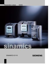
<strong>SINAMICS</strong> <strong>G120</strong><br />
<strong>with</strong> <strong>CU240S</strong> <strong>DP</strong> (<strong>FW3.2</strong>)<br />
Control via PROFIBUS<br />
Application • July 2010<br />
Applikationen & Tools<br />
Answers for industry.
Industry Automation and Drives Technologies Service & Support Portal<br />
This article is taken from the Service Portal of Siemens AG, Industry Automation<br />
and Drives Technologies. The following link takes you directly to the download<br />
page of this document.<br />
http://support.automation.siemens.com/WW/view/en/45288241<br />
If you have any questions concerning this document please e-mail us to the<br />
following address:<br />
online-support.automation@siemens.com<br />
Copyright © Siemens AG 2010 All rights reserved<br />
2<br />
<strong>SINAMICS</strong> <strong>G120</strong> (<strong>CU240S</strong> <strong>DP</strong>) Control via PROFIBUS<br />
V1.0, Beitrags-ID: 45288241
Warranty and Liability<br />
Note<br />
Warranty and Liability<br />
The Application Examples are not binding and do not claim to be complete<br />
regarding the circuits shown, equipping and any eventuality. The Application<br />
Examples do not represent customer-specific solutions. They are only intended<br />
to provide support for typical applications. You are responsible for ensuring that<br />
the described products are used correctly. These application examples do not<br />
relieve you of the responsibility to use safe practices in application, installation,<br />
operation and maintenance. When using these Application Examples, you<br />
recognize that we cannot be made liable for any damage/claims beyond the<br />
liability clause described. We reserve the right to make changes to these<br />
Application Examples at any time <strong>with</strong>out prior notice.<br />
If there are any deviations between the recommendations provided in these<br />
application examples and other Siemens publications – e.g. Catalogs – the<br />
contents of the other documents have priority.<br />
We do not accept any liability for the information contained in this document.<br />
Copyright © Siemens AG 2010 All rights reserved<br />
<strong>G120</strong>_STD_APP1_en.doc<br />
Any claims against us – based on whatever legal reason – resulting from the use of<br />
the examples, information, programs, engineering and performance data etc.,<br />
described in this Application Example shall be excluded. Such an exclusion shall<br />
not apply in the case of mandatory liability, e.g. under the German Product Liability<br />
Act (“Produkthaftungsgesetz”), in case of intent, gross negligence, or injury of life,<br />
body or health, guarantee for the quality of a product, fraudulent concealment of a<br />
deficiency or breach of a condition which goes to the root of the contract<br />
(“wesentliche Vertragspflichten”). The damages for a breach of a substantial<br />
contractual obligation are, however, limited to the foreseeable damage, typical for<br />
the type of contract, except in the event of intent or gross negligence or injury to<br />
life, body or health. The above provisions do not imply a change of the burden of<br />
proof to your detriment.<br />
Any form of duplication or distribution of these Application Examples or excerpts<br />
hereof is prohibited <strong>with</strong>out the expressed consent of Siemens Industry Sector.<br />
<strong>SINAMICS</strong> <strong>G120</strong> (<strong>CU240S</strong> <strong>DP</strong>) Control via PROFIBUS<br />
V1.0, Beitrags-ID: 45288241 3
Table of Contents<br />
Copyright © Siemens AG 2010 All rights reserved<br />
Table of Contents<br />
Warranty and Liability ................................................................................................. 3<br />
1 Automation function.......................................................................................... 5<br />
1.1 Description of the functionality ............................................................. 5<br />
2 Functionality of the function example............................................................. 6<br />
2.1.1 Task description ................................................................................... 6<br />
2.1.2 Solution ................................................................................................ 6<br />
2.2 Structure of the function example ........................................................ 6<br />
3 Components that are required ......................................................................... 7<br />
3.1 Hardware components ......................................................................... 7<br />
3.2 Software components........................................................................... 7<br />
4 Configuration and wiring .................................................................................. 8<br />
4.1 Overview of the hardware configuration............................................... 8<br />
4.2 Connecting-up the hardware components ........................................... 9<br />
4.2.1 S7-300 control and <strong>CU240S</strong> <strong>DP</strong>-F....................................................... 9<br />
4.2.2 PM240 and motor............................................................................... 10<br />
4.3 Fault 395 (acceptance test / acknowledgement present) .................. 11<br />
4.4 Important hardware component settings............................................ 11<br />
4.4.1 SM374 simulation module.................................................................. 11<br />
4.4.2 <strong>SINAMICS</strong> <strong>G120</strong> ................................................................................ 12<br />
4.5 Overview of inputs and outputs.......................................................... 13<br />
4.5.1 Simulation module SM374 ................................................................. 13<br />
4.5.2 <strong>SINAMICS</strong> <strong>G120</strong> ................................................................................ 14<br />
5 Download.......................................................................................................... 15<br />
5.1 S7 program......................................................................................... 15<br />
5.2 <strong>SINAMICS</strong> <strong>G120</strong> configuration .......................................................... 16<br />
5.3 Exiting the STARTER parameterizing software ................................. 17<br />
6 Key performance data of the SIMATIC CPU.................................................. 18<br />
7 Background information................................................................................. 19<br />
7.1 Settings in the hardware configuration............................................... 19<br />
7.1.1 Properties of the <strong>SINAMICS</strong> <strong>G120</strong>..................................................... 20<br />
7.2 Functions of the Step 7 program........................................................ 23<br />
7.2.1 Program overview .............................................................................. 23<br />
7.2.2 DB1, Axis_DB..................................................................................... 24<br />
7.2.3 FB10, Organization ............................................................................ 25<br />
7.2.4 FC100, Control of <strong>SINAMICS</strong> <strong>G120</strong>................................................... 25<br />
7.3 <strong>SINAMICS</strong> <strong>G120</strong> parameterization .................................................... 26<br />
7.3.1 SIMATIC Manager - inserting <strong>SINAMICS</strong> <strong>G120</strong> , .............................. 26<br />
7.3.2 Calling the STARTER parameterization tool...................................... 27<br />
7.3.3 STARTER - carrying out quick commissioning .................................. 27<br />
7.3.4 STARTER - carrying out a motor identification routine...................... 28<br />
7.3.5 STARTER - setting the Profibus communications ............................. 29<br />
8 Appendix .......................................................................................................... 31<br />
8.1 Internet link data................................................................................. 31<br />
8.2 History ................................................................................................ 31<br />
4<br />
<strong>SINAMICS</strong> <strong>G120</strong> (<strong>CU240S</strong> <strong>DP</strong>) Control via PROFIBUS<br />
V1.0, Beitrags-ID: 45288241
1 Automation function<br />
1 Automation function<br />
1.1 Description of the functionality<br />
The <strong>SINAMICS</strong> <strong>G120</strong> drive inverter is a modular inverter system <strong>with</strong> degree of<br />
protection IP20. It comprises the two function units Control Unit (CU) and Power<br />
Module (PM).<br />
When using the Control Unit <strong>CU240S</strong> <strong>DP</strong>, you have the possibility to use the<br />
profibus <strong>DP</strong> interface. This interface can be used for data exchange between<br />
inverter and control and to run the drive <strong>with</strong> the control.<br />
Copyright © Siemens AG 2010 All rights reserved<br />
<strong>SINAMICS</strong> <strong>G120</strong> (<strong>CU240S</strong> <strong>DP</strong>) Control via PROFIBUS<br />
V1.0, Beitrags-ID: 45288241 5
2 Functionality of the function example<br />
2 Functionality of the function example<br />
2.1.1 Task description<br />
The <strong>SINAMICS</strong> <strong>G120</strong> is to be controlled from an S7-300 CPU via Profibus.<br />
2.1.2 Solution<br />
In this function example, the control of a <strong>SINAMICS</strong> <strong>G120</strong> (control word and<br />
frequency setpoint) will be demonstrated using an S7-300 CPU and a specific<br />
program example.<br />
This program example comprises an S7 program to control the <strong>SINAMICS</strong> <strong>G120</strong><br />
and the appropriate configuration in the <strong>SINAMICS</strong> <strong>G120</strong>.<br />
2.2 Structure of the function example<br />
Copyright © Siemens AG 2010 All rights reserved<br />
• In Chapter 3 the required hard and software components for the functionexamples<br />
are shown.<br />
• The download and test of the program examples supplied are described in<br />
Chapters 4 to 5.<br />
• Chapter 6 informs about the key performance date.<br />
• In Chapter 7 more detailed information are delivered. These Steps are not<br />
necessary for the commissioning of the function-example and you don’t have<br />
to do these because they are already included in the S7-Program and<br />
accordingly the <strong>SINAMICS</strong> <strong>G120</strong> Project. The given information should help<br />
you <strong>with</strong> the creation of your own projects.<br />
6<br />
<strong>SINAMICS</strong> <strong>G120</strong> (<strong>CU240S</strong> <strong>DP</strong>) Control via PROFIBUS<br />
V1.0, Beitrags-ID: 45288241
3 Components that are required<br />
3 Components that are required<br />
An overview of the hardware and software components required for the function<br />
example is provided in the Chapter.<br />
3.1 Hardware components<br />
Component Type Order No./ordering data Qty Manufacturer<br />
S7 control<br />
Power supply PS307 5A 6ES7307-1EA00-0AA0 1<br />
S7-CPU CPU 315-2 PN / <strong>DP</strong> 6ES7315-2EH13-0AB0 1<br />
Memory Card MMC 512 KB 6ES7953-8LJ11-0AA0 1<br />
DI / DO simulation module SM374 6ES7374-2XH01-0AA0 1<br />
Profile rail Profile rail 6ES7390-1AE80-0AA0 1<br />
Profibus connector Profibus connector 6ES7972-0BB50-0XA0 2<br />
Profibus cable Profibus cable 6XV1830-3BH10 2 m<br />
Drive<br />
<strong>SINAMICS</strong> <strong>G120</strong> Control Unit * <strong>CU240S</strong> <strong>DP</strong> F 6SL3244-0BA21-1PA0 1<br />
<strong>SINAMICS</strong> <strong>G120</strong> Power Module * PM240 6SL3224-0BE21-5UA0 1<br />
Basic Operator Panel * BOP 6SL3255-0AA00-4BA1 1<br />
Motor *<br />
Three-phase induction<br />
motor<br />
1LA7060-4AB10 1<br />
SIEMENS<br />
SIEMENS<br />
Copyright © Siemens AG 2010 All rights reserved<br />
Note<br />
As an alternative to the components marked <strong>with</strong> *, the <strong>SINAMICS</strong> <strong>G120</strong> training<br />
case can also be used that is additionally equipped <strong>with</strong> a 24V HTL encoder and a<br />
mechanical brake. This training case can be ordered by specifying Order No.<br />
6ZB2480-0CD00.<br />
The functionality was tested <strong>with</strong> the specified hardware components.<br />
Similar components that are different from those listed above can be used.<br />
Please note that in such a case it may be necessary to change the code<br />
example (e.g. setting other addresses).<br />
3.2 Software components<br />
Component Version Order No. / ordering data Qty Manufacturer<br />
V5.4 + SP5 +<br />
SIMATIC STEP 7<br />
6ES7810-4CC08-0YA5 1<br />
HF1<br />
V4.1 + SP5 + http://support.automation.siemens.com/<br />
STARTER 1<br />
HF1<br />
WW/view/en/26233208<br />
http://support.automation.siemens.com/<br />
GSD-File <strong>CU240S</strong> <strong>DP</strong> V3.2 1<br />
WW/view/en/23450835<br />
SIEMENS<br />
<strong>SINAMICS</strong> <strong>G120</strong> (<strong>CU240S</strong> <strong>DP</strong>) Control via PROFIBUS<br />
V1.0, Beitrags-ID: 45288241 7
4 Configuration and wiring<br />
4 Configuration and wiring<br />
!<br />
Warning<br />
The hardware configuration and connecting-up the function example are described<br />
in this Chapter.<br />
Please carefully observe the following safety information & instructions when using<br />
the <strong>SINAMICS</strong> <strong>G120</strong>:<br />
The <strong>SINAMICS</strong> <strong>G120</strong> has hazardous voltages and controls rotating mechanical<br />
parts that can also be potentially hazardous. If the warning information is not<br />
observed or the information & instructions from the instructions belonging to<br />
<strong>SINAMICS</strong> <strong>G120</strong> are not complied <strong>with</strong> this could result in death, severe bodily<br />
injury or significant material damage.<br />
4.1 Overview of the hardware configuration<br />
Copyright © Siemens AG 2010 All rights reserved<br />
8<br />
<strong>SINAMICS</strong> <strong>G120</strong> (<strong>CU240S</strong> <strong>DP</strong>) Control via PROFIBUS<br />
V1.0, Beitrags-ID: 45288241
Copyright © Siemens AG 2010 All rights reserved<br />
4 Configuration and wiring<br />
4.2 Connecting-up the hardware components<br />
4.2.1 S7-300 control and <strong>CU240S</strong> <strong>DP</strong>-F<br />
<strong>SINAMICS</strong> <strong>G120</strong> (<strong>CU240S</strong> <strong>DP</strong>) Control via PROFIBUS<br />
V1.0, Beitrags-ID: 45288241 9
4 Configuration and wiring<br />
4.2.2 PM240 and motor<br />
L1<br />
L2<br />
L3<br />
PE<br />
<strong>SINAMICS</strong> <strong>G120</strong><br />
PM240<br />
Copyright © Siemens AG 2010 All rights reserved<br />
PE<br />
L<br />
U1<br />
L1<br />
N<br />
V1<br />
L2<br />
W1<br />
L3<br />
U2 V2 W2 PE<br />
For more detailed information regarding the installation please refer to the <strong>SINAMICS</strong> <strong>G120</strong> Hardware Installation Manual Power<br />
Module PM240. Download from: http://support.automation.siemens.com/WW/view/en/22339653/133300<br />
10<br />
<strong>SINAMICS</strong> <strong>G120</strong> (<strong>CU240S</strong> <strong>DP</strong>) Control via PROFIBUS<br />
V1.0, Beitrags-ID: 45288241
4 Configuration and wiring<br />
4.3 Fault 395 (acceptance test / acknowledgement present)<br />
Fault F395 is output when powering-up for the first time and after replacing the<br />
Control Unit (CU) or the Power Module (PM).<br />
This fault does not represent an incorrect drive inverter function. The reason for<br />
this fault message is to monitor the individual drive inverter components (CU and<br />
PM) to prevent them from being replaced by unauthorized personnel.<br />
Acknowledging fault F395<br />
Just like any other fault, it can be acknowledged using an appropriately<br />
parameterized input, via the field bus or using the STARTER parameterizing<br />
software.<br />
4.4 Important hardware component settings<br />
Most of the module/board settings are made in the HW Config in the software.<br />
Hardware settings are only required for the following modules/boards.<br />
The modules/boards must be set <strong>with</strong> the control system in a no-voltage state.<br />
4.4.1 SM374 simulation module<br />
Copyright © Siemens AG 2010 All rights reserved<br />
This module can be operated as 16 x DO (output via LED), 16 x DI (input via<br />
switch) or as combined 8 x DI / 8 x DO. The last combination is used in this<br />
function description.<br />
The function of the module is selected using a rotary switch behind the front cover<br />
between the series of switches.<br />
As shown in the following diagram set the function switches to the setting 8 x<br />
Output 8 x Input.<br />
<strong>SINAMICS</strong> <strong>G120</strong> (<strong>CU240S</strong> <strong>DP</strong>) Control via PROFIBUS<br />
V1.0, Beitrags-ID: 45288241 11
4 Configuration and wiring<br />
4.4.2 <strong>SINAMICS</strong> <strong>G120</strong><br />
The Profibus address must be set on the right-hand side of the Control Unit<br />
according to HW Config.<br />
Using the DIL switch, set address 10 as shown in the following diagram.<br />
Copyright © Siemens AG 2010 All rights reserved<br />
12<br />
<strong>SINAMICS</strong> <strong>G120</strong> (<strong>CU240S</strong> <strong>DP</strong>) Control via PROFIBUS<br />
V1.0, Beitrags-ID: 45288241
4 Configuration and wiring<br />
4.5 Overview of inputs and outputs<br />
4.5.1 Simulation module SM374<br />
Copyright © Siemens AG 2010 All rights reserved<br />
Address Function Symbolic address Default Explanation<br />
O 0.0<br />
Indicator lamp<br />
error<br />
<strong>SINAMICS</strong><br />
I 0.0 Start_<strong>G120</strong> 0<br />
<strong>G120</strong> start<br />
<strong>SINAMICS</strong><br />
I 0.1 Reverse_<strong>G120</strong> 0<br />
<strong>G120</strong> reverse<br />
error 0 faults are signaled via this output<br />
The motor connected to <strong>SINAMICS</strong> <strong>G120</strong> is started by<br />
activating the input<br />
After the input is activated, a negative frequency<br />
setpoint is entered (direction of rotation reversal)<br />
Increase<br />
I 0.5 Increase_frequency 0 The motor frequency can be increased using this input<br />
frequency<br />
Decrease<br />
I 0.6 Decrease_frequency 0 The motor frequency can be reduced using this input<br />
frequency<br />
Acknowledge<br />
I 0.7 ACK_error 0<br />
error<br />
Fault messages that are present can be acknowledged<br />
using this input.<br />
<strong>SINAMICS</strong> <strong>G120</strong> (<strong>CU240S</strong> <strong>DP</strong>) Control via PROFIBUS<br />
V1.0, Beitrags-ID: 45288241 13
4 Configuration and wiring<br />
4.5.2 <strong>SINAMICS</strong> <strong>G120</strong><br />
The <strong>SINAMICS</strong> <strong>G120</strong> is controlled and the feedback signals read-in via the I/O<br />
addresses listed below.<br />
Address<br />
Function<br />
S7 program -> <strong>SINAMICS</strong> <strong>G120</strong><br />
Copyright © Siemens AG 2010 All rights reserved<br />
PQW256 Control word 1<br />
PQW258<br />
PQW260<br />
Frequency setpoint<br />
Torque setpoint<br />
PQW262 Control word 2<br />
PQW264 -- Reserve --<br />
PQW266 -- Reserve --<br />
PIW256 Status word 1<br />
PIW258<br />
PIW260<br />
Frequency actual value<br />
Current actual value<br />
PIW262 Status word 2<br />
PIW264<br />
PIW266<br />
Last fault number<br />
Last alarm number<br />
<strong>SINAMICS</strong> <strong>G120</strong> -> S7 program<br />
For more detailed information about the configuration of the individual signals,<br />
please refer to <strong>SINAMICS</strong> <strong>G120</strong> Operating Instructions Control Unit <strong>CU240S</strong>,<br />
Chapter Commissioning.<br />
Download from:<br />
http://support.automation.siemens.com/WW/view/en/22339653/133300<br />
14<br />
<strong>SINAMICS</strong> <strong>G120</strong> (<strong>CU240S</strong> <strong>DP</strong>) Control via PROFIBUS<br />
V1.0, Beitrags-ID: 45288241
5 Download<br />
5 Download<br />
5.1 S7 program<br />
To download the S7 program, you will require a connection between the MPI<br />
interface of your PG/PC and the MPI interface of the S7 CPU.<br />
• Start the SIMATIC Manager.<br />
• De-archive the function example supplied.<br />
• Open the <strong>G120</strong>_STD_APP1 project.<br />
• Select the PROFIBUS interface parameterization using Options > Select<br />
PG/PC interface… .<br />
• Open HW-Config and download this into the control. After the download reclose<br />
HW-Config.<br />
• In SIMATIC Manager, select the block folder via CPU315-2 PN/<strong>DP</strong> > S7<br />
Program > Blocks.<br />
• Download all of the S7 program blocks into the CPU<br />
Copyright © Siemens AG 2010 All rights reserved<br />
<strong>SINAMICS</strong> <strong>G120</strong> (<strong>CU240S</strong> <strong>DP</strong>) Control via PROFIBUS<br />
V1.0, Beitrags-ID: 45288241 15
5 Download<br />
5.2 <strong>SINAMICS</strong> <strong>G120</strong> configuration<br />
When this has been completed, download the <strong>SINAMICS</strong> <strong>G120</strong> configuration using<br />
the STARTER parameterizing tool.<br />
• Starting from the main path of the SIMATIC Manager, start the STARTER<br />
parameterizing software by selecting the <strong>SINAMICS</strong>_<strong>G120</strong> icon and double<br />
click on the Inbetriebnahme icon.<br />
• Then, in the Project Navigator of the STARTER parameterizing software select<br />
the object "<strong>G120</strong>" (1.) and press the button (2.) to establish the online<br />
connection to the drive inverter.<br />
Copyright © Siemens AG 2010 All rights reserved<br />
• After you have established the online connection, press the button to<br />
download the <strong>SINAMICS</strong> <strong>G120</strong> drive parameters.<br />
• Follow the instructions on the screen and acknowledge the prompt "After<br />
loading, copy RAM to ROM".<br />
16<br />
<strong>SINAMICS</strong> <strong>G120</strong> (<strong>CU240S</strong> <strong>DP</strong>) Control via PROFIBUS<br />
V1.0, Beitrags-ID: 45288241
5 Download<br />
5.3 Exiting the STARTER parameterizing software<br />
• If you don't wish to set any additional parameters, then you can now exit the<br />
STARTER commissioning tool.<br />
• In the tree select <strong>SINAMICS</strong> <strong>G120</strong> and transfer all of the parameter changes<br />
into the ROM memory of the <strong>SINAMICS</strong> <strong>G120</strong> by pressing the button<br />
• Then transfer all of the parameters into your offline a project by pressing the<br />
button.<br />
• Disconnect the PG / PC from <strong>SINAMICS</strong> <strong>G120</strong> by pressing the<br />
button.<br />
• Now you can close STARTER using Project > Close or by pressing the<br />
button.<br />
Copyright © Siemens AG 2010 All rights reserved<br />
<strong>SINAMICS</strong> <strong>G120</strong> (<strong>CU240S</strong> <strong>DP</strong>) Control via PROFIBUS<br />
V1.0, Beitrags-ID: 45288241 17
6 Key performance data of the SIMATIC CPU<br />
6 Key performance data of the SIMATIC CPU<br />
Load memory and working memory<br />
Total<br />
Load memory<br />
Working memory<br />
Approx. 6 k<br />
Approx. 2 k<br />
Cycle time<br />
Total cycle time (typical)<br />
Approx. 1ms<br />
Copyright © Siemens AG 2010 All rights reserved<br />
18<br />
<strong>SINAMICS</strong> <strong>G120</strong> (<strong>CU240S</strong> <strong>DP</strong>) Control via PROFIBUS<br />
V1.0, Beitrags-ID: 45288241
7 Background information<br />
7 Background information<br />
The individual functions of the example code are explained in the following<br />
Chapters so that you will then be in a position to implement your own project.<br />
For this function example, the settings described no longer have to be made.<br />
7.1 Settings in the hardware configuration<br />
Copyright © Siemens AG 2010 All rights reserved<br />
<strong>SINAMICS</strong> <strong>G120</strong> (<strong>CU240S</strong> <strong>DP</strong>) Control via PROFIBUS<br />
V1.0, Beitrags-ID: 45288241 19
7 Background information<br />
7.1.1 Properties of the <strong>SINAMICS</strong> <strong>G120</strong><br />
The window of the <strong>SINAMICS</strong> <strong>G120</strong> PROFIBUS properties (2.) is displayed by<br />
clicking once on the <strong>SINAMICS</strong> <strong>G120</strong> icon (1.).<br />
Copyright © Siemens AG 2010 All rights reserved<br />
The PROFIBUS telegram (2.) between the CPU and the <strong>SINAMICS</strong> <strong>G120</strong> is the<br />
Standard Telegram, in this particular example, Universal module (free telegram<br />
configuration) for the communications of the <strong>SINAMICS</strong> <strong>G120</strong> (control signals,<br />
status signals, frequency setpoint, frequency actual value etc.)<br />
20<br />
<strong>SINAMICS</strong> <strong>G120</strong> (<strong>CU240S</strong> <strong>DP</strong>) Control via PROFIBUS<br />
V1.0, Beitrags-ID: 45288241
7 Background information<br />
The telegram is selected in the Catalog after pressing the<br />
button.<br />
Copyright © Siemens AG 2010 All rights reserved<br />
You can download the GSD files for the <strong>SINAMICS</strong> <strong>G120</strong> under the following link:<br />
http://support.automation.siemens.com/WW/view/en/23450835<br />
GSD files are required to operate a node (e.g. the <strong>SINAMICS</strong> <strong>G120</strong>) on<br />
PROFIBUS – and to register (log-on) the device to the engineering tool.<br />
<strong>SINAMICS</strong> <strong>G120</strong> (<strong>CU240S</strong> <strong>DP</strong>) Control via PROFIBUS<br />
V1.0, Beitrags-ID: 45288241 21
7 Background information<br />
7.1.1.1 Standard Telegram<br />
Copyright © Siemens AG 2010 All rights reserved<br />
Various pre-assigned telegrams and a freely parameterized telegram are available<br />
for this communication; these can be selected from the hardware catalog.<br />
The freely parameterizable telegram (Universal module) can be used in this<br />
function example. This has the advantage that the telegram structure can be freely<br />
adapted to the particular application.<br />
Analog to HW-Config, this telegram selection must also be made in the <strong>SINAMICS</strong><br />
<strong>G120</strong> (refer to Chapter 6.5).<br />
(1.) To parameterize the telegram, first select an Out-input range for I/O Type.<br />
(2. and 3.) Then, when using the Universal module, the telegram length must be<br />
defined for the send and receive directions. In this example, a length of 6 Words is<br />
parameterized for sending (Output) and 6 Words for receiving (Input) - from the<br />
starting address 256.<br />
22<br />
<strong>SINAMICS</strong> <strong>G120</strong> (<strong>CU240S</strong> <strong>DP</strong>) Control via PROFIBUS<br />
V1.0, Beitrags-ID: 45288241
7 Background information<br />
7.2 Functions of the Step 7 program<br />
7.2.1 Program overview<br />
Copyright © Siemens AG 2010 All rights reserved<br />
The Step 7 program essentially comprises blocks FB10, FC100 and DB1 that are<br />
called in the cyclic program (OB1).<br />
<strong>SINAMICS</strong> <strong>G120</strong> (<strong>CU240S</strong> <strong>DP</strong>) Control via PROFIBUS<br />
V1.0, Beitrags-ID: 45288241 23
7 Background information<br />
7.2.2 DB1, Axis_DB<br />
The Axis_DB represents the interface between the S7 program and the <strong>SINAMICS</strong><br />
<strong>G120</strong> via FC100.<br />
Axis_DB is generated from UDT 1 (Axis_DB_<strong>G120</strong>)<br />
Principal structure of Axis_DB:<br />
Address Symbolic name Type Function<br />
Internal data<br />
DBW0 Basic_Data.Moduleadress INT I/O start address of the <strong>SINAMICS</strong> <strong>G120</strong> (refer to<br />
HW Config)<br />
DBB3 Basic_Data.Drivetyp Byte Drive type, must be 2<br />
S7 -> <strong>SINAMICS</strong> <strong>G120</strong><br />
DBW4 Control_signals.STW2 Bool Control word 2 (for details, refer to the S7 program)<br />
DBW6 Control_signals.STW1 Bool Control word 1 (for details, refer to the S7 program)<br />
DBW8 Control_signals.Frequency_set INT Frequency setpoint in x.x %<br />
DBW10 Control_signals.Torque_set INT Torque setpoint in x.x %<br />
Copyright © Siemens AG 2010 All rights reserved<br />
<strong>SINAMICS</strong> <strong>G120</strong> -> S7<br />
DBW14 Status_signals.ZSW2 Bool Status word 2 (for details, refer to the S7 program)<br />
DBW16 Status_signals.ZSW1 Bool Status word 1 (for details, refer to the S7 program)<br />
DBW18 Status_signals.Actual_frequency INT Frequency actual value in x.x %<br />
DBW20 Status_signals.Actual_current INT Current actual value (Value from <strong>SINAMICS</strong> <strong>G120</strong>)<br />
DBW22 Status_signals.Actual_current_A INT Current actual value in x.xx A<br />
Error messages<br />
DBW24 Faults.Drive_error_number INT Actual error number of the <strong>SINAMICS</strong> <strong>G120</strong><br />
DBW26 Faults.Drive_alarm_number INT Actual alarm number of the <strong>SINAMICS</strong> <strong>G120</strong><br />
In this function example the individual data of the DB1 are supplied in FB10.<br />
24<br />
<strong>SINAMICS</strong> <strong>G120</strong> (<strong>CU240S</strong> <strong>DP</strong>) Control via PROFIBUS<br />
V1.0, Beitrags-ID: 45288241
7 Background information<br />
7.2.3 FB10, Organization<br />
This block is called-up in absolute terms in OB1 and in turn calls up FC100.<br />
Principle of the FB10<br />
Network<br />
Function<br />
1 Calls the FB11 to generate the frequency setpoint<br />
Controls the <strong>SINAMICS</strong> <strong>G120</strong> via the axis-DB, DB1.<br />
Calls the <strong>SINAMICS</strong> <strong>G120</strong> control block FC100.<br />
2<br />
Provides the feedback signals – incl. error and alarm number<br />
This network can be used as template for additional <strong>SINAMICS</strong> <strong>G120</strong> control functions.<br />
3 Controls the signal lamp for fault.<br />
7.2.4 FC100, Control of <strong>SINAMICS</strong> <strong>G120</strong><br />
Copyright © Siemens AG 2010 All rights reserved<br />
<strong>SINAMICS</strong> <strong>G120</strong> is controlled using the FC100 via PROFIBUS.<br />
Only signals from the Axis_DB are used to control the block - but no fixed<br />
addresses - this is the reason that instances can be used.<br />
This block can be used in the same way for both a standard and a Safety<br />
<strong>SINAMICS</strong> <strong>G120</strong>.<br />
Formal operands of the FC100<br />
Formal operands Type Description<br />
Nr_Axis_DB IN Number of the Axis-DB generated using UDT1<br />
Internal_Error OUT<br />
Displays an internal error<br />
0 = no error<br />
1 = incorrect Axis-DB type (wrong UDT)<br />
Principle structure of the FC100<br />
Network<br />
Function<br />
Opens the Axis_DB specified using the formal operands Nr_Axis_DB.<br />
1<br />
Generates the internal error message.<br />
Reads-in the <strong>SINAMICS</strong> <strong>G120</strong> status words, processes these and saves them in the<br />
2<br />
Axis_DB.<br />
3 Resets internal error messages.<br />
Converts frequency and torque setpoint from the Axis_DB (entered in x.x %) into the<br />
4<br />
<strong>SINAMICS</strong> <strong>G120</strong> format (hex).<br />
5 Enters <strong>SINAMICS</strong> <strong>G120</strong> error and alarm number into the Axis_DB.<br />
6 Sends control words from the Axis_DB to the <strong>SINAMICS</strong> <strong>G120</strong><br />
<strong>SINAMICS</strong> <strong>G120</strong> (<strong>CU240S</strong> <strong>DP</strong>) Control via PROFIBUS<br />
V1.0, Beitrags-ID: 45288241 25
7 Background information<br />
7.3 <strong>SINAMICS</strong> <strong>G120</strong> parameterization<br />
7.3.1 SIMATIC Manager - inserting <strong>SINAMICS</strong> <strong>G120</strong> ,<br />
• In SIMATIC Manager select the tree <strong>G120</strong>_STD_App1 and using Insert ><br />
Program > <strong>SINAMICS</strong> select a <strong>SINAMICS</strong> <strong>G120</strong> type object.<br />
• Make the following settings and press the OK button.<br />
Copyright © Siemens AG 2010 All rights reserved<br />
26<br />
<strong>SINAMICS</strong> <strong>G120</strong> (<strong>CU240S</strong> <strong>DP</strong>) Control via PROFIBUS<br />
V1.0, Beitrags-ID: 45288241
7 Background information<br />
7.3.2 Calling the STARTER parameterization tool<br />
• Starting from the main path of the SIMATIC Manager, start the STARTER<br />
parameterization software by selecting <strong>SINAMICS</strong>_<strong>G120</strong> and double click on<br />
Inbetriebnahme.<br />
• Then, in the Project Navigator of the STARTER<br />
parameterization software select the object <strong>G120</strong> (1.) and press button (2.)<br />
to establish an online connection to the drive inverter.<br />
Copyright © Siemens AG 2010 All rights reserved<br />
7.3.3 STARTER - carrying out quick commissioning<br />
• The screen form <strong>with</strong> the actual configuration is opened by double clicking on<br />
Configuration in the Project Navigator.<br />
• The quick commissioning Wizard is started after pressing the<br />
button.<br />
• Enter the appropriate values into the Control structure to Encoder screen<br />
forms. You can call-up corresponding help texts in the individual screen forms<br />
by pressing on the Help button.<br />
• In the screen form Drive functions, select for Motor identification, the<br />
function Ident. of al param. in standstill incl. the saturation curve (3).<br />
• Enter the corresponding parameters into the Important parameters screen<br />
form.<br />
• In the screen form Calculation of the motor data, select Restore factory<br />
setting and calculate motor data.<br />
• In the screen form Summary do not activate the function RAM -> ROM, but<br />
instead press the Finish button.<br />
<strong>SINAMICS</strong> <strong>G120</strong> (<strong>CU240S</strong> <strong>DP</strong>) Control via PROFIBUS<br />
V1.0, Beitrags-ID: 45288241 27
7 Background information<br />
7.3.4 STARTER - carrying out a motor identification routine<br />
• After completing the quick commissioning, alarm A0541 (Motor dataidentification<br />
active) is displayed. Please carefully note that when starting the<br />
motor identification routine current flows in the motor. For hanging (suspended)<br />
axes the load must always be supported.<br />
• To start the motor data identification routine, in the Project Navigator select the<br />
menu item Commissioning and activate by double clicking on Control panel.<br />
• Press Assume control priority and carefully note the security/safety<br />
information and instructions. Then activate Enables.<br />
Copyright © Siemens AG 2010 All rights reserved<br />
• 1.) If the Control panel isn't completely displayed on your PG/PC, then press<br />
the<br />
button.<br />
• The motor data identification routine is started by pressing the button. Do<br />
not exit the STARTER software and go to another task as otherwise the motor<br />
data identification routine will be interrupted for safety reasons.<br />
• Please wait until the button changes back to the button.<br />
• Return the control priority to the S7 control by pressing the<br />
button.<br />
28<br />
<strong>SINAMICS</strong> <strong>G120</strong> (<strong>CU240S</strong> <strong>DP</strong>) Control via PROFIBUS<br />
V1.0, Beitrags-ID: 45288241
7 Background information<br />
7.3.5 STARTER - setting the Profibus communications<br />
• Communications between the CPU and the <strong>SINAMICS</strong> <strong>G120</strong> must then be<br />
parameterized. To do this, open the screen for the communication settings<br />
using Communication -> Profibus. Select the tab Transmit direction.<br />
• To start, select the Standard-Telegram 350 (350) from Message frame: (1.).<br />
This pre-assigns the telegram.<br />
Copyright © Siemens AG 2010 All rights reserved<br />
• Then replace telegram 350 by telegram type Free BICO connection (999) (1.).<br />
Deactivate any possibly active Suppress inactive interconnections function<br />
(2.) and establish the following interconnections (3.):<br />
• PZD 5 = r2131 (Last fault number code)<br />
• PZD 6 = r2132 (First warning number code)<br />
<strong>SINAMICS</strong> <strong>G120</strong> (<strong>CU240S</strong> <strong>DP</strong>) Control via PROFIBUS<br />
V1.0, Beitrags-ID: 45288241 29
7 Background information<br />
• Finally, you only have to save the <strong>SINAMICS</strong> <strong>G120</strong> configured software in the<br />
ROM memory of the drive inverter. To do this in the Project Navigator select<br />
the menu item <strong>SINAMICS</strong>_<strong>G120</strong><br />
• In the function bar press the button.<br />
• Please wait until the download operation has been completed.<br />
Copyright © Siemens AG 2010 All rights reserved<br />
30<br />
<strong>SINAMICS</strong> <strong>G120</strong> (<strong>CU240S</strong> <strong>DP</strong>) Control via PROFIBUS<br />
V1.0, Beitrags-ID: 45288241
8 Appendix<br />
8 Appendix<br />
8.1 Internet link data<br />
Subject area<br />
Link to safety items<br />
<strong>SINAMICS</strong> <strong>G120</strong><br />
Documentation<br />
Siemens customer<br />
support homepage<br />
<strong>SINAMICS</strong> <strong>G120</strong><br />
Homepage<br />
Title<br />
http://support.automation.siemens.com/WW/view/<br />
en/20810941<br />
http://support.automation.siemens.com/WW/view/<br />
en/22339653/133300<br />
Customer Support<br />
http://www.automation.siemens.com/mcms/standa<br />
rd-drives/en/low-voltage-inverter/sinamicsg120/Pages/sinamics-g120.aspx<br />
8.2 History<br />
Copyright © Siemens AG 2010 All rights reserved<br />
Version Datum Change<br />
V1.0 July 2010 First edition<br />
<strong>SINAMICS</strong> <strong>G120</strong> (<strong>CU240S</strong> <strong>DP</strong>) Control via PROFIBUS<br />
V1.0, Beitrags-ID: 45288241 31