
Create successful ePaper yourself
Turn your PDF publications into a flip-book with our unique Google optimized e-Paper software.
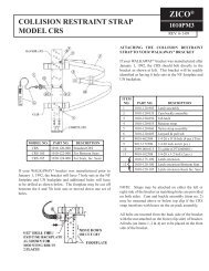
QUIC-LIFT Horizontal Ladder Access System<br />
Model HLAS<br />
ZICO ®<br />
3097PM6<br />
Parts and Instruction Manual REV. 2-11-14<br />
I. SYSTEMS AVAILABLE<br />
II.<br />
INSTALLING THE LADDER ACCESS SYSTEM<br />
A. Preparation for Mounting<br />
B. Electrical System<br />
C. Mounting Suggestions<br />
III.<br />
GENERAL INSTALLATION INFORMATION<br />
A. Mounting Points<br />
B. Electrical Control Panel<br />
C. Ladder Control Panel<br />
IV.<br />
STANDARD EQUIPMENT<br />
A. Instruction Packet<br />
B. Electrical Control Panel<br />
C. Ladder Control Panel<br />
V. OPTIONAL EQUIPMENT<br />
A. Model LAS-LGK Ladder Guard Kit<br />
B. Installation Rung Wear Sleeve<br />
VI.<br />
TROUBLESHOOTING<br />
A. Excess Movement of the Rack and Ladders<br />
B. Rack Moving in a Jerking Motion or Stops<br />
VII.<br />
MAINTENANCE<br />
A. Periodic<br />
B. Semi-Annually or at Scheduled Apparatus Lube Service<br />
C. Replacing Hydraulic Fluid in the System<br />
D. Replacing the Hydraulic Cylinder<br />
E. Replacing the Latch Limit Switch<br />
F. Pressure Washing<br />
VIII.<br />
IX.<br />
SERVICE<br />
WARRANTY<br />
X. DRAWINGS, DIAGRAMS AND CHARTS<br />
A. Basic System<br />
B. Electrical System<br />
C. Hydraulic System<br />
-1-
I. SYSTEMS AVAILABLE<br />
Systems for ladders are made to order according to the ladders to be carried. In order to provide the System<br />
you require, we need to know the manufacturer, model number and length of ladders to be carried. The following<br />
models are available according to the nested depth of the ladder combinations:<br />
• HLAS-975 Complete for 9-3/4" ladder combo<br />
• HLAS-1200 Complete for 12" ladder combo<br />
number:<br />
Systems for portable water tanks are designed for tanks up to 30" high. Specify the following model<br />
• HPTS<br />
NOTE:<br />
The following restrictions apply to both Systems<br />
• Systems are designed for ladders not exceeding 35' in length.<br />
• Systems are not designed for ladders with bangers or poles.<br />
• Maximum weight of ladders and other equipment carried on the ladder rack is not to<br />
exceed 500 pounds.<br />
The Systems are designed to operate in the following manner:<br />
A. The power switch on the ladder control panel should be turned to the "on" position. The green light<br />
will come on indicating power to the System. Press and hold down, on the "down" switch, to lower the<br />
System. The latch (9) will open freeing the booms to be lowered. The latch is controlled by an electric<br />
actuator (11). Press down on the control switch until the ladders are in the full down position, parallel to<br />
the vehicle. The electrical actuator will close the latch at the end of the cycle.<br />
B. To raise the unit, push "up" on the control switch and the booms will be raised. At the end of the<br />
cycle the latch will snap into place locking the booms in the closed position.<br />
C. The power switch should be turned to the "off" position (to conserve electrical power) when the<br />
ladders are not required.<br />
NOTE: For all part numbers in parenthesis, refer to Chart 1, page 26.<br />
-2-
II.<br />
INSTALLING THE LADDER ACCESS SYSTEM<br />
A. Preparation for Mounting<br />
The System has been tested at the factory prior to shipping. No additional adjustments should be<br />
required. However, the overall height of the unit, including the booms, is 56". The booms may need to be<br />
cut down in length for your application. A can of touch-up paint is available for this purpose. See<br />
drawings below to determine the required dimensions.<br />
*<br />
*<br />
SYM DESCRIPTION DIM. (MIN./MAX.)<br />
A shelf to bottom of ladder rack 38"/56"<br />
B shelf depth 12"/---<br />
C shelf width; door opening 15"/---<br />
D truck wall to bottom of rack (down pos.) 29-7/8"/47-7/8"<br />
*customer to cut boom to length required to obtain proper truck clearance.<br />
FIGURE 1<br />
REQUIRED DIMENSIONS<br />
HLAS SYSTEM<br />
Holes will need to be drilled in both booms to attach the boom extension weldments (left and right).<br />
See Figure 2.<br />
boom total length = dim "a" - 4/18"<br />
dim "a" = truck shelf to bottom of rack<br />
(formula for reference use only)<br />
FIGURE 2<br />
HOLE LOCATIONS<br />
TOP OF BOOMS<br />
-3-
A. Preparation for Mounting (continued)<br />
Plan and lay out the entire installation before making any cuts or drilling holes in the body of the<br />
fire apparatus. This will keep "out of service" time to a minimum and also help to minimize mistakes.<br />
Position the unit on the shelf of the apparatus and clamp it in place so that you can determine where<br />
the holes will be required for the mounting bolts. Also check to be sure there is an integral component of<br />
the body structure to attach the mounting bolts through. If there is no main frame member, you may have to<br />
add a 1/2" thick aluminum mounting plate and attach it to a main frame member. Place the ladders on top<br />
of the ladder rack.<br />
When the ladder is raised and lowered in this position, it should clear protruding objects on the<br />
apparatus, such as emergency light, hand rails, etc. Make sure that when the ladders are in the up position<br />
they do not obstruct cross lays on hose reels.<br />
In the event that the booms come into contact with the stiffening rib at the top of the vertical hose bed<br />
wall, you may have to notch out the stiffening rib to recess the HLAS System. If the stiffening rib must be<br />
notched, the exposed metal surfaces should be painted and covered with an edge guard material. In<br />
addition, if the stiffening rib is notched, you may wish to add a backing plate on the inside surface of the<br />
hose bed wall. The plate will reinforce the hose bed wall and provide a good mounting support for the<br />
vertical mounting holes, if used. The edges of the mounting plate should be rounded off on the side next<br />
to the hose, and flat head bolts should be used to mount the plate.<br />
Bolts 3/8", or larger, should be used to mount the base casting to the fire apparatus. When the unit<br />
will only be mounted to the hose bed wall or only to the shelf deck, 1/2" bolts should be used with<br />
substantial backing plates or attached to an integral component of the body structure.<br />
A ladder stop must be provided which will prevent the ladders from swaying when in the stored<br />
position. The stop may be fabricated using the top of the body panel as a starting point. The actual "stop"<br />
will be up to the body manufacturer to fabricate unless the optional Zico HLAS Stop, HLAS-OS, is<br />
ordered with your unit (optional stop shown in upper left of Figure 24, page 30).<br />
FIGURE 3<br />
LADDER STOP<br />
-4-
A. Preparation for Mounting (continued)<br />
A mechanism for opening the door panel in front of the unit must also be fabricated by the apparatus<br />
manufacturer. The actual mechanism will depend on whether the door opens down or to the side. Contact<br />
the factory for suggestions.<br />
B. Electrical System<br />
Now that you are sure of your mounting position, and the boom has been cut to the proper length, you<br />
may begin to lay out the electrical wiring (see Figure 6, page 6 and Figure 7, page 7). At this time it is a<br />
good idea to remove the unit from the apparatus shelf and clamp it to a work bench so that the booms can<br />
swing out away from the bench when lowered. Unit should be mounted the same distance back from the<br />
edge of the table as it would be on the shelf of your apparatus. Be sure the table is secured by adding a<br />
counterweight to the other side before lowering the unit. Determine where the wires can be run so they will<br />
not be visible from the outside of the apparatus. We recommend all electrical connections be soldered as<br />
this method is superior to crimp connections. We further recommend that a terminal block or quick<br />
disconnect be attached to the base casting. Wires from the hydraulic power unit (7), latch actuator (11) and<br />
limit switch (89) should go into the terminal block. This would facilitate service to these items if required.<br />
Measure the required run lengths of the wires. (See Figure 6, page 6 and Figure 7, page 7 for proper wire<br />
diameter.)<br />
Make up a wiring harness using wires longer than the required run lengths. Temporarily make all<br />
wire connections so you can test the system. With the table properly secured, you should be able to operate<br />
the unit.<br />
When the flashing light kit (model HLAS-FLK) must be installed, the wiring diagram and parts lists<br />
for the flashing lights may be found on pages 10 and 11, Figures 10 and 11.<br />
C. Removal of Shipping Plug<br />
Once the unit has been mounted to the apparatus, and the booms have been lowered completely,<br />
remove the Shipping Plug in the front of the reservoir (see Figure 4) and install the Breather with its filter<br />
facing down (see Figure 5).<br />
FIGURE 4<br />
FIGURE 5<br />
-5-
-6-<br />
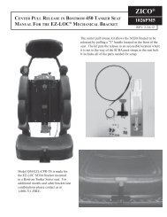
FIGURE 6<br />
WIRING DIAGRAM<br />
ELECTRIC/HYDRAULIC SYSTEM
PART NUMBER DESCRIPTION SOURCE QTY.<br />
3097-500-150 Sub-Panel, 8-1/4 x 8-1/4 1<br />
3097-500-151 Power Relay CR2A, CR2B, CR3A, CR3B Pokorny # R2624 4<br />
3097-500-155 Door Interlock Relay CR1 Pokorny # R2629 1<br />
3094-005-156 Control Relay CR4A, CR4B Pokorny # R2622 2<br />
3097-270-109 Flasher 552/536LL 1<br />
3097-500-181 Term. Block, 16 POS, Cinch 141 Series Newark # 28F881 1<br />
FIGURE 7<br />
FIELD WIRING DIAGRAM<br />
ELECTRIC/HYDRAULIC SYSTEM<br />
-7-
ITEM PART NUMBER DESCRIPTION QTY.<br />
1 3097-500-150 SUB-PANEL;8 1/4 x 8 1/4 1<br />
2 DIL-BLOX MODULE 1<br />
3 STANDOFF #74096 2<br />
4 SCREW, 10-32 x 1 1/2 PH 2<br />
5 LOCKWASHER #10 10<br />
6 HEX NUT, 10-32 10<br />
7 3097-500-151 POWER RELAY CR2A, CR2B, CR3A, CR3B 4<br />
8 3097-500-155 DOOR INTERLOCK RELAY CR1 1<br />
9 CONTROL RELAY CR4A, CR4B 2<br />
10 3097-270-109 FLASHER 1<br />
11 FUSE 7.5A 1<br />
12 LOCKWASHER #6 4<br />
13 HEX NUT, 6-32 4<br />
14 3097-500-181 TERM. BLOCK; 16 POS. CINCH 141 SERIES 1<br />
15 SCREW; 6-32 x 5/8 RD. HD. 4<br />
16 TERM. JUMPER CINCH TYP 141J 2<br />
17 WIRING SET 1<br />
18 TERMINAL LABEL 1<br />
19 TERMINAL MARKING 1<br />
FIGURE 8<br />
ELECTRICAL PANEL DIAGRAM<br />
ELECTRIC/HYDRAULIC SYSTEM<br />
-8-
-9-<br />
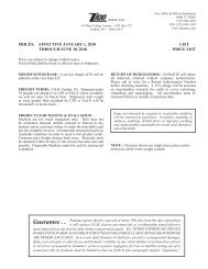
FIGURE 9<br />
HYDRAULIC CIRCUIT DIAGRAM
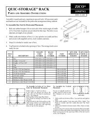
NFPA 1901-96 Standard requires flashing lights be provided, facing front and rear<br />
of apparatus. Lights must continue to flash while the device is out of the stored<br />
position. Beginning January 1, 1997, all systems are provided with flashing lights.<br />
The audio/visual alarm will continue to be offered as an option (see Section 8000<br />
for the audio/visual alarm). Drilled and tapped holes have been provided on<br />
QUIC-LIFT Systems shipped after January 1, 1997 to mount the light kits.<br />
ITEM<br />
NO. PART NO. DESCRIPTION QTY.<br />
87 3097-270-101 Clearance Light 2<br />
88 3097-270-106 Plate, Limit Switch* 1<br />
89 3097-270-105 Switch, Limit 1<br />
90 Harness, Limit switch (included with 89) 1<br />
91 9025-191108 Screw, 4-40 x 1/2" Rd. Hd. Phil. 4<br />
92 9025-191308 Screw, 6-32 x 5/16" Rd. Hd. Phil. 4<br />
93 3097-270-111 Cable Tie 6" 2<br />
94 3097-270-113 In Line Splice 7<br />
95 3097-510-110 16-2 Jacketed 2 Cond. Cable 1-6'<br />
96 3097-270-115 Snap Plug Connection* 4<br />
97 3097-500-172 Straight conn., Plastic, 1/2 NPT* 1<br />
98 8005-000-125 16 Ga. Lead Wire-Black 7.5'<br />
99 8005-000-130 16 Ga. Lead Wire-White 7.5'<br />
*Installed on unit<br />
WIRING DIAGRAM<br />
LIGHTS TO BE MOUNTED ON FORWARD<br />
& REAR FACE OF LADDER RACK<br />
FIGURE 10<br />
PARTS & WIRING DIAGRAM<br />
FLASHING LIGHT KIT<br />
-10-
WIRING SYSTEM:<br />
1. Lights are to be mounted on forward and rear face of<br />
ladder rack.<br />
2. Two six-foot lengths of wire (95) are provided and<br />
installed, one for each light. Wires run on the inside<br />
of the rack.<br />
3. One six-foot length of wire (95) provided to run<br />
from the switch (89) to the light wires (95). This<br />
wire should run-up through the right boom.<br />
4. Snap plug connections (96) will be attached to each<br />
wire, ready to plug into lights prior to mounting.<br />
FIGURE 11<br />
WIRING SYSTEM<br />
FLASHING LIGHT KIT<br />
-11-
C. Mounting Suggestions<br />
A "WARNING" label (part number 3097-000-110) is supplied with each QUIC-LIFT System. The<br />
pressure sensitive or metal label must be mounted in close proximity to the ladder control panel. All<br />
apparatus operators must be instructed to keep the area in front of the ladders clear of personnel when the<br />
System is being raised or lowered.<br />
Before starting the installation you should make sure you have all necessary tools and materials. This<br />
should include matching touch-up paint, edge trim (for cut outs), fender protector cloths and removable tape<br />
(to protect paint), necessary hardware, wire connectors, cable ties, burr remover, vacuum cleaner (for metal<br />
filings), loom (for wiring), drills, drill gun, wrenches, step ladders, etc. Be sure to allow yourself sufficient<br />
time to make a proper installation. You will probably have to remove the hose from the hose bed.<br />
NOTE: The hydraulic pump is designed for use in the normal operating termpature range of<br />
-20 to +160 degrees Fahrenheit. Please review your application with the factory for<br />
uses below -20 degrees.<br />
Following these simple instructions should make your installation easy and professional.<br />
III.<br />
GENERAL INSTALLATION INFORMATION<br />
The Ladder Access System was designed for ladders meeting the current NFPA 1931 standard. Systems<br />
accommodate most ladder combinations (see Section 1, under "NOTE" for exceptions).<br />
A. Mounting Points<br />
The HLAS unit should be positioned so that an equal number of rungs of the ladder extend on either<br />
side of the ladder rack. Mounting holes have been provided on both the vertical and horizontal mounting<br />
surfaces of the base casting. Although the device may be securely mounted from the horizontal surface<br />
only, it is a great advantage to be able to use mounting bolts on the vertical surface as well. The unit should<br />
be attached to an integral structural member of the vehicle. If this is not possible, then a one-half inch thick<br />
aluminum backing plate should be used. For mounting, 3/8" bolts should be used.<br />
B. Electrical Control Panel<br />
The electrical control panel should be mounted in a water-proof compartment.<br />
Several "Lock Out" circuits may be considered to prevent accidents from occurring. An ideal "Lock<br />
Out" system would only permit operation when the ignition switch is on, the transmission is in park, and<br />
any obstructing compartment doors are shut. Because of the higher amperage required to operate the<br />
System, a separate "Lock Out" circuit should be used. The "Lock Out" circuit should be separated from the<br />
QUIC-LIFT System circuit by a relay. This will prevent damage to the existing wiring system. The<br />
QUIC-LIFT System circuit should be protected by an 80 amp fuse (see Figure 6, page 6).<br />
-12-
C. Ladder Control Panel<br />
The ladder control panel should be mounted in such a position that the operator has full view of the<br />
QUIC-LIFT System and personnel that might come in contact with it (see Figure 13, page 14).<br />
Panel should be mounted in a waterproof compartment. After all connections are complete and<br />
system has been tested, protect connections with a weather proofer like liquid tape.<br />
We have extensively tested our QUIC-LIFT System and have found the normal life to be in excess of<br />
6,000 cycles without failure. With reasonable care and maintenance, your System should give you many<br />
years of excellent service.<br />
NOTE: Do not permit personnel to hang, sit or stand on the rack or ladders while they are<br />
stored on the QUIC-LIFT System. Permanent damage may result.<br />
IV.<br />
STANDARD EQUIPMENT<br />
The following items are included with each complete HLAS System:<br />
A. Instruction Packet<br />
Includes all information required to install a complete System. Wiring diagrams and parts lists are<br />
provided.<br />
B. Electrical Control Panel (79) P/N 3097-500-148<br />
Complete panel ready for mounting.<br />
FIGURE 12<br />
OVERALL DIMENSIONS AND COMPONENTS<br />
ELECTRICAL CONTROL PANEL<br />
-13-
C. Ladder Control Panel (80) P/N 3097-500-170<br />
Complete panel with an "on" and "off" switch and indicator light, and an "up" and "down" switch,<br />
ready for mounting.<br />
LT1 = Power Indicator Lamp P/N 3097-500-169<br />
S2 = Power Switch P/N 3097-500-157<br />
S1 = Control Switch P/N 3097-500-156<br />
Boot, Toggle Switch P/N 3097-105-145<br />
Name Plate (red) 3097-500-179<br />
Switch Plate (alum.) 3097-500-178<br />
FIGURE 13<br />
OVERALL DIMENSIONS AND COMPONENTS<br />
LADDER CONTROL PANEL<br />
FIGURE 14<br />
HANDLE ASSEMBLY<br />
ITEM PART NAME PART NUMBER QTY.<br />
82<br />
Housing - Medium 8.25" L 3097-165-125<br />
Housing - Full 10.5" L 3097-145-125<br />
1<br />
81 Handle 3097-105-109 1<br />
83 Spring 3097-105-113 1<br />
84 Screw 1/2-13 x 6-1/2 Socket Hd 9010-3350104 1<br />
109 Set Screw - 7/8-14 Hollow Lock 3097-105-118 1<br />
110 Ret. Ring, 1ø Ext. (5100-100) 3097-105-121 1<br />
111 Wear Strip 3097-105-160 1<br />
112 Support, Retainer Handle 3097-105-126 1<br />
113 Screw, 5/16-18 x 2 Socket Hd. 9010-333132 2<br />
85 Screw, 5/16-18 x 4-1/2 Sckt Hd. Gr 8 9018-103172 2<br />
100 Hex Nut, 5/16-18 Self Lock 9013-133100 4<br />
-14-
V. OPTIONAL EQUIPMENT<br />
The following items may be added to the HLAS Systems:<br />
A. Model LAS-LGK Ladder Guard Kit<br />
The ladder guard kit contains one tube of epoxy and two stainless steel guards. The guards may be<br />
attached to the ladder rung to prevent wear and possible damage as a result of the locking handle's contact<br />
with the rung. The new handle assemblies have a replaceable plastic wear pad which should prevent<br />
damage to the rungs, but the ladder guard kit may also be required if unnecessary wear is noted.<br />
Kit contains one tube of epoxy<br />
and two stainless steel rung<br />
protectors.<br />
Rung protector<br />
installed showing<br />
proper placement.<br />
FIGURE 15<br />
LADDER GUARD KIT<br />
B. Installation Rung Wear Sleeve<br />
The small plastic sleeves may be purchased directly from the ladder manufacturer. The sleeves are<br />
pop-riveted to the rungs and prevent unnecessary wear on the rungs from constant rubbing on the side rails.<br />
FIGURE 16<br />
RUNG WEAR SLEEVE<br />
-15-
VI.<br />
TROUBLESHOOTING<br />
All units are tested after final assembly to ensure proper operation and adjustment. No further adjustments<br />
should be required unless excess movement is noted.<br />
A. Excess Movement of the Rack and Ladders<br />
If the rack and ladders appear to be moving more than when the System was initially installed, it is<br />
probably due to one of the following reasons:<br />
1. Ladders and rack not properly seated against the vehicle mounted ladder stop.<br />
A ladder stop must be provided by the apparatus manufacturer to prevent the ladders from<br />
swaying. If the ladder rack is not touching the stop, swaying will occur. Shims may be required to<br />
close the gap.<br />
2. Booms move freely when the rack is pushed or pulled by hand.<br />
Use the following procedure for adjusting the hydraulic cylinder (8), bumpers (16) and latch (9).<br />
Refer to Figures 17 and 18 on page 17 for numbers in parenthesis.<br />
a. Remove ladders with the rack in the down position. Raise the unit back up approximately<br />
3/4 of the way and loosen the two bumper lock nuts (65). Turn the bumpers (16) towards the<br />
backing plate (6).<br />
b. Raise the rack up until the cylinder is fully extended and the latch (9) closes. The hydraulic<br />
pump will slow down when the cylinder is fully extended.<br />
c. Pull booms (2 and 3) out by hand to apply load on the cylinder (8).<br />
d. Check the gap between the inside face of the latch (9) and the outside face of the latch<br />
bar (10).<br />
The gap should be around 3/32" when pulling out on the boom assembly by hand to take the<br />
free play out of the unit. If the gap is less than 3/32", the overall length of the cylinder has to be<br />
lengthened. If the gap is more than 3/32", the overall length of the cylinder has to be made<br />
shorter.<br />
e. The length of the cylinder may be adjusted as follows:<br />
1. Loosen the 3/8" socket head cap screw clamp bolt on the shaft clevis pin.<br />
2. Lower the rack so the latch (9) opens and the latch bar (10) just clears the latch. This<br />
takes the pressure off the cylinder which will make the next step easier.<br />
-16-
A. Excess Movement of the Rack and Ladders (continued)<br />
3. Turn the cylinder shaft in the appropriate direction to lengthen or shorten it.<br />
WARNING:<br />
Do not use a pipe wrench or vise grips. Damage to the cylinder shaft<br />
will occur. The shaft will almost always turn by hand. Rubber coated<br />
work gloves will increase your grip.<br />
f. After turning the shaft about 1/4 turn, raise the unit back up. Do not tighten the clevis clamp<br />
bolt at this time.<br />
g. Make sure the cylinder is fully extended and re-check for the 3/32" gap while pulling out on<br />
the boom assemblies.<br />
FIGURE 17<br />
FRONT VIEW<br />
FIGURE 18<br />
SIDE VIEW<br />
h. After the 3/32" gap is achieved, tighten the clevis clamp bolt and turn the bumpers until they<br />
are touching the base casting (1). Maintain outward pressure on the boom while you are hand<br />
tightening the bumper.<br />
i. Lower the unit a few inches. Turn the bumpers out one full turn away from the backing<br />
plate. Re-tighten the bumper lock nuts (65).<br />
j. Raise the unit back up to full cylinder extension. Listen for the pump to slow down. The<br />
gap between the inside face of the latch (9) and the outside face of the latch bar (10) should now<br />
be 1/64" to 3/64" and the unit will be tight.<br />
-17-
B. Rack Moving in a Jerking Motion or Stops<br />
1. Check fluid level in the hydraulic pump.<br />
2. Follow filling procedure (VII. C. 1.).<br />
VII.<br />
MAINTENANCE<br />
A. Periodic<br />
1. Any time the ladder rack and ladders appear to sway, refer to Troubleshooting (VI. A.) and<br />
follow suggestions depending upon your specific problem.<br />
2. Visually inspect hydraulic system for leaks indicated by the presence of hydraulic fluid or the<br />
accumulation of dirt around a fitting. Refer to Checking Hydraulic Fluid Level (VII. B. 2.) before<br />
proceeding.<br />
3. Visually inspect the plastic pads for wear. Pads are located at several points on the ladder rack<br />
assembly and are designed to minimize wear to the ladders. Replace as required.<br />
B. Semi-Annually or at Scheduled Apparatus Lube Service<br />
The above items under Periodic Maintenance should be checked first and then proceed as follows:<br />
1. Lubricate the following parts as indicated.<br />
a. Joints and pivot points should be sprayed with CRC brand Stor&Lub long term lubricant<br />
and rust preventative #03032. Excess lubrication should be wiped off.<br />
b. Hydraulic ram is self-lubricating and should require no additional lubrication.<br />
c. Grease fittings are located on the bottom of the lower shaft (4), one on each side under the<br />
booms, and there is one additional grease fitting in the lower cylinder pin (57). Use chassis<br />
lube at these three points.<br />
d. Latch bar (10) and latch (9) should be lubricated with door jam grease where the two parts<br />
come together.<br />
-18-
FIGURE 19<br />
HYDRAULIC SYSTEM COMPONENTS<br />
B. Semi-Annually or at Scheduled Apparatus Lube Service (continued)<br />
2. Checking hydraulic fluid level.<br />
Hydraulic system is a closed loop system. No one, other than a qualified hydraulic pump<br />
technician, should attempt to remove any fittings or hoses from the system. The system contains<br />
one orifice which is restricted to .025" (30). Removal of this fitting could cause bodily injury.<br />
See location on Figure 22.<br />
a. The booms must be lowered completely to view oil level in reservoir.<br />
b. Remove Elbow (48) and Breather Filter from front of reservoir.<br />
-19-
B. Semi-Annually or at Scheduled Apparatus Lube Service (continued)<br />
c. View oil level through Breather/Fill Port. Oil should be 3/8" to 1/4" below the bottom of the<br />
Port.<br />
d. If oil needs to be added, Zico recommends:<br />
SAE 5W20, or other clean hydraulic oil with a viscosity of 150 to<br />
300 SUS at 100 degrees Fahrenheit. System capacity (dry) is<br />
50 ounces.<br />
C. Replacing Hydraulic Fluid in the System<br />
The whole procedure may take one to two hours. Have replacement reservoir seal and 50 ounces of<br />
fluid available before starting the job. Hydraulic fluid in this sytem may be under pressure. Always<br />
wear safety glasses and protective clothing and use the following procedure to change the fluid:<br />
1. Lower the booms and remove the ladder rack and ladders.<br />
2. Slowly remove the hydraulic lines from the fittings on the front side of the pump. See Figure 22.<br />
3. Disconnect the electric wires to the hydraulic pump.<br />
4. Remove the two bolts (45) and lock washers (73) holding the power unit mounting bar (32) to<br />
the base casting (1) and remove the power unit (7).<br />
5. Clamp the mounting bar (32) in a vise with the pump held in the vertical position (same as<br />
mounted position).<br />
6. With the pump mounted in the vise, remove the Breather Elbow (48) and Breather. Release the<br />
pump from the vise and drain oil into a pan via the Breather/Fill Hole. Loosen and remove the two<br />
screws holding the reservoir to the pump. Clean reservoir.<br />
7. Check the two filter screens in the bottom of the pump and clean if necessary.<br />
8. Place the two open hydraulic lines into a receptacle. Raise and lower the booms by hand to blow<br />
the fluid from the hydraulic cylinder (8).<br />
CAUTION:<br />
Control the raising and lowering of the booms. Do not allow them to drop<br />
uncontrolled.<br />
-20-
C. Replacing Hydraulic Fluid in the System (continued)<br />
9. Replace reservoir onto the bottom of the pump using new seal. Replace and tighten screws<br />
holding reservoir to pump.<br />
10. Re-attach the pump onto the base casting and re-attach the hydraulic lines and electric power.<br />
11. Put 32 ounces of fresh hydraulic fluid into the pump through the Breather/Fill Hole.<br />
12. Run the booms up and down three or four times. Bleed air from the lines the first time. Wait<br />
approximately 5 minutes and, with the booms down, check the fluid level. Approximately 18 ounces<br />
of fluid will have been replaced into the lines and hydraulic cylinder.<br />
13. Add 14 ounces of fluid to the reservoir, cycle system a few more times, and then recheck oil<br />
level. 1/8" to 1/4" below port is good.<br />
14. A couple of more ounces of fluid may have to be added to bring the fluid up. When the full level<br />
is obtained, reinstall Breather Elbow and Breather. Oil change complete.<br />
D. Replacing the Hydraulic Cylinder<br />
Elbow adapter fittings (30 & 31) are provided on replacement hydraulic cylinders. The elbow<br />
adapter with restricted orifice (30) should not be removed from the cylinder for any reason. Wearing<br />
safety glasses and protective clothing, you may use the following procedure to change the hydraulic<br />
cylinder:<br />
1. Make sure the latch (9) is securely in place. As a precaution, secure the booms to the apparatus<br />
so they cannot come down on their own.<br />
2. Remove the fluid lines (see Figure 19, page 19) from the elbow adapter fittings. Do not<br />
remove the elbow fittings from the cylinder. Place the open ends of the fluid lines into a<br />
receptacle to catch the fluid.<br />
3. Loosen the socket head cap screw on the lower side of the top clevis clamp. Note cylinder to<br />
clevis relationship.<br />
4. Remove pin (57) from the lower clevis clamp.<br />
5. Turn the cylinder counterclockwise to remove the cylinder ram from the top clevis clamp yoke.<br />
6. Replace the cylinder and turn clockwise to re-attach the cylinder ram into the top clevis clamp<br />
yoke.<br />
7. Replace pin (57) through the lower clevis clamp.<br />
8. Re-tighten the socket head cap screw on the lower side of the top clevis clamp; reattach the<br />
hydraulic lines, and remove the device used to secure the booms to the vehicle in step 1.<br />
-21-
D. Replacing the Hydraulic Cylinder (continued)<br />
9. CAUTION: The following instructions will leave boom rack uncontrolled. Manual control of<br />
boom will be necessary via fork lift or overhead crane. When ready, unlatch latch and lower boom<br />
all the way.<br />
10. Remove Breather Elbow (48) and Breather. Add oil to reservoir up to bottom of port.<br />
11. Slightly loosen the fitting on the bottom of the cylinder. Run the pump up to blow air out of the<br />
Up line. Retighten, and with the pump raise boom all the way up. Additional oil may be needed to<br />
achieve this.<br />
12. Slightly loosen the fitting at ram end of cylinder and run the pump to bleed air from the line.<br />
Retighten and run the system Down all the way.<br />
13. Add oil to the reservoir until it is 1/4" to 3/8" below the Fill Port. Run system a few more times,<br />
allowing air to settle out. Check oil level. When level is acceptable reinstall the Breather Elbow and<br />
Breather.<br />
14. Check the gap between the latch (9) and latch bar (10). If the gap is 1/64" to 3/64", you are<br />
done. If the gap is greater than this range, you will need to follow the steps under VI. A. 2.<br />
(page 16) to re-adjust the length of the cylinder ram.<br />
E. Replacing Latch Limit Switch<br />
The following procedure may be used to replace the latch limit switch:<br />
1. Lower the booms to gain access to the limit switch (12).<br />
2. Remove the old switch. Match the new switch to the old and set the roller follower arm on the<br />
same angle.<br />
3. Mount the new switch.<br />
4. With the booms up and the latch actuator retracted, lift up on the front of the latch (9) and<br />
listen for the latch limit switch to click. It should click when the bottom front side of the latch is<br />
approximately 1/4 to 3/8" above the top surface of the latch bar casting.<br />
5. To adjust the roller follower arm, loosen the Allen cap screw that locks this arm in place. Move<br />
this arm until the switch clicks with the 1/4 to 3/8" clearance.<br />
F. Pressure Washing<br />
Do not operate pressure washer around or near the hydraulic pump. Excessive pressure may allow<br />
soap and water to blow past the seal, damaging the hydraulic cylinder.<br />
VIII.<br />
SERVICE<br />
If you experience any problems with your Horizontal Ladder Access System, please call us at 800-711-3473<br />
for assistance. Please have the serial number of your system available. This number may be found on metal plate<br />
riveted to the base casting.<br />
-22-
IX.<br />
WARRANTY<br />
A copy of the warranty registration MUST be returned to ZICO to ensure registration of your System (see<br />
back cover).<br />
X. DRAWINGS, DIAGRAMS AND CHARTS<br />
A. Basic System<br />
1. Complete parts photos for HLAS (Figure 21, page 27 through Figure 24, page 30)<br />
2. Chart of HLAS component parts (Chart 1, page 26)<br />
3. Complete parts listing and drawing for HPTS (Figure 20, pages 24 and 25)<br />
4. Space requirement for system (Figure 1, page 3)<br />
5. Changing length of booms (Figure 2, page 3)<br />
6. Ladder stop (Figure 3, page 4)<br />
7. Handle assembly (Figure 14, page 14)<br />
8. Ladder guard kit (Figure 15, page 15)<br />
9. Rung wear sleeve (Figure 16, page 15)<br />
10. Adjustment procedure to arrest excessive movement (Figures 17 & 18, page 17)<br />
B. Electrical System<br />
1. Electrical control panel with mounting dimensions (Figure 12, page 13)<br />
2. Ladder control panel with mounting dimensions (Figure 13, page 14)<br />
3. Electrical diagrams (Figure 6, page 6 and Figure 7, page 7)<br />
4. Flashing light kit (Figure 10, page 10 and Figure 11, page 11)<br />
5. Latch limit switch (see VII. E., page 22, Figure 22, page 28)<br />
C. Hydraulic System<br />
1. Pump and hydraulic system (Figure 19, page 19)<br />
2. Restricted orifice fitting (Figure 19, page 19)<br />
-23-
ITEM NO. PART NO. DESCRIPTION QTY.<br />
1 3098-200-101 Rack Weldment 1<br />
2 3098-200-102 Safety Stop Bracket 2<br />
3 3098-200-104 Quick Release Strap Belt 2<br />
4 3097-500-415 Adjustable Side Guard 4<br />
5 9018-103744 Screw, 3/8-16 x 2 3/4 HH, C/S GR8 4<br />
6 9113-173700 Nut, 3/8-16 Nylon Lock Hex SS 4<br />
7 9114-103700 Flatwasher, 3/8 SS 8<br />
8 9018-102514 Screw, 1/4-20 x 7/8 HH, C/S GR8 4<br />
9 9113-172500 Nut, 1/4-20 Nylon Lock, Hex SS 4<br />
10 9114-102500 Flatwasher, 1/4 SS 8<br />
11 3097-500-421 Upright Wear Sleeves 4<br />
12 9018-103156 Screw, 5/16-18 x 3 1/2, HH GR8 8<br />
13 9014-113100 Flatwasher, 5/16 Nom 16<br />
14 9014-203100 Lockwasher, 5/16 Nom 8<br />
15 9113-103100 Hex Nut, 5/16-18 8<br />
FIGURE 20<br />
COMPONENTS FOR<br />
MODEL HPTS PORTABLE<br />
TANK SYSTEM<br />
-24-
-25-
ITEM PART NO. DESCRIPTION QTY.<br />
1<br />
2<br />
3<br />
4<br />
5<br />
6<br />
7<br />
8<br />
9<br />
10<br />
11<br />
12<br />
13<br />
14<br />
15<br />
16<br />
17<br />
18<br />
19<br />
21<br />
22<br />
23<br />
24<br />
25<br />
26<br />
27<br />
28<br />
29<br />
30<br />
31<br />
32<br />
33<br />
34<br />
35<br />
*36<br />
37<br />
38<br />
39<br />
40<br />
41<br />
42<br />
43<br />
44<br />
45<br />
46<br />
47<br />
48<br />
49<br />
50<br />
51<br />
52<br />
53<br />
54<br />
55<br />
56<br />
3097-500-101<br />
3097-500-103<br />
3097-500-105<br />
3097-500-115<br />
3097-500-109<br />
3097-500-111<br />
3097-500-192<br />
3097-500-198<br />
3097-500-193<br />
3097-500-121<br />
3097-500-185<br />
3097-500-181<br />
3097-500-187<br />
3097-500-189<br />
3097-500-191<br />
3097-500-113<br />
3097-500-195<br />
3097-605-196<br />
3097-500-407<br />
3097-500-419<br />
3097-500-420<br />
3097-500-424<br />
3097-500-418<br />
3097-500-415<br />
3097-500-421<br />
3097-500-135<br />
3097-500-133<br />
3097-500-132<br />
3097-500-134<br />
3097-500-129<br />
3097-500-125<br />
3097-500-124<br />
3097-500-190<br />
3097-500-162<br />
3097-500-164<br />
9018-104320<br />
9018-104372<br />
NOT PROVIDED<br />
9010-221310<br />
9010-221318<br />
9010-102524<br />
9018-103156<br />
9018-363128<br />
9010-163748<br />
9018-103744<br />
9010-103712<br />
9010-103716<br />
9018-103772<br />
3097-500-194<br />
9010-103148<br />
9010-383108<br />
0000-025-107<br />
9080-002516<br />
9080-002520<br />
9080-002528<br />
9080-005040<br />
3097-500-226<br />
Base Casting<br />
Boom-Left Hand<br />
Boom-Right Hand<br />
Lower Shaft, Boom<br />
Upper Mtg. Block Casting, Cyl.<br />
Backing Plate, Upper Mtg. Blk.<br />
Power Unit, Hydraulic<br />
Hyd. Cyl. 2.5" x 8" Stroke<br />
Latch<br />
Latch Bar<br />
Actuator, Latch 1ø x 1" Stroke<br />
Limit Switch, Latch<br />
Latch Spring Housing-Upper<br />
Latch Spring Housing-Lower<br />
Latch Spring<br />
Bumper, Mech. Stop<br />
Boom Ext Weldment-Left<br />
Boom Ext Weldment-Right<br />
Ladder Rack Weldment<br />
Safety Loop, 15" O.A.L.<br />
Safety Loop, 13" O.A.L.<br />
Sleeve, Safety Loop-28-1/2" Lg.<br />
Bracket, Safety Loop<br />
Adjustable Ladder Side Guard<br />
Upright Wear Sleeves-8-3/4"<br />
Elbow, PU to Hose (7/16-20)<br />
Hyd Flex Hose-Short - 20 3/4"L<br />
Hyd Flex Hose-Long - 29"L<br />
1/4 OD Hyd Line Assy.<br />
20 2<br />
Hydraulic Fluid, 1 Qt. NS<br />
Elbow/Adapter w/Orifice<br />
Elbow/Adapter<br />
Mtg. Bar, Power Unit<br />
Spin Drive Grease Fitting-1/4-28<br />
Spin Drive Grease Fitting-1/4-28 45°<br />
Screw, 7/16ø x 1-1/4 HH SZP Gr 8<br />
Screw, 7/16ø x 4 HH SZP Grade 8<br />
Base Mounting Screws NS<br />
Screw, #6-32 x 5/8 Pan Hd SZP<br />
Screw, #6-32 x 1-1/8 Pan Hd SZP<br />
Screw, 1/4-20 x 1-1/2" Hex Hd<br />
Screw, 5/16-18 x 3-1/2" Hx Hd<br />
SZP Grade 8<br />
Screw, 5/16-18 x 1-3/4" Flat Hd<br />
SZP Grade 8<br />
Screw, 3/8-16 x 3 FH-Phil SZP<br />
Screw, 3/8-16 x 2-3/4" Hex Hd<br />
SZP Grade 8<br />
Screw, 3/8-16 x 3/4" Hex Hd SZP<br />
Screw, 3/8-16 x 1 Hex Hd SZP<br />
Screw, 3/8-16 x 4-1/2" Hex Hd SZP<br />
Grade 8<br />
Plastic Elbow<br />
Screw, 5/16-18 x 3 Hex Hd SZP<br />
Setscrew 5/16-18 x 1/2" Cup Pt. Plated<br />
Boot, Red<br />
Clevis Pin, 1/4ø x 1 Lg. SZP<br />
Clevis Pin, 1/4ø x 1-1/4 Lg. SZP<br />
Clevis Pin, 1/4ø x 1-3/4 Lg. SZP<br />
Clevis Pin, 1/2ø x 2-1/2 Lg. SZP<br />
Cylinder Pin, 1"ø (Upper)<br />
1<br />
1<br />
1<br />
1<br />
1<br />
1<br />
1<br />
1<br />
1<br />
1<br />
1<br />
1<br />
1<br />
1<br />
1<br />
2<br />
1<br />
1<br />
1<br />
1<br />
2<br />
4<br />
4<br />
2<br />
1<br />
1<br />
1<br />
1<br />
1<br />
1<br />
1<br />
1<br />
2<br />
4<br />
4<br />
12<br />
2<br />
2<br />
1<br />
8<br />
2<br />
8<br />
4<br />
4<br />
4<br />
4<br />
1<br />
2<br />
1<br />
2<br />
1<br />
1<br />
1<br />
1<br />
1<br />
ITEM PART NO. DESCRIPTION QTY.<br />
57<br />
58<br />
59<br />
60<br />
61<br />
62<br />
63<br />
64<br />
65<br />
66<br />
67<br />
68<br />
69<br />
70<br />
71<br />
72<br />
73<br />
74<br />
75<br />
77<br />
78<br />
79<br />
80<br />
81<br />
82<br />
83<br />
84<br />
85<br />
86<br />
87<br />
88<br />
89<br />
90<br />
91<br />
92<br />
93<br />
94<br />
95<br />
96<br />
97<br />
98<br />
99<br />
100<br />
101<br />
102<br />
103<br />
104<br />
105<br />
106<br />
107<br />
109<br />
110<br />
111<br />
112<br />
113<br />
114<br />
115<br />
116<br />
117<br />
3097-500-126<br />
9070-000608<br />
9070-001212<br />
9070-001524<br />
9014-114300<br />
9113-172500<br />
9013-133100<br />
9012-103700<br />
9012-105000<br />
9012-154300<br />
9014-113100<br />
9014-113700<br />
9014-115000<br />
9014-201300<br />
3097-500-199<br />
9014-203100<br />
9014-203700<br />
9014-205000<br />
9014-204300<br />
3097-500-141<br />
3097-500-145<br />
3097-500-148<br />
3097-500-170<br />
3097-105-109<br />
3097-165-125<br />
3097-145-125<br />
3097-105-113<br />
9010-3350112<br />
9018-103172<br />
3097-105-116<br />
3097-270-101<br />
3097-270-106<br />
3097-270-205<br />
9025-191108<br />
9025-191305<br />
3097-270-111<br />
3097-270-113<br />
3097-510-110<br />
3097-270-115<br />
3097-500-172<br />
8005-000-125<br />
8005-000-130<br />
9013-133100<br />
3097-500-160<br />
9018-103172<br />
3097-290-105<br />
3097-500-423<br />
3097-500-425<br />
3097-500-427<br />
3097-500-174<br />
3097-105-118<br />
3097-105-121<br />
3097-105-160<br />
3097-105-126<br />
9010-333132<br />
3097-500-142<br />
3097-105-130<br />
3097-105-162<br />
3097-500-183<br />
Cylinder Pin, 1"ø (Lower)<br />
Cotter Pin, 1/6 x 1/2<br />
Cotter Pin, 1/8 x 3/4<br />
Cotter Pin 5/32 x 1-1/2<br />
Flatwasher, 7/16 ID SZP<br />
Lock Nut, 1/4-20 SZP<br />
Hex Nut, 5/16-18 SZP<br />
Hex Nut, 3/8-16 SZP<br />
Hex Nut, 1/2-13 SZP<br />
Hex Nut, 7/16-14 SZP<br />
Flatwasher, 5/16 ID SZP<br />
Flatwasher, 3/8 ID SZP<br />
Flatwasher, 1/2 ID SZP<br />
Lockwasher, #6 SZP<br />
Plug, Shipping<br />
Lockwasher, 5/16 ID SZP<br />
Lockwasher, 3/8 ID SZP<br />
Lockwasher, 1/2 ID SZP<br />
NS<br />
Lockwasher, 7/16 ID SZP (8)<br />
Helical Bundling Wrap-21" (9)<br />
Latch Act. 2 Wire Harness-7.5'<br />
Elec. Panel Assembly<br />
Switch Panel Assembly<br />
Handle, Ladder Retainer<br />
Retainer Housing - Medium - 8.25" L<br />
Retainer Housing - Full - 10.50"L<br />
Compression Spring<br />
Socket Hd Screw, 1/2-13 x 7<br />
Screw, 5/16-18 x 4 1/2 Socket Hd, GR 8<br />
Wear Pads<br />
Clearance Light<br />
Plate, Limit Switch<br />
Limit Switch<br />
Harness, Limit Switch (included w/89)<br />
Screw, #4-40 x 1/2 Self Tap Rnd Hd<br />
Screw, #6-32 x 5/16 Self Tap Rnd Hd<br />
Cable Tie, 6"<br />
In Line Splice<br />
16-2 Jacketed 2 Cond Cable<br />
Snap Plug Connector<br />
Straight Conn., Plastic, 1/2 NPT<br />
16 Ga Lead Wire - Black<br />
16 Ga Lead Wire - White<br />
Nut, Self Locking 5/16-18<br />
Ladder Rack Rubber Bumper<br />
Screw, 5/16-18 x 4 1/2 Hex Hd GR 8<br />
Paint, Touch Up, 12 Oz. Can<br />
Label, "danger, loss of hyd. fluid"<br />
Label, "warning, pinching of fingers"<br />
Label, "warning, striking injury"<br />
Cap, Plastic - 3/4ø Nom.<br />
Setscrew, 7/8-14 Hollow Lock<br />
Ret. Ring, 1ø Ext.<br />
Wear Strip<br />
Support, Retainer Handle<br />
Screw, 5/16-18 x 2 Socket Head<br />
Boom End Cap, Plastic<br />
Nylon Washer, 1/2 ID x 3/4 OD x .062<br />
Label, "to prevent wear"<br />
Tag, "Caution Remove Plug"<br />
NS<br />
NS<br />
(6)<br />
(6)<br />
NS<br />
NS<br />
NS<br />
NS<br />
1<br />
3<br />
1<br />
2<br />
8<br />
1<br />
12<br />
20<br />
4<br />
8<br />
24<br />
22<br />
4<br />
4<br />
1<br />
14<br />
22<br />
2<br />
8<br />
1<br />
1<br />
1<br />
1<br />
2<br />
2<br />
2<br />
2<br />
4<br />
8<br />
2<br />
1<br />
1<br />
1<br />
4<br />
2<br />
2<br />
6<br />
(3) 6'<br />
4<br />
1<br />
7'<br />
7'<br />
10<br />
2<br />
4<br />
1<br />
1<br />
1<br />
1<br />
2<br />
2<br />
2<br />
2<br />
2<br />
4<br />
2<br />
2<br />
1<br />
1<br />
NS - Not Shown on Figures 21 to 24<br />
*Indicates New Item<br />
( ) - See Figure _____<br />
Labels Not Shown<br />
CHART 1<br />
HLAS PARTS LISTING<br />
-26-
FIGURE 21<br />
HYDRAULIC COMPONENTS<br />
-27-
MODEL HLAS<br />
COMPONENT PARTS -<br />
HORIZONTAL LADDER<br />
ACCESS SYSTEM<br />
FIGURE 22<br />
HYDRAULIC AND ELECTRICAL<br />
LATCH COMPONENTS<br />
-28-
FIGURE 23<br />
BOOM COMPONENTS<br />
-29-
Optional Stop (sold separately)<br />
FIGURE 24<br />
END OF BOOM AND RACK COMPONENTS<br />
-30-
www.ziamatic.com<br />
<strong>Ziamatic</strong> <strong>Corp</strong>.<br />
TOLL FREE: 800-711-3473<br />
10 West College Avenue, P.O. Box 337, Yardley, PA 19067-0587 • (215) 493-3618 • FAX: (215) 493-1401<br />
*ZICO is a registered trademark for fire, safety and marine products made by <strong>Ziamatic</strong> <strong>Corp</strong>. Copyright <strong>Ziamatic</strong> <strong>Corp</strong>. 2-14<br />
-31-
WARRANTY REGISTRATION<br />
Please mail or fax a copy to ZICO to register your unit<br />
fire department name: ______________________________________ contact person: _______________________________<br />
phone no.: ______________________________________ fax no.: ______________________________________________________<br />
street address: _____________________________________________________________ p.o. box: ________________________<br />
city: ______________________________________________________ state ______________ zip: ______________________<br />
model no.: (check one) ___________ HLAS-975 ___________ HLAS-1200 ___________ HPTS<br />
serial no. on unit: (see page 25 for location)<br />
__________________________________________________<br />
INstalled on: (vehicle mfg.) ____________________________________ delivered: (date) _________________________<br />
was unit installed on: __________ new vehicle __________ retrofitted onto existing vehicle<br />
ladders mounted on the unit:<br />
duo safety _________ ft. extension, model _________<br />
duo safety _________ ft. roof, model _______________<br />
alco lite _________ ft. extension, model _________<br />
alco lite _________ ft. roof, model _______________<br />
duo safety _________ ft. __________, model _________ alco lite _________ ft. __________, model __________<br />
other (mfg.) __________________________________________________<br />
____________ ft. extension, model ____________<br />
____________ ft. roof, model __________________<br />
____________ ft. __________, model ____________<br />
where did you hear about our product?<br />
__________ magazine ad (specify) ________________________________________________________________________________<br />
__________ dealer (specify) ______________________________________________________________________________________<br />
__________ vehicle mfg. (specify) ________________________________________________________________________________<br />
__________ another department (specify) _______________________________________________________________________<br />
__________ other (specify) _______________________________________________________________________________________<br />
-32-