60-265: Fall 2010 Computer Architecture I: Digital Design Exercise 6 ...
60-265: Fall 2010 Computer Architecture I: Digital Design Exercise 6 ...
60-265: Fall 2010 Computer Architecture I: Digital Design Exercise 6 ...

You also want an ePaper? Increase the reach of your titles
YUMPU automatically turns print PDFs into web optimized ePapers that Google loves.
<strong>60</strong>-<strong>265</strong>: <strong>Fall</strong> <strong>2010</strong> <strong>Computer</strong> <strong>Architecture</strong> I: <strong>Digital</strong> <strong>Design</strong><br />
<strong>Exercise</strong> 6 – Sequential Circuits<br />
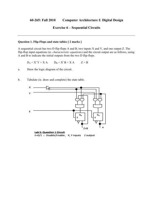
Question 1. Flip-Flops and state tables [ 2 marks ]<br />
A sequential circuit has two D flip-flops A and B, two inputs X and Y, and one output Z. The<br />
flip-flop input equations (ie. characteristic equations) and the circuit output are as follows, using<br />
A and B to indicate the initial outputs from the two D flip-flops.<br />
D A = X' Y + X A D B = X' B + X A Z = B<br />
a. Draw the logic diagram of the circuit.<br />
b. Tabulate (ie. draw and complete) the state table.
Question 2. Count-down Counter [ 4 marks ]<br />
<strong>Design</strong> a 2-bit count-down counter. This is a sequential circuit with two flip-flops and one input<br />
X. When X=0, the state of the flip-flops does not change. However, when X=1, the state<br />
sequence is 11, 10, 01, 00, then back to 11 and the sequence repeats. (Under normal use, X=1 is<br />
applied for a short time during which the circuit counts down by one to obtain the final stored<br />
result. Additional pulses of X=1 continue the counting down operation.)<br />
The state table is shown below:<br />
1<br />
This leads to the Boolean logic expressions:<br />
A + = X’A + X(AB + A’B’)<br />
B + = X’B + XB’
These expressions can be drawn as block circuit diagrams using AND-OR gates,<br />
or including XOR and XNOR gates. The A and B inputs on the right hand side<br />
are the original stored values in the flip-flops and the resulting expression values<br />
are fed back to the inputs of the flip-flops to produce the final outputs A + and B + .<br />
For this type of circuit the D type flip-flop is quite suitable.<br />
The block diagram is left as a straightforward exercise for students.<br />
Question 3. J-K Up-Down Counter [ 4 marks ]<br />
<strong>Design</strong> a sequential circuit with two J-K flip-flops A and B and two inputs E and X. If E=0, the<br />
circuit remains in the same state regardless of the value of X. When E=1 and X=1, the circuit<br />
goes "up" through the state transitions from 00 to 01 to 10 to 11 and back to 00, then repeating.<br />
When E=1 and X=0, the circuit goes "down" through the state transitions from 00 to 11 to 10 to<br />
01 back to 00, then repeating. (Note that if the E=1 and X inputs are applied only long enough to<br />
produce a single state transition, then a new set of inputs E=1 and the complement value of the<br />
previous X input is applied, the counter can be used to count up/down first, then count down/up).<br />
The state table is shown below:<br />
This leads to the Boolean logic expressions:<br />
A + = EX’(AB+A’B’) + EX(AB’+A’B) + E’A<br />
B + = EB’ + E’B<br />
These expressions can be drawn as block circuit diagrams using AND-OR gates,<br />
or including XOR and XNOR gates. The A and B inputs on the right hand side<br />
are the original stored values in the flip-flops and the resulting expression values<br />
are fed back to the inputs of the flip-flops to produce the final outputs A + and B + .
It is required that you use J-K flip-flops for this question. By connecting the<br />
expression outputs to the J-input, and the complement of the expression to the K-<br />
input, you basically transform the JK to a D type flip-flop.<br />
The block diagram is left as a straightforward exercise for students.<br />
© All information on this website is Copyright © <strong>2010</strong> by Robert D. Kent. All rights reserved.