Pickering Reed Relays - Pickering Interfaces
Pickering Reed Relays - Pickering Interfaces
Pickering Reed Relays - Pickering Interfaces

Create successful ePaper yourself
Turn your PDF publications into a flip-book with our unique Google optimized e-Paper software.
Product Catalogue<br />
<strong>Pickering</strong> <strong>Reed</strong> <strong>Relays</strong><br />
SoftCenter (Soft Inner Encapsulation)<br />
Built-In Mu-Metal Magnetic Screening<br />
Formerless Coils<br />
Highest Grade <strong>Reed</strong> Switches<br />
3 Volt Versions Now Available<br />
The <strong>Reed</strong> Relay Specialists<br />
www.pickeringrelay.com<br />
<strong>Pickering</strong> Electronics<br />
pickering
www.pickeringrelay.com<br />
Formerless Coil Winding on<br />
fully automatic machinery<br />
Life Testing to billions<br />
of operations<br />
100% Test with<br />
full traceability<br />
In-house designed and built<br />
Automation<br />
<strong>Pickering</strong> Electronics<br />
<strong>Pickering</strong> Electronics Ltd.<br />
Stephenson Road<br />
Clacton-on-Sea<br />
Essex<br />
CO15 4NL<br />
United Kingdom<br />
Tel: (UK) 01255 428141<br />
(International) +44 (0)1255-428141<br />
ISO9001<br />
Manufacture of <strong>Reed</strong> <strong>Relays</strong><br />
FM 29036<br />
Fax: (UK) 01255-475058<br />
(International) +44 (0)1255-475058<br />
E-Mail: sales@pickeringrelay.com<br />
Registered in England no. 857509 VAT no. GB103 5366 04<br />
Registered Offi ce: 335 City Road, London EC1V 1LJ<br />
In-house X-Ray<br />
facility
<strong>Pickering</strong> Electronics - A Brief History<br />
<strong>Pickering</strong> Electronics started in January 1968, with the aim to design and manufacture high quality reed relays, intended principally<br />
for use in Instrumentation and Test equipment.<br />
In the early 1970’s the Automatic Test Equipment (ATE) market started to take off and <strong>Pickering</strong> Electronics became the principal<br />
supplier to most UK ATE companies. In 1974 we moved to a new factory in Clacton-on-Sea.<br />
In 1981 we moved again to a purpose-built factory of 1000 square metres. The requirement for smaller and higher performance relays<br />
resulted in the launch of the SIL (Single-In-Line) relays in the early 1980’s. In 1986, we doubled the size of the factory to 2000<br />
square metres.<br />
Today, our SIL range is by far the most developed in the relay industry with relays 25% the size of many of our competitors. The<br />
small SIL relays are sold in high volumes to large ATE companies throughout the world.<br />
<strong>Pickering</strong> is a privately owned company and currently employs about 150 people. The company owns the freehold of its main two<br />
acre site and factory, with no mortgages or borrowings, so we have a very strong financial base.<br />
<strong>Pickering</strong> Electronics gained ISO9002 approval in August 1994.<br />
CONTENTS<br />
Clicking on the Relay Type that interests you takes you to the associated Data Sheet.
<strong>Pickering</strong> Electronics<br />
manufacture many hundreds<br />
of special reed relay types.<br />
If you do not see exactly what<br />
you require, please contact<br />
our technical sales offi ce. We<br />
may already have it available<br />
or be able to design and<br />
manufacture it for you.<br />
Please telephone<br />
+44 (0)1255 428141<br />
or fax<br />
+44 (0)1255 475058<br />
or email<br />
sales@pickeringrelay.com
Soft Centres (SoftCenter )<br />
<strong>Pickering</strong> reed relays are encapsulated using a soft inner material to greatly reduce physical stresses on the glass/metal seal of the reed switch capsule. Different<br />
materials have different expansion characteristics and the very hard compounds used by most manufacturers can cause stresses that can damage seals or distort the<br />
reed switch thereby changing switch blade alignment. This will degrade contact resistance stability and life expectation.<br />
Built in, Mu-Metal Magnetic Screening<br />
<strong>Reed</strong> switches are operated by the magnetic fi eld from a coil which is wound around the reed switch capsule. Without a magnetic screen, this fi eld will spread some<br />
way outside the confi nes of the relay package and will de-sensitize other reed relays mounted alongside. As an example, an unscreened relay mounted on 0.2 inches<br />
(5.08mm) pitch, will require a coil voltage about 25 percent higher to operate it, when other relays alongside are also in an operated state.<br />
This falls to between 1 and 5 percent, according to type, if magnetically screened. Smaller <strong>Pickering</strong> relays on 0.15 inches (3.81mm) pitch, would have an interaction<br />
fi gure as high as 40 percent if unscreened. The effect of magnetic interaction is compounded when temperature is also considered.<br />
The operating coil is wound using copper wire which has a co-effi cient of resistance of approximately 0.4 percent per degree Centigrade. This means that a temperature<br />
increase of 50 degrees Centigrade will increase the coil resistance by a further 20 percent. The coil current and therefore the level of magnetic fi eld, will fall by this<br />
same amount. A corresponding increase in drive voltage will therefore be required to generate the necessary magnetic fi eld to operate the reed switch. MAGNETIC<br />
SCREENING IS ABSOLUTELY ESSENTIAL FOR SMALL REED RELAYS.<br />
Formerless Coils<br />
Relay operating coils are commonly wound on bobbins. The great majority of <strong>Pickering</strong> relays are manufactured with self supporting coils, thus avoiding the space<br />
required for these bobbins. In the case of the smaller relays types, this gives around 50 percent more room for the coil winding, allowing the use of less sensitive<br />
reed switches with their inherent advantages of higher operating and restoring forces. In some ranges, this technique allows <strong>Pickering</strong> to achieve extremely high coil<br />
resistance fi gures.<br />
Highest Grade <strong>Reed</strong> Switches<br />
<strong>Pickering</strong> relays feature the very highest quality ‘instrumentation grade’ reed switches to meet the exacting demands and long life required of today’s equipment<br />
manufacturers. <strong>Pickering</strong> relays are 100 percent tested for all operating parameters including, operate and release voltages, operate, release and contact bounce times,<br />
contact resistance, contact resistance stability and insulation resistance.<br />
How To Get The Best From <strong>Reed</strong> <strong>Relays</strong><br />
If used correctly a reed relay is a superbly reliable device. The switch contacts are hermetically sealed and do not suffer from oxidization in the same way as an open<br />
electro-mechanical relay. If you follow the tips below, it will help you to achieve a reliable design with a long life.<br />
Life Expectancy<br />
In typical applications, for example, switching 10 volts at 10 mA, the life of dry reed relays will be in excess of 100 million operations. We can help you to choose the best<br />
relay for your application.<br />
Calculate how many operations you require from the relay. If it is operated once a second, 24 hours a day, it is worth noting that there are about 31.5 million seconds in a<br />
year. The most common reliability problems are caused by abusive loads. - Read On!<br />
Capacitive Loads<br />
When capacitive loads are switched, there is a danger that the initial surge current will exceed the rating of the switch, thereby shortening the life of the relay. To prevent<br />
this, a surge limiting device, the most simple being a resistor, should be used. Long cable runs should also be considered, they can sometimes have a surprisingly high<br />
capacitance.<br />
Inductive Loads<br />
Arcing can occur when a reed switch is used to break a current to an inductive load. The back EMF can cause contact damage and should be eliminated by the use of<br />
an RC snubber, varistor or in the case of a DC load, a diode. Contact our technical department for further details.<br />
Lamp Loads<br />
A tungsten fi lament lamp may have an inrush of up to 10 times its steady state current. Surge current should be limited to the rating of the relay with a resistor. This will<br />
also increase the life of the lamp.<br />
Coil Data<br />
The standard must ‘operate’ and & ‘must release’ voltages of <strong>Pickering</strong> relays at 25 degrees Centigrade are 75 percent and 10 percent of the nominal coil voltage, that is<br />
3.75 volts and 0.5 volts for a 5 volt relay.<br />
The copper coil wire has a positive temperature coeffi cient of approximately 0.4 percent per degree Centigrade. If the temperature increases by 50 degrees Centigrade,<br />
the voltage required to operate the relay will increase by around 20 percent.<br />
The operate voltage is also effected by the extraneous magnetic fi elds from adjacent relays. Most <strong>Pickering</strong> relays feature an internal mu-metal magnetic screen to<br />
eliminate this problem.<br />
Operate Times<br />
The typical operate time of a dry reed relay is between 250 microseconds and 1 millisecond, depending on switch type. The Form A (energize to make) types in the small<br />
Single-in-Line relays are the fastest, typically 250 microseconds.<br />
The release time is typically one half of the operate time. For more specifi c information, please contact our technical department.<br />
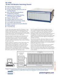
The Advantages of <strong>Pickering</strong> <strong>Reed</strong> <strong>Relays</strong><br />
TYPICAL PICKERING CONSTRUCTION<br />
TYPICAL COMPETITOR’S CONSTRUCTION<br />
Encapsulation<br />
Shell<br />
Encapsulation<br />
Shell<br />
Internal mu-metal<br />
magnetic screen<br />
Soft inner<br />
encapsulation<br />
material<br />
to protect<br />
reed switch<br />
Very hard<br />
moulding material<br />
Coil winding<br />
Internal mu-metal magnetic screen<br />
permitting high packing density without<br />
magnetic interaction<br />
<strong>Reed</strong> switch<br />
Delicate glass/metal<br />
reed switch seal.<br />
Must be protected<br />
Former-less Self supporting<br />
operating coil coil to maximise<br />
magnetic drive<br />
Diode<br />
Instrumentation grade<br />
reed switch<br />
Hard outer<br />
encapsulation<br />
material<br />
<strong>Pickering</strong><br />
SoftCenter<br />
Construction<br />
Diode<br />
No mu-metal<br />
magnetic screen<br />
High magnetic<br />
interaction<br />
with adjacent<br />
relays<br />
Coil supporting bobbin,<br />
wastes space and<br />
reduces magnetic drive
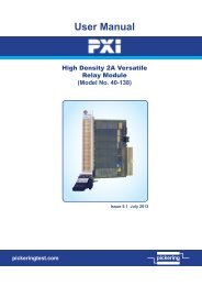
PICKERING SERIES 200<br />
Surface Mount <strong>Reed</strong> <strong>Relays</strong><br />
Including coaxial types for up to 5GHz<br />
New<br />
3 Volt<br />
Version<br />
FEATURES<br />
• z SoftCenter construction<br />
•z Highest quality instrumentation grade switches<br />
•z Encapsulated in plastic package with internal<br />
mu-metal screen for side-by-side mounting<br />
without magnetic interaction<br />
12<br />
• z Insulation resistance greater than 10 ohms for<br />
Form A devices<br />
•z Dry and mercury wetted switches available<br />
•z Wide range of switch configurations - 1 Form A,<br />
1 Form B, 2 Form A and 1 Form C<br />
•z For R.F. or high speed digital applications, 50<br />
or 75 ohms coaxial devices are available in the<br />
same small package<br />
•z 3, 5, and 12 volt coils are standard, with or<br />
without internal diode<br />
•z 100% tested for dynamic contact resistance<br />
The Series 200 is a complete range of surface mount reed relays.<br />
Both dry and mercury wetted switches are available in a wide<br />
range of configurations including coaxial types for RF up to<br />
5GHz, or high speed digital switching with a step response time<br />
of less than 30ps. Please contact our technical department for<br />
supplementary RF data.<br />
The special high temperature plastic package will withstand<br />
the temperatures associated with Infra-red or vapour phase<br />
reflow soldering processes. A flexible inner encapsulant protects<br />
the sensitive glass/metal reed switch seals - this is a very big<br />
advantage over the more usual hard moulded package.<br />
Switch Ratings - Dry Switches<br />
•z<br />
•z<br />
•z<br />
•z<br />
•z<br />
•z<br />
•z<br />
1 Form A (energize to make), 10 watts at 200V<br />
1 Form A (energize to make), 15 watts at 200V<br />
1 Form A (energize to make), 10 watts at 500V<br />
Coaxial 50Ω (energize to make), 10 watts at 200V<br />
Coaxial 75Ω (energize to make), 10 watts at 200V<br />
1 Form B (energize to break), 10 watts at 200V<br />
1 Form C (change-over), 3 watts at 200V<br />
•z 2 Form A (energize to make), 10 watts at 200V<br />
Switch Ratings - Mercury Wetted Switches<br />
•z 1 Form A (energize to make), 50 watts at 500V<br />
•z<br />
1 Form A (Position insensitive), 30 watts at 350V<br />
15.25 (0.6)<br />
15.25 (0.6)<br />
PICKERING ELECTRONICS<br />
2 0 0 - 1 - A - 5 / 2 D<br />
PICKERING ELECTRONICS<br />
20.0 (0.79)<br />
2 0 0 - 2 - A - 5 / 2 D<br />
UP<br />
200-1-A-5/ 6 D<br />
PICKERING ELECTRONICS<br />
3.90 (0.154)<br />
4.0mm max.<br />
6.8<br />
Max<br />
(0.27)<br />
17.25 (0.68)<br />
PICKERING ELECTRONICS<br />
200RF 50-1-A-5/ 2 D<br />
1 Form A Co-axial<br />
5.85 (0.23)<br />
6.0mm max.<br />
6.8<br />
Max<br />
(0.27)<br />
17.25 (0.68)<br />
PICKERING ELECTRONICS<br />
UP<br />
2 0 0 - 1 - B - 5 / 2 D<br />
2 Form A 1 Form B<br />
22.0 (0.87)<br />
5.85 (0.23)<br />
6.0mm max.<br />
9.0<br />
Max<br />
(0.35)<br />
1 Form A<br />
High voltage<br />
Dry or Mercury<br />
15.25 (0.6)<br />
15.25 (0.6)<br />
20.0 (0.79)<br />
200-1-C-5/ 7 D<br />
PICKERING ELECTRONICS<br />
UP<br />
PICKERING ELECTRONICS<br />
Clacton-on-Sea, England<br />
200-1-C-5/ 7 D<br />
1 Form C<br />
Dry<br />
3.90 (0.154)<br />
4.0mm max.<br />
6.8<br />
Max<br />
(0.27)<br />
17.25 (0.68)<br />
5.85 (0.23)<br />
6.0mm max.<br />
6.8<br />
Max<br />
(0.27)<br />
17.25 (0.68)<br />
22.0 (0.87)<br />
5.85 (0.23)<br />
6.0mm max.<br />
9.0<br />
Max<br />
(0.35)<br />
Dimensions in Millimetres (Inches in brackets)<br />
www.pickeringrelay.com<br />
www.pickeringrelay.com<br />
pickering<br />
200/06/09
www.pickeringrelay.com<br />
Dry <strong>Reed</strong> - Series 200 switch ratings<br />
The contact ratings for each switch type are shown below:<br />
Sw. Switch<br />
No form<br />
Power<br />
rating<br />
Max.<br />
switch current<br />
Max.<br />
carry current<br />
Max.<br />
switching volts<br />
Dry Relay - Coil data and type numbers<br />
Special<br />
Features<br />
1 A 15 Watts 0.75 Amp. 1.2 Amp. 200 General purpose<br />
2 A or B 10 Watts 0.5 Amp. 1.2 Amp. 200 Low level<br />
3 C 3 Watts 0.25 Amp. 1.2 Amp. 200 Change over<br />
4 A 10 Watts 0.5 Amp. 1.2 Amp. 500 High Voltage<br />
Switch no.2 is particularly good for switching low currents and/or voltages. It is<br />
the ideal switch for Automatic Test Equipment where cold switching techniques<br />
are often used. Where higher power levels are involved, switch no.1 is a more<br />
suitable choice.<br />
Device description Type number Coil (V)<br />
1 Form A (energize to make)<br />
General Purpose Sw. No. 1<br />
1 Form A (energize to make)<br />
Low Level Switch No. 2<br />
1 Form A 50 ohms coaxial<br />
Low Level Switch No. 2<br />
1 Form A 75 ohms coaxial<br />
Low Level Switch No. 2<br />
1 Form A (energize to make)<br />
High Voltage Switch No. 4<br />
1 Form C (change-over)<br />
Switch No. 3<br />
1 Form B (energize to break)<br />
Low Level Switch No. 2<br />
2 Form A (energize to make)<br />
Low Level Switch No. 2<br />
When an internal diode is required, the suffix D is added to the part number as<br />
shown in the table. If a diode is not required, the D suffix should be omitted.<br />
Mercury <strong>Reed</strong> - Series 200 switch ratings<br />
The contact ratings for each switch type are shown below:<br />
Sw. Switch<br />
No form<br />
Power<br />
rating<br />
Max.<br />
switch current<br />
Max.<br />
carry current<br />
Max.<br />
switching volts<br />
Mercury Relay - Coil data and type numbers<br />
Special<br />
Features<br />
6 A 50 Watts 2 Amp. 3 Amp. 500 Standard Mercury<br />
8 A 30 Watts 0.75 Amp. 2 Amp. 350<br />
Position<br />
Insensitive<br />
Device<br />
type<br />
1 Form A (energize to make)<br />
Switch No. 6<br />
1 Form A (energize to make)<br />
Position Insensitive Switch No. 8<br />
200-1-A-5/1D<br />
200-1-A-12/1D<br />
200-1-A-3/2D<br />
200-1-A-5/2D<br />
200-1-A-12/2D<br />
200RF50-1-A-5/2D<br />
200RF50-1-A-12/2D<br />
200RF75-1-A-5/2D<br />
200RF75-1-A-12/2D<br />
200-1-A-5/4D<br />
200-1-A-12/4D<br />
200-1-C-5/3D<br />
200-1-C-12/3D<br />
200-1-B-5/2D<br />
200-1-B-12/2D<br />
200-2-A-5/2D<br />
200-2-A-12/2D<br />
Type Number<br />
200-1-A-5/6D<br />
200-1-A-12/6D<br />
200-1-A-5/8D<br />
200-1-A-12/8D<br />
Coil<br />
voltage<br />
5<br />
12<br />
5<br />
12<br />
Coil Max. contact<br />
resistance resistance (initial)<br />
140<br />
500<br />
140<br />
500<br />
0.075 Ohms<br />
0.075 Ohms<br />
0.100 Ohms<br />
0.100 Ohms<br />
When an internal diode is required, the suffix D is added to the part number as<br />
shown in the table. If a diode is not required, the D suffix should be omitted.<br />
5<br />
12<br />
3<br />
5<br />
12<br />
5<br />
12<br />
5<br />
12<br />
5<br />
12<br />
5<br />
12<br />
5<br />
12<br />
5<br />
12<br />
Coil resist.<br />
(ohms)<br />
500<br />
1000<br />
250<br />
500<br />
1000<br />
250<br />
600<br />
250<br />
600<br />
500<br />
1000<br />
500<br />
1000<br />
750<br />
1000<br />
400<br />
1000<br />
Contact resist.<br />
max. (initial)<br />
0.15Ω<br />
0.15Ω<br />
0.12Ω<br />
0.12Ω<br />
0.12Ω<br />
0.12Ω<br />
0.12Ω<br />
0.12Ω<br />
0.12Ω<br />
0.15Ω<br />
0.15Ω<br />
0.20Ω<br />
0.12Ω<br />
0.12Ω<br />
0.12Ω<br />
0.12Ω<br />
Package<br />
Number<br />
1<br />
1<br />
2<br />
2<br />
5<br />
6<br />
4<br />
3<br />
Pin configuration and dimensional data<br />
Dimensions in Millimetres (Inches in brackets).<br />
1 Form A (Energize to make)<br />
Package Number 1<br />
Schematic<br />
shown from<br />
top of relay<br />
Orientation<br />
spot printed<br />
on this corner<br />
1 Form A (Coaxial)<br />
Package Number 2<br />
Schematic<br />
shown from<br />
top of relay<br />
Orientation<br />
spot printed<br />
on this corner<br />
2 Form A (Energize to make)<br />
Package Number 3<br />
Schematic<br />
shown from<br />
top of relay<br />
Orientation<br />
spot printed<br />
on this corner<br />
1 Form B (Energize to break)<br />
Package Number 4<br />
Schematic<br />
shown from<br />
top of relay<br />
Orientation<br />
spot printed<br />
on this corner<br />
1 Form A (Energize to make)<br />
Package Number 5<br />
Schematic<br />
shown from<br />
top of relay<br />
Orientation<br />
spot printed<br />
on this corner<br />
1 Form C (Changeover)<br />
Package Number 6<br />
Schematic<br />
shown from<br />
top of relay<br />
Orientation<br />
spot printed<br />
on this corner<br />
Mercury wetted<br />
versions this way up<br />
2.0<br />
(0.08)<br />
6.8<br />
Max.<br />
(0.27)<br />
1.0<br />
pitch<br />
(0.04)<br />
6.8<br />
Max.<br />
(0.27)<br />
2.0<br />
pitch<br />
(0.08)<br />
6.8<br />
Max.<br />
(0.27)<br />
4.0<br />
(0.16)<br />
6.8<br />
Max.<br />
(0.27)<br />
4.0<br />
(0.16)<br />
9.0<br />
Max.<br />
(0.35)<br />
2.0<br />
pitch<br />
(0.08)<br />
9.0<br />
Max.<br />
(0.35)<br />
20.0 (0.79)<br />
PICKERING - England<br />
2 0 0 - 1 - C - 5 / 3 D<br />
1.0 (0.04)<br />
Order Code<br />
The following example indicates data required to process your<br />
order promptly:<br />
200 - 1 - A - 5 / 2 D<br />
0.25<br />
(0.01)<br />
0.25<br />
(0.01)<br />
0.25<br />
(0.01)<br />
0.25<br />
(0.01)<br />
0.25<br />
(0.01)<br />
15.25 (0.6)<br />
PICKERING - England<br />
2 0 0 - 1 - A - 5 / 1 D<br />
0.25<br />
(0.01)<br />
15.25 (0.6)<br />
PICKERING - England<br />
200RF50-1-A-5 / 2D<br />
15.25 (0.6)<br />
PICKERING - England<br />
2 0 0 - 2 - A - 5 / 2 D<br />
15.25 (0.6)<br />
PICKERING - England<br />
2 0 0 - 1 - B - 5 / 2 D<br />
20.0 (0.79)<br />
PICKERING - England<br />
200-1-A-5 / 6D<br />
UP<br />
1.0 (0.04)<br />
1.0<br />
(0.04)<br />
1.0 (0.04)<br />
1.0<br />
(0.04)<br />
1.0 (0.04)<br />
1.0<br />
(0.04)<br />
1.0 (0.04)<br />
1.0<br />
(0.04)<br />
1.0 (0.04)<br />
1.0<br />
(0.04)<br />
1.0<br />
(0.04)<br />
0.50<br />
(0.02)<br />
3.90<br />
(0.154)<br />
1.0<br />
(0.04)<br />
0.40<br />
(0.016)<br />
3.90<br />
(0.154)<br />
Mercury <strong>Relays</strong><br />
With the exception of the position insensitive type, mercury<br />
relays should be mounted vertically in the direction of the arrow.<br />
4.0mm<br />
max.<br />
1.0<br />
(0.04)<br />
4.0mm<br />
max.<br />
0.50<br />
(0.02)<br />
1.0<br />
(0.04)<br />
0.50<br />
(0.02)<br />
1.0<br />
(0.04)<br />
5.85<br />
(0.23)<br />
6.0mm<br />
max.<br />
5.85<br />
(0.23)<br />
6.0mm<br />
max.<br />
0.50<br />
(0.02)<br />
1.0<br />
(0.04)<br />
0.50<br />
(0.02)<br />
1.0<br />
(0.04)<br />
5.85<br />
(0.23)<br />
6.0mm<br />
max.<br />
5.85<br />
(0.23)<br />
6.0mm<br />
max.<br />
<strong>Pickering</strong> Electronics Limited<br />
Stephenson Road<br />
Clacton-on-Sea<br />
CO15 4NL<br />
England<br />
email: sales@pickeringrelay.com<br />
Tel. (UK) 01255 428141<br />
(International) +44 1255 428141<br />
Fax. (UK) 01255 475058<br />
(International) +44 1255 475058<br />
ISO9001<br />
Manufacture of <strong>Reed</strong> <strong>Relays</strong><br />
FM 29036<br />
Series<br />
Number of reeds<br />
Switch form<br />
Coil voltage<br />
Switch number (See table adjacent)<br />
Diode if fitted (Omit if not required)<br />
Help !!!<br />
If you need any technical advice or help in any way, please telephone our<br />
Technical Sales Department. There is a limit to how much data we can put<br />
on a sales leaflet and we will always be pleased to discuss <strong>Pickering</strong> reed<br />
relays with you.<br />
Please ask us for a FREE evaluation sample<br />
www.pickeringrelay.com<br />
pickering
118-1-A-5/2D<br />
PICKERING SERIES 118<br />
High Coil Resistance<br />
Single-in-Line reed relays<br />
Stacks on 0.2 x 0.33 inches pitch<br />
New<br />
3 Volt<br />
Version<br />
FEATURES<br />
• SoftCenter construction (see opposite)<br />
• Highest quality instrumentation grade switches<br />
• Sputtered ruthenium switches rated at 10 Watts,<br />
0.5 A or 15 Watts, 0.75 A<br />
• Plastic package with internal mu-metal magnetic<br />
screen<br />
• They take up very little board area, conserving<br />
space<br />
• Insulation resistance greater than 10 12 Ω<br />
• 100% tested for dynamic contact resistance for<br />
guaranteed performance<br />
The <strong>Pickering</strong> Series 118 is a range of very sensitive reed<br />
relays that are ideal for portable electronic instruments<br />
or other applications where low power consumption and<br />
a very small footprint is important. They have 5 volt coils<br />
with a resistance up to 2200 Ω and the option of an<br />
internal diode.<br />
Two switch types are available. Switch type number 1<br />
is better suited for general purpose applications. Switch<br />
type 2 is better suited to low level or 'cold' switching.<br />
Both types feature high quality, instrumentation grade<br />
switch contacts and require a board area of only 0.2 x<br />
0.33 inches (5.1 x 8.4 mm).<br />
These relays feature internal mu-metal magnetic screens.<br />
Mu-metal has the advantage of a high permeability and<br />
low magnetic remanence and eliminates problems that<br />
would otherwise occur due to magnetic interaction.<br />
<strong>Relays</strong> of this size without magnetic screening would be<br />
totally un suit able for ap pli ca tions where dense packing is<br />
required.<br />
Initially, single pole versions only are available in this<br />
range but double pole versions will follow in the future.<br />
0.32 nominal (8.13)<br />
0.33 maximum (8.38)<br />
Pin 1<br />
PICKERING<br />
0.19 nominal (4.80)<br />
0.20 maximum (5.08<br />
0.6 nominal (15.24)<br />
0.61 maximum (15.5)<br />
Dimensions in Inches<br />
(Millimetres in brackets)<br />
<strong>Pickering</strong> SoftCenter Construction<br />
TYPICAL PICKERING CONSTRUCTION<br />
Encapsulation<br />
Shell<br />
Internal mu-metal magnetic screen<br />
permitting high packing density without<br />
magnetic interaction<br />
Delicate<br />
glass/metal<br />
reed switch seal.<br />
Must be<br />
protected<br />
Internal<br />
mu-metal<br />
magnetic<br />
screen<br />
Bobbinless<br />
self<br />
supporting<br />
coil to<br />
maximise<br />
magnetic drive<br />
Diode<br />
Encapsulation<br />
Shell<br />
Former-less<br />
operating coil<br />
Instrumentation<br />
grade<br />
reed switch<br />
Soft inner<br />
encapsulation<br />
material<br />
to protect<br />
reed switch<br />
<strong>Reed</strong> switch<br />
Diode<br />
PICKERING<br />
118-1-A-5/2D<br />
Actual size<br />
TYPICAL COMPETITOR’S CONSTRUCTION<br />
Very hard<br />
moulding material<br />
No mu-metal<br />
magnetic screen<br />
High magnetic<br />
interaction<br />
with adjacent<br />
relays<br />
Coil winding<br />
www.pickeringrelay.com<br />
Hard outer<br />
encapsulation<br />
material<br />
Coil supporting<br />
bobbin,<br />
wastes space<br />
and reduces<br />
magnetic drive<br />
www.pickeringrelay.com<br />
pickering<br />
118/05/13
www.pickeringrelay.com<br />
Coil specification<br />
Coil voltage - nominal 3 V 5 V<br />
Must operate voltage - max. @ 25 o C 2.25 V 3.75 V<br />
Must release voltage - min. at 25 o C 0.3 V 0.5 V<br />
Coil resistance - +/-10% at 25 o C.<br />
Switch Type No.1 - 1500 Ω<br />
Switch Type No.2 1000 Ω 2200 Ω<br />
Switch specification - Switch 1<br />
Switching voltage - max. d.c. or a.c. peak resistive<br />
Switching current - max. d.c. or a.c. peak resistive<br />
Carry current - max. d.c. or a.c. r.m.s.<br />
Switching power - maximum<br />
Contact resistance - maximum initial<br />
Life expenctancy - ops. typical (see note 1 below)<br />
Switch specification - Switch 2<br />
Switching voltage - max. d.c. or a.c. peak resistive<br />
Switching current - max. d.c. or a.c. peak resistive<br />
Carry current - max. d.c. or a.c. r.m.s.<br />
Switching power - maximum<br />
Contact resistance - maximum initial<br />
Life expenctancy - ops. typical (see note 1 below)<br />
Relay specification<br />
Operate time - maximum, including bounce<br />
Release time - maximum, with diode suppression<br />
Insulation resistance - switch to coil, minimum<br />
Insulation resistance - across switch, minimum<br />
Capacitance - closed switch to coil, typical<br />
(See note 2 below)<br />
Capacitance - across open switch, typical<br />
(Measured with other connections guarded)<br />
For other capacitance figures please contact our<br />
Technical Sales office.<br />
Environmental specification<br />
Operating temperature range<br />
Vibration - maximum<br />
Shock - maximum<br />
200 V<br />
0.75 Amps<br />
1.2 Amps<br />
15 Watts<br />
120 mΩ<br />
1000 x10E6<br />
200 V<br />
0.5 Amps<br />
1.2 Amps<br />
10 Watts<br />
120 mΩ<br />
1000 x10E6<br />
Notes<br />
Note 1, Life expectancy<br />
The life of a reed relay depends upon the switch load and the end of<br />
life criteria. As an example, with an 'end of life' contact resistance<br />
specification of 1 ohm, switching low loads (10 V at 10mA resistive)<br />
or when 'cold' switching, typical life will be around 1000 Million<br />
operations. At the maximum load (resistive), typical life will be 10<br />
Million operations. In the event of abusive conditions, for example high<br />
currents due to capacitive inrushes, this figure will reduce considerably.<br />
<strong>Pickering</strong> will be pleased to perform life testing with any particular<br />
load condition.<br />
Note 2, Switch to coil capacitance<br />
Due to the asymmetrical internal construction of the relay, the<br />
capacitance to the coil from one switch connection is approximately<br />
half the capacitance of the other switch connection, pin 3 is lower. In<br />
some applications this feature may be used to advantage for example,<br />
in a multiplexer where it is desirable to minimize the capacitance of<br />
the common connection to maximize bandwidth.<br />
<strong>Pickering</strong> Electronics Limited<br />
Stephenson Road<br />
Clacton-on-Sea<br />
CO15 4NL<br />
England<br />
email: sales@pickeringrelay.com<br />
Tel. (UK) 01255 428141<br />
(International) +44 1255 428141<br />
Fax. (UK) 01255 475058<br />
(International) +44 1255 475058<br />
0.6 ms<br />
0.35 ms<br />
10E12 Ω<br />
10E12 Ω<br />
3.0 pF<br />
0.14 pF<br />
-20 to +80 o C<br />
20 Gs<br />
50 Gs<br />
ISO9001<br />
Manufacture of <strong>Reed</strong> <strong>Relays</strong><br />
FM 29036<br />
Pin Configuration and Dimensional Data<br />
Dimensions in Inches (Millimetres in brackets)<br />
0.60 (15.24)<br />
0.61 (15.5) max.<br />
0.125<br />
(3.17)<br />
Order Code<br />
Pin 1<br />
0.32 (8.13 )<br />
0.33 (8.38) max.<br />
PICKERING<br />
118-1-A-5/2D<br />
0.06 (1.52)<br />
0.1 (2.54)<br />
0.1 (2.54)<br />
Series<br />
Number of reeds<br />
Switch form<br />
Coil voltage<br />
Switch number (1 or 2 See table adjacent)<br />
Diode if fitted (Omit if not required)<br />
1 Form A<br />
1 2 3 4<br />
Drawing<br />
approximately<br />
twice actual size<br />
0.02<br />
(0.5)<br />
0.19 (4.8)0.20<br />
(5.08) max.<br />
0.01<br />
(0.25)<br />
0.02<br />
(0.5)<br />
All dimensions<br />
are nominal<br />
unless specified<br />
118 - 1 - A - 5 / 2 D<br />
Internal Mu-metal Magnetic Screen<br />
The Series 118 relays are fitted with an internal mu-metal<br />
magnetic screen which permits side-by-side stacking on 0.2<br />
inches pitch. For maximum efficiency of this screen, relays used<br />
in this way should all be mounted the same way round and<br />
with the coil supply of the same polarity.<br />
Help !!<br />
If you need any technical advice or other help, for example,<br />
any special tests that you would like carried out, please do not<br />
hesitate to contact our Technical Sales Department. We will<br />
always be pleased to discuss <strong>Pickering</strong> relays with you.<br />
Please ask us for a FREE evaluation sample<br />
www.pickeringrelay.com<br />
pickering
PICKERING SERIES 117<br />
Single-in-Line reed re lays<br />
3 Watts switching - Very high packing density<br />
1 Form A stacks on 0.15 x 0.27 inches pitch<br />
2 Form A stacks on 0.15 x 0.40 inches pitch<br />
New<br />
3 Volt<br />
Version<br />
FEATURES<br />
• SoftCenter construction (see opposite)<br />
• Highest quality instrumentation grade switches<br />
• Plastic package with internal mu-metal magnetic<br />
screen<br />
• They take up the minimum of board area,<br />
conserving board space<br />
• Insulation resistance greater than 10 12 Ω<br />
• 3 or 5 Volt coils with or without internal diode<br />
• 100% tested for dynamic contact resistance for<br />
guaranteed performance<br />
The <strong>Pickering</strong> Series 117 is a range of Single-in-Line relays<br />
intended for very high density ap pli ca tions such as A.T.E.<br />
switching matrices or multiplexers.<br />
They are available with either 1 or 2 Form A (energize to<br />
make) switches.<br />
Single switch versions require a board area of only 0.15 inches<br />
x 0.27 inches. This is one quarter of the board area of the<br />
industry standard 0.2 x 0.8 inches Single-in-Line packge.<br />
The very small size of these relays often makes it possible to<br />
in crease the functionality of existing designs without increasing<br />
the size of printed circuit boards.<br />
The Series 117 switch rating of 3 Watts, 0.25 A. is adequate<br />
for most instrumentation applications. If a higher rating<br />
is required, the Series 116, which is rated at 10 Watts,<br />
0.5 A. should be considered. The relay footprint and pin<br />
configurations of the Series 116 are identical but the case<br />
height increases slightly to 0.49 inches. (12.5 mm.)<br />
The relays feature an internal mu-metal magnetic screen.<br />
Mu-metal has the advantage of a high permeability and low<br />
magnetic remanence and eliminates problems that would<br />
otherwise occur due to magnetic interaction. Interaction is<br />
usu ally meas ured as a per cent age in crease in the voltage<br />
re quired to operate a relay when additional relays, stacked<br />
each side, are them selves operated. An unscreened de vice<br />
mount ed on this pitch would have an inter ac tion figure of<br />
around 40 percent. <strong>Relays</strong> of this size without magnetic<br />
screening would there fore be totally un suit able for ap pli ca tions<br />
where dense packing is required.<br />
3 volt and 5 volt coils are available with an optional Back<br />
E.M.F suppression diode.<br />
1 Form A 0.26 nominal (6.60)<br />
0.27 maximum (6.86)<br />
2 Form A 0.39 nominal (9.90)<br />
0.40 maximum (10.16)<br />
Pin 1<br />
0.145 nominal (3.70)<br />
0.15 maximum (3.81)<br />
0.375 nominal (9.52)<br />
0.385 maximum (9.78)<br />
Dimensions in Inches<br />
(Millimetres in brackets)<br />
<strong>Pickering</strong> SoftCenter Construction<br />
TYPICAL PICKERING CONSTRUCTION<br />
Encapsulation<br />
Shell<br />
Internal mu-metal magnetic screen<br />
permitting high packing density without<br />
magnetic interaction<br />
Delicate<br />
glass/metal<br />
reed switch seal.<br />
Must be<br />
protected<br />
Internal<br />
mu-metal<br />
magnetic<br />
screen<br />
Bobbinless<br />
self<br />
supporting<br />
coil to<br />
maximise<br />
magnetic drive<br />
Diode<br />
Encapsulation<br />
Shell<br />
Former-less<br />
operating coil<br />
Instrumentation<br />
grade<br />
reed switch<br />
Soft inner<br />
encapsulation<br />
material<br />
to protect<br />
reed switch<br />
Hard outer<br />
encapsulation<br />
material<br />
<strong>Reed</strong> switch<br />
Diode<br />
PICKERING<br />
117-1-A-5/2D<br />
Actual size<br />
PICKERING<br />
England<br />
117-2-A-5/2D<br />
1 Form A 2 Form A<br />
TYPICAL COMPETITOR’S CONSTRUCTION<br />
Very hard<br />
moulding material<br />
No mu-metal<br />
magnetic screen<br />
High magnetic<br />
interaction<br />
with adjacent<br />
relays<br />
Coil winding<br />
Coil supporting<br />
bobbin,<br />
wastes space<br />
and reduces<br />
magnetic drive<br />
www.pickeringrelay.com<br />
www.pickeringrelay.com<br />
pickering<br />
117/08/10
www.pickeringrelay.com<br />
The reed switch in the Series 117 is suitable for low level or 'cold'<br />
switching. In accordance with <strong>Pickering</strong> convention, this switch is<br />
referred to as type number 2. There is no general purpose switch (type<br />
number 1) currently available in this series, but the type 2 is suitable<br />
for all applications if it is used within its specified ratings. This means<br />
that high inrush currents, particularly caused by capacitve loads must<br />
be avoided.<br />
Coil specification<br />
Coil voltage - nominal 3 V 5 V<br />
Must operate voltage - maximum at 25 o C 2.25 V 3.75 V<br />
Must release voltage - minimum at 25 o C 0.3 V 0.5 V<br />
Coil resistance - +/-10% at 25 o C 1 Form A 200 Ω 400 Ω<br />
Switch specification<br />
Switching voltage - max. d.c. or a.c. peak resistive<br />
Switching current - max. d.c. or a.c. peak resistive<br />
Carry current - max. d.c. or a.c. r.m.s.<br />
Switching power - maximum<br />
Contact resistance - maximum initial<br />
Life expenctancy - ops. typical (see note 1 below)<br />
Relay specification<br />
Operate time - maximum, including bounce<br />
Notes<br />
Note 1, Life expectancy<br />
The life of a reed relay depends upon the switch load and the end of<br />
life criteria. As an example, with an 'end of life' contact resistance<br />
specification of 1 ohm, switching low loads (10 volts at 10mA resistive)<br />
or when 'cold' switching, typical life will be around 250 Million<br />
operations. At the maximum load (resistive), typical life will be 10<br />
Million operations. In the event of abusive conditions, for example high<br />
currents due to capacitive inrushes, this figure will reduce considerably.<br />
<strong>Pickering</strong> will be pleased to perform life testing with any particular load<br />
condition.<br />
Note 2, Switch to coil capacitance<br />
Due to the asymmetrical internal construction of the relay, the<br />
capacitance to the coil from one switch connection is approximately<br />
half the capacitance of the other switch connection, for the 1 Form A<br />
version pin 3 is lower. In some applications this feature may be used to<br />
advantage for example, in a multiplexer where it is desirable to minimize<br />
the capacitance of the common connection to maximize bandwidth.<br />
<strong>Pickering</strong> Electronics Limited<br />
Stephenson Road<br />
Clacton-on-Sea<br />
CO15 4NL<br />
England<br />
email: sales@pickeringrelay.com<br />
Tel. (UK) 01255 428141<br />
(International) +44 1255 428141<br />
Fax. (UK) 01255 475058<br />
(International) +44 1255 475058<br />
2 Form A - 250 Ω<br />
Release time - maximum, with diode suppression<br />
Insulation resistance - switch to coil, minimum<br />
Insulation resistance - across switch, minimum<br />
Capacitance - closed switch to coil, typical<br />
(See note 2 below)<br />
Capacitance - across open switch, typical<br />
(Measured with other connections guarded)<br />
For other capacitance figures please contact our Technical<br />
Sales office.<br />
Environmental specification<br />
Operating temperature range<br />
Vibration - maximum<br />
Shock - maximum<br />
100 V<br />
0.25 A<br />
0.5 A<br />
3 Watts<br />
120 mΩ<br />
250x10E6<br />
0.2 ms<br />
0.1 ms<br />
10E12 Ω<br />
10E12 Ω<br />
2.0 pF<br />
0.14 pF<br />
-20 to +80 o C<br />
20 Gs<br />
50 Gs<br />
ISO9001<br />
Manufacture of <strong>Reed</strong> <strong>Relays</strong><br />
FM 29036<br />
Pin Configuration and Dimensional Data<br />
Dimensions in Inches (Millimetres in brackets)<br />
0.375 (9.52)<br />
0.385 (9.78) max.<br />
0.125<br />
(3.17)<br />
0.26 (6.60)<br />
0.27 (6.86) max.<br />
Pin 1<br />
0.06 (1.52)<br />
PICKERING<br />
117-1-A-5/2D<br />
0.06 (1.52)<br />
0.06 (1.52)<br />
0.015<br />
(0.38)<br />
0.39 (9.90)<br />
0.40 (10.16) max.<br />
PICKERING<br />
England<br />
117-2-A-5/2D<br />
0.06 (1.52)<br />
0.06 (1.52)<br />
Important note: The spacing between pins<br />
4 and 5 is greater than between other pins<br />
Order Code<br />
0.06 (1.52)<br />
0.07 (1.78)<br />
0.06 (1.52)<br />
0.015<br />
(0.38)<br />
1 Form A 2 Form A<br />
1 2 3 4 1 2 3 4 5 6<br />
Important note: The spacing between<br />
pins 4 and 5 is greater than between<br />
other pins<br />
Series<br />
Number of reeds<br />
Switch form<br />
Coil voltage<br />
Switch number (Only Type 2 available)<br />
Diode if fitted (Omit if not required)<br />
Drawing<br />
approximately<br />
twice actual size<br />
0.145 (3.70)<br />
0.15 (3.81) max.<br />
0.01<br />
(0.25)<br />
0.02<br />
(0.5)<br />
All dimensions<br />
are nominal<br />
unless specified<br />
117 - 1 - A - 5 / 2 D<br />
Internal Mu-metal Magnetic Screen<br />
The Series 117 relays are fitted with an internal mu-metal<br />
magnetic screen which permits side-by-side stacking on 0.15<br />
inches pitch. For maximum efficiency of this screen, relays used<br />
in this way should all be mounted the same way round and<br />
with the coil supply of the same polarity.<br />
Example of Packing Density - Actual Size<br />
RELAY RELAY RELAY RELAY RELAY RELAY RELAY RELAY<br />
RELAY RELAY RELAY RELAY RELAY RELAY RELAY RELAY<br />
RELAY RELAY RELAY RELAY RELAY RELAY RELAY RELAY<br />
RELAY RELAY RELAY RELAY RELAY RELAY RELAY RELAY<br />
RELAY RELAY RELAY RELAY RELAY RELAY RELAY RELAY<br />
RELAY RELAY RELAY RELAY RELAY RELAY RELAY RELAY<br />
RELAY RELAY RELAY RELAY RELAY RELAY RELAY RELAY<br />
RELAY RELAY RELAY RELAY RELAY RELAY RELAY RELAY<br />
In this small area of only 2.16 x 1.2 inches (5.48 x 3.05 cm), it is<br />
possible to construct an 8 x 8 matrix - 64, 1 Form A relays.<br />
Help !!<br />
If you need any technical advice or other help, for example,<br />
any special tests that you would like carried out, please do not<br />
hesitate to contact our Technical Sales Department. We will<br />
always be pleased to discuss <strong>Pickering</strong> relays with you.<br />
Please ask us for a FREE evaluation sample<br />
www.pickeringrelay.com<br />
pickering
FEATURES<br />
• SoftCenter construction (see opposite)<br />
• Highest quality instrumentation grade switches<br />
• Plastic package with internal mu-metal magnetic<br />
screen<br />
• They take up the minimum of board area,<br />
conserving board space<br />
• Insulation resistance greater than 10 12 Ω<br />
• 3, 5 or 12 Volt coils with optional internal diode<br />
• 100% tested for dynamic contact resistance for<br />
guaranteed performance<br />
The <strong>Pickering</strong> Series 116 is a range of Single-in-Line relays<br />
intended for very high density ap pli ca tions such as A.T.E.<br />
switching matrices or multiplexers.<br />
They have a switch rating of 10 Watts, 0.5 A and are pin<br />
compatible with the <strong>Pickering</strong> Series 117 which have a lower<br />
power rating of 3 Watts and a lower profile height of 0.38<br />
inches (9.65 mm).<br />
Switches have sputtered ruthenium contacts making them<br />
ideal for low level or “cold” switch ing applications.<br />
1 or 2 pole, Form A (energize to make) versions are available.<br />
The single pole version uses the same switch and coil<br />
assembly as the <strong>Pickering</strong> Series 112.<br />
Single switch versions require a board area of only 0.15 inches<br />
x 0.27 inches. This is one quarter of the board area of the<br />
industry standard 0.2 x 0.8 inches Single-in-Line packge.<br />
The very small size of these relays often makes it possible to<br />
in crease the functionality of existing designs without increasing<br />
the size of printed circuit boards.<br />
The relays feature an internal mu-metal magnetic screen.<br />
Mu-metal has the advantage of a high permeability and low<br />
magnetic remanence and eliminates problems that would<br />
otherwise occur due to magnetic interaction. Interaction is<br />
usu ally meas ured as a per cent age in crease in the voltage<br />
re quired to operate a relay when additional relays, stacked<br />
each side, are them selves operated. An unscreened de vice<br />
mount ed on this pitch would have an inter ac tion figure of<br />
around 40 percent. <strong>Relays</strong> of this size without magnetic<br />
screening would there fore be totally un suit able for ap pli ca tions<br />
where dense packing is required.<br />
3 volt, 5 volt or 12 volt coils are available. An internal Back<br />
E.M.F suppression diode is available as an option.<br />
PICKERING SERIES 116<br />
Single-in-Line reed re lays<br />
10 Watts switching - Very high packing density<br />
1 Form A stacks on 0.15 x 0.27 inches pitch<br />
2 Form A stacks on 0.15 x 0.40 inches pitch<br />
1 Form A<br />
0.26 nominal (6.60)<br />
1 Form B<br />
0.39 maximum (9.9) 0.145 nominal (3.70)<br />
Pin 1<br />
Dimensions in Inches<br />
(Millimetres in brackets)<br />
TYPICAL PICKERING CONSTRUCTION<br />
Encapsulation<br />
Shell<br />
Internal mu-metal magnetic screen<br />
permitting high packing density without<br />
magnetic interaction<br />
Delicate<br />
glass/metal<br />
reed switch seal.<br />
Must be<br />
protected<br />
Internal<br />
mu-metal<br />
magnetic<br />
screen<br />
Bobbinless<br />
self<br />
supporting<br />
coil to<br />
maximise<br />
magnetic drive<br />
Diode<br />
Encapsulation<br />
Shell<br />
Former-less<br />
operating coil<br />
Instrumentation<br />
grade<br />
reed switch<br />
Soft inner<br />
encapsulation<br />
material<br />
to protect<br />
reed switch<br />
Hard outer<br />
encapsulation<br />
material<br />
<strong>Reed</strong> switch<br />
Diode<br />
0.45 maximum (12.45)<br />
PICKERING<br />
116-1-A-5/2D<br />
Actual size<br />
PICKERING<br />
England<br />
116-2-A-5/2D<br />
1 Form A 2 Form A<br />
Very hard<br />
moulding material<br />
New<br />
3 Volt<br />
Version<br />
<strong>Pickering</strong> SoftCenter Construction<br />
TYPICAL COMPETITOR’S CONSTRUCTION<br />
No mu-metal<br />
magnetic screen<br />
High magnetic<br />
interaction<br />
with adjacent<br />
relays<br />
Coil winding<br />
Coil supporting<br />
bobbin,<br />
wastes space<br />
and reduces<br />
magnetic drive<br />
www.pickeringrelay.com<br />
www.pickeringrelay.com<br />
pickering<br />
116/08/10
www.pickeringrelay.com<br />
The reed switch in the Series 116 is suitable for low level or 'cold'<br />
switching. In accordance with <strong>Pickering</strong> convention, this switch is referred<br />
to as type number 2. There is no general purpose switch (type number 1)<br />
currently available in this series, but the type 2 is suitable for all applications<br />
if it is used within its specified ratings.<br />
Coil specification<br />
Coil voltage - nominal 3 V 5 V 12 V<br />
Must operate voltage - max. @ 25 o C 2.25 V 3.75 V 9.0 V<br />
Must release voltage - min. at 25 o C 0.3 V 0.5 V 1.2 V<br />
Coil resistance - +/-10% at 25 o C<br />
1 Form A 250 Ω 500 Ω 750 Ω<br />
Switch specification<br />
Switching voltage - max. d.c. or a.c. peak resistive<br />
Switching current - max. d.c. or a.c. peak resistive<br />
Carry current - max. d.c. or a.c. r.m.s.<br />
Switching power - maximum<br />
Contact resistance - maximum initial<br />
Life expenctancy - ops. typical (see note 1 below)<br />
Relay specification<br />
Operate time - maximum, including bounce<br />
Release time - maximum, with diode suppression<br />
Insulation resistance - switch to coil, minimum<br />
Insulation resistance - across switch, minimum<br />
Capacitance - closed switch to coil, typical (See<br />
note 2 below)<br />
Capacitance - across open switch, typical<br />
(Measured with other connections guarded)<br />
For other capacitance figures please contact our<br />
Technical Sales office.<br />
Environmental specification<br />
Operating temperature range<br />
Vibration - maximum<br />
Shock - maximum<br />
2 Form A - 375 Ω 750 Ω<br />
200 V<br />
0.5 A<br />
0.5 A<br />
10 Watts<br />
120 mΩ<br />
250x10E6<br />
0.3 ms<br />
0.15 ms<br />
10E12 Ω<br />
10E12 Ω<br />
2.1 pF<br />
0.2 pF<br />
-20 to +80 o C<br />
20 Gs<br />
50 Gs<br />
Notes<br />
Note 1, Life expectancy<br />
The life of a reed relay depends upon the switch load and the end of life<br />
criteria. As an example, with an 'end of life' contact resistance specification<br />
of 1 ohm, switching low loads (10 V at 10mA resistive) or when 'cold'<br />
switching, typical life will be around 250 Million operations. At the<br />
maximum load (resistive), typical life will be 10 Million operations. In the<br />
event of abusive conditions, for example high currents due to capacitive<br />
inrushes, this figure will reduce considerably. <strong>Pickering</strong> will be pleased to<br />
perform life testing with any particular load condition.<br />
Pin Configuration and Dimensional Data<br />
Dimensions in Inches (Millimetres in brackets)<br />
0.49 (12.45)<br />
0.495 (12.6) max.<br />
0.125<br />
(3.17)<br />
0.26 (6.60)<br />
0.27 (6.86) max.<br />
Pin 1<br />
PICKERING<br />
116-1-A-5/2D<br />
0.06 (1.52)<br />
0.06 (1.52)<br />
0.06 (1.52)<br />
0.015<br />
(0.38)<br />
0.39 (9.90)<br />
0.40 (10.16) max.<br />
PICKERING<br />
England<br />
116-2-A-5/2D<br />
0.06 (1.52)<br />
0.06 (1.52)<br />
Important note: The spacing between pins<br />
4 and 5 is greater than between other pins<br />
Order Code<br />
0.06 (1.52)<br />
0.07 (1.78)<br />
0.06 (1.52)<br />
1 Form A 2 Form A<br />
0.015<br />
(0.38)<br />
1 2 3 4 1 2 3 4 5 6<br />
Important note: The spacing between<br />
pins 4 and 5 is greater than between<br />
other pins<br />
Series<br />
Number of reeds<br />
Switch form<br />
Coil voltage<br />
Switch number (Only Type 2 available)<br />
Diode if fitted (Omit if not required)<br />
Drawing<br />
approximately<br />
twice actual size<br />
0.145 (3.70)<br />
0.15 (3.81) max.<br />
0.01<br />
(0.25)<br />
0.02<br />
(0.5)<br />
All dimensions<br />
are nominal<br />
unless specified<br />
116 - 1 - A - 5 / 2 D<br />
Internal Mu-metal Magnetic Screen<br />
The Series 116 relays are fitted with an internal mu-metal<br />
magnetic screen which permits side-by-side stacking on 0.15<br />
inches pitch. For maximum efficiency of this screen, relays used<br />
in this way should all be mounted the same way round and<br />
with the coil supply of the same polarity.<br />
Example of Packing Density - Actual Size<br />
RELAY RELAY RELAY RELAY RELAY RELAY RELAY RELAY<br />
RELAY RELAY RELAY RELAY RELAY RELAY RELAY RELAY<br />
RELAY RELAY RELAY RELAY RELAY RELAY RELAY RELAY<br />
Note 2, Switch to coil capacitance<br />
Due to the asymmetrical internal construction of the relay, the capacitance<br />
to the coil from one switch connection is approximately half the capacitance<br />
of the other switch connection, pin 3 is lower. In some applications this<br />
feature may be used to advantage for example, in a multiplexer where<br />
it is desirable to minimize the capacitance of the common connection to<br />
maximize bandwidth.<br />
<strong>Pickering</strong> Electronics Limited<br />
Stephenson Road<br />
Clacton-on-Sea<br />
CO15 4NL<br />
England<br />
email: sales@pickeringrelay.com<br />
Tel. (UK) 01255 428141<br />
(International) +44 1255 428141<br />
Fax. (UK) 01255 475058<br />
(International) +44 1255 475058<br />
ISO9001<br />
Manufacture of <strong>Reed</strong> <strong>Relays</strong><br />
FM 29036<br />
RELAY RELAY RELAY RELAY RELAY RELAY RELAY RELAY<br />
RELAY RELAY RELAY RELAY RELAY RELAY RELAY RELAY<br />
RELAY RELAY RELAY RELAY RELAY RELAY RELAY RELAY<br />
RELAY RELAY RELAY RELAY RELAY RELAY RELAY RELAY<br />
RELAY RELAY RELAY RELAY RELAY RELAY RELAY RELAY<br />
In this small area of only 2.16 x 1.2 inches (5.48 x 3.05 cm), it<br />
is possible to construct an 8 x 8 matrix - 64, 1 Form A relays.<br />
Help !!<br />
If you need any technical advice or other help, for example,<br />
any special tests that you would like carried out, please do not<br />
hesitate to contact our Technical Sales Department. We will<br />
always be pleased to discuss <strong>Pickering</strong> relays with you.<br />
Please ask us for a FREE evaluation sample<br />
www.pickeringrelay.com<br />
pickering
PICKERING SERIES 115<br />
Single-in-Line reed re lays<br />
10 or 15 Watts switching - Very high packing density<br />
Stacks on 0.15 x 0.27 inches pitch<br />
FEATURES<br />
• SoftCenter construction (see opposite)<br />
• Highest quality instrumentation grade<br />
switches<br />
• Plastic package with internal mu-metal<br />
magnetic screen<br />
• They take up the minimum of board area,<br />
conserving board space<br />
12<br />
• Insulation resistance greater than 10 Ω<br />
• 3, 5 or 12 Volt coils with optional internal<br />
diode<br />
• 100% tested for dynamic contact resistance<br />
for guaranteed performance<br />
The <strong>Pickering</strong> Series 115 is a range of Single-in-Line relays<br />
intended for very high density ap pli ca tions such as A.T.E.<br />
switching matrices or multiplexers.<br />
They are pin compatible with the <strong>Pickering</strong> Series 116 and 117<br />
but have a slightly higher profile.<br />
The reed switch/coil assemblies used in this series are the<br />
same as used in the long established and well proven, Series<br />
109 and 109P.<br />
Two switch types are available. Both types have sputtered<br />
ruthenium contacts for long life and high reliability.<br />
Switch type number 1 is better suited for general purpose<br />
applications. It has a layer of copper beneath the ruthenium<br />
to help dissipate the heat from the contact area. This gives an<br />
improved current inrush handling ability.<br />
Switch type number 2 should be chosen for low level or<br />
'cold' switching applications.<br />
The relays require a board area of only 0.15 inches x 0.27<br />
inches. This is one quarter of the board area of the industry<br />
standard 0.2 x 0.8 inches Single-in-Line packge. The very<br />
small size of these relays often makes it possible to in crease<br />
the functionality of existing designs without increasing the<br />
size of printed circuit boards.<br />
The relays feature an internal mu-metal magnetic screen.<br />
Mu-metal has the advantage of a high permeability and low<br />
magnetic remanence and eliminates problems that would<br />
otherwise occur due to magnetic interaction. <strong>Relays</strong> of this<br />
size without magnetic screening would be totally un suit able<br />
for ap pli ca tions where dense packing is required.<br />
3 volt, 5 volt or 12 volt coils are available. An internal Back<br />
E.M.F suppression diode is available as an option.<br />
0.26 nominal (6.60)<br />
0.27 maximum (6.86)<br />
Pin 1<br />
Dimensions in Inches<br />
(Millimetres in brackets)<br />
TYPICAL PICKERING CONSTRUCTION<br />
Encapsulation<br />
Shell<br />
Internal mu-metal magnetic screen<br />
permitting high packing density without<br />
magnetic interaction<br />
Delicate<br />
glass/metal<br />
reed switch seal.<br />
Must be<br />
protected<br />
Internal<br />
mu-metal<br />
magnetic<br />
screen<br />
Bobbinless<br />
self<br />
supporting<br />
coil to<br />
maximise<br />
magnetic drive<br />
Diode<br />
Encapsulation<br />
Shell<br />
Former-less<br />
operating coil<br />
Instrumentation<br />
grade<br />
reed switch<br />
Soft inner<br />
encapsulation<br />
material<br />
to protect<br />
reed switch<br />
Hard outer<br />
encapsulation<br />
material<br />
<strong>Reed</strong> switch<br />
Diode<br />
0.145 nominal (3.70)<br />
0.15 maximum (3.81)<br />
0.61 maximum (15.5)<br />
PICKERING<br />
115-1-A-5/2D<br />
Very hard<br />
moulding material<br />
Actual size<br />
New<br />
3 Volt<br />
Version<br />
<strong>Pickering</strong> SoftCenter Construction<br />
TYPICAL COMPETITOR’S CONSTRUCTION<br />
No mu-metal<br />
magnetic screen<br />
High magnetic<br />
interaction<br />
with adjacent<br />
relays<br />
Coil winding<br />
Coil supporting<br />
bobbin,<br />
wastes space<br />
and reduces<br />
magnetic drive<br />
www.pickeringrelay.com<br />
www.pickeringrelay.com<br />
pickering<br />
115/06/09
www.pickeringrelay.com<br />
Coil specification<br />
Coil voltage - nominal 3 V 5 V 12 V<br />
Must operate voltage - max. @ 25 o C 2.25 V 3.75 V 9.0 V<br />
Must release voltage - min. at 25 o C 0.3 V 0.5 V 1.2 V<br />
Coil resistance - +/-10% at 25 o C 250 Ω 500 Ω 1000 Ω<br />
Switch specification - Switch 1<br />
Switching voltage - max. d.c. or a.c. peak resistive<br />
Switching current - max. d.c. or a.c. peak resistive<br />
Carry current - max. d.c. or a.c. r.m.s.<br />
Switching power - maximum<br />
Contact resistance - maximum initial<br />
Life expenctancy - ops. typical (see note 1 below)<br />
Switch specification - Switch 2<br />
Switching voltage - max. d.c. or a.c. peak resistive<br />
Switching current - max. d.c. or a.c. peak resistive<br />
Carry current - max. d.c. or a.c. r.m.s.<br />
Switching power - maximum<br />
Contact resistance - maximum initial<br />
Life expenctancy - ops. typical (see note 1 below)<br />
Relay specification<br />
Operate time - maximum, including bounce<br />
Release time - maximum, with diode suppression<br />
Insulation resistance - switch to coil, minimum<br />
Insulation resistance - across switch, minimum<br />
Capacitance - closed switch to coil, typical (See<br />
note 2 below)<br />
Capacitance - across open switch, typical<br />
(Measured with other connections guarded)<br />
For other capacitance figures please contact our<br />
Technical Sales office.<br />
Environmental specification<br />
Operating temperature range<br />
-20 to +80 o C<br />
Vibration - maximum<br />
20 Gs<br />
Shock - maximum<br />
50 Gs<br />
Notes<br />
Note 1, Life expectancy<br />
The life of a reed relay depends upon the switch load and the end of life<br />
criteria. As an example, with an 'end of life' contact resistance specification<br />
of 1 ohm, switching low loads (10 volts at 10mA resistive) or when 'cold'<br />
switching, typical life will be around 1000 Million operations. At the<br />
maximum load (resistive), typical life will be 10 Million operations. In the<br />
event of abusive conditions, for example high currents due to capacitive<br />
inrushes, this figure will reduce considerably. <strong>Pickering</strong> will be pleased to<br />
perform life testing with any particular load condition.<br />
Note 2, Switch to coil capacitance<br />
Due to the asymmetrical internal construction of the relay, the capacitance<br />
to the coil from one switch connection is approximately half the capacitance<br />
of the other switch connection, pin 3 is lower. In some applications this<br />
feature may be used to advantage for example, in a multiplexer where<br />
it is desirable to minimize the capacitance of the common connection to<br />
maximize bandwidth.<br />
<strong>Pickering</strong> Electronics Limited<br />
Stephenson Road<br />
Clacton-on-Sea<br />
CO15 4NL<br />
England<br />
email: sales@pickeringrelay.com<br />
Tel. (UK) 01255 428141<br />
(International) +44 1255 428141<br />
Fax. (UK) 01255 475058<br />
(International) +44 1255 475058<br />
200 V<br />
0.75 A<br />
1.2 A<br />
15 Watts<br />
120 mΩ<br />
1000 x10E6<br />
200 V<br />
0.5 A<br />
1.2 A<br />
10 Watts<br />
120 mΩ<br />
1000 x10E6<br />
0.5 ms<br />
0.25 ms<br />
10E12 Ω<br />
10E12 Ω<br />
2.9 pF<br />
0.14 pF<br />
ISO9001<br />
Manufacture of <strong>Reed</strong> <strong>Relays</strong><br />
FM 29036<br />
Pin Configuration and Dimensional Data<br />
Dimensions in Inches (Millimetres in brackets)<br />
Order Code<br />
0.61 (15.5) max.<br />
0.125<br />
(3.17)<br />
0.26 (6.60)<br />
0.27 (6.86) max.<br />
Pin 1<br />
PICKERING<br />
0.06 (1.52)<br />
115-1-A-5/2D<br />
0.06 (1.52)<br />
0.06 (1.52)<br />
0.015<br />
(0.38)<br />
1 Form A<br />
1 2 3 4<br />
Series<br />
Number of reeds<br />
Switch form<br />
Coil voltage<br />
Switch number (1 or 2 See table adjacent)<br />
Diode if fitted (Omit if not required)<br />
Drawing<br />
approximately<br />
twice actual size<br />
0.145 (3.7)<br />
0.15 (3.8) max.<br />
0.01<br />
(0.25)<br />
0.02<br />
(0.5)<br />
All dimensions<br />
are nominal<br />
unless specified<br />
115 - 1 - A - 5 / 2 D<br />
Internal Mu-metal Magnetic Screen<br />
The Series 115 relays are fitted with an internal mu-metal<br />
magnetic screen which permits side-by-side stacking on 0.15<br />
inches pitch. For maximum efficiency of this screen, relays used<br />
in this way should all be mounted the same way round and<br />
with the coil supply of the same polarity.<br />
Example of Packing Density - Actual Size<br />
RELAY RELAY RELAY RELAY RELAY RELAY RELAY RELAY<br />
RELAY RELAY RELAY RELAY RELAY RELAY RELAY RELAY<br />
RELAY RELAY RELAY RELAY RELAY RELAY RELAY RELAY<br />
RELAY RELAY RELAY RELAY RELAY RELAY RELAY RELAY<br />
RELAY RELAY RELAY RELAY RELAY RELAY RELAY RELAY<br />
RELAY RELAY RELAY RELAY RELAY RELAY RELAY RELAY<br />
RELAY RELAY RELAY RELAY RELAY RELAY RELAY RELAY<br />
RELAY RELAY RELAY RELAY RELAY RELAY RELAY RELAY<br />
In this small area of only 2.16 x 1.2 inches (5.48 x 3.05 cm), it is<br />
possible to construct an 8 x 8 matrix - 64, 1 Form A relays.<br />
Help !!<br />
If you need any technical advice or other help, for example,<br />
any special tests that you would like carried out, please do not<br />
hesitate to contact our Technical Sales Department. We will<br />
always be pleased to discuss <strong>Pickering</strong> relays with you.<br />
Please ask us for a FREE evaluation sample<br />
www.pickeringrelay.com<br />
pickering
PICKERING SERIES 114<br />
High Power Dry SIL reed relays<br />
FEATURES<br />
• z SoftCenter construction (see reverse)<br />
• z Highest quality instrumentation grade switches<br />
• z Small size<br />
• z Internal mu-metal magnetic screen<br />
• z One or two switches in a single package<br />
• z Form A (energize to make) or Form B (energize<br />
to break) configurations<br />
• z 3, 5, 12 and 24 Volt coils are standard, with or<br />
without internal diode<br />
• z 100% tested for dynamic contact resistance<br />
The Series 114 is a range of Single-In-Line reed<br />
relays intended for power levels that are beyond the<br />
capabilities of conventional dry SIL reed relays.<br />
The more usual dry relays are rated at 0.5 amps at 10<br />
Watts. The Series 114 have a rating of 1 amp switching<br />
at up to 40 watts and will carry 2 amps. In many cases,<br />
this higher rating will allow them to be used as an<br />
alternative to mercury wetted reed relays.<br />
Unusually for high power relays, they feature sputtered<br />
ruthenium contacts instead of the more common<br />
electroplated rhodium or tungsten types. This makes<br />
them suitable for low level or “dry” switching also.<br />
They are able to switch a.c. mains voltages so are<br />
suitable for interfacing to larger electromechanical relays<br />
or contactors. It is important however, to surpress back<br />
EMFs from inductive loads. This is achievable by using<br />
an RC snubber, varistor or similar voltage limiting device.<br />
One or two Form A (energize to make) or One Form B<br />
(energize to break) configurations are available.<br />
The range features an internal mu-metal screen<br />
to minimize problems that would otherwise be<br />
experienced due to magnetic interaction when they are<br />
closely stacked.<br />
Form A versions may be stacked side-by-side.<br />
Due to the fact that the Form B types feature an<br />
internal biasing magnet, a gap of 0.4 inches minimum<br />
should be left between adjacent relays.<br />
1 Form A, 0.95 (24.1)<br />
1 Form B, 1.14 (29.0)<br />
2 Form A, 1.14 (29.0)<br />
0.245 (6.3)<br />
Pin 1<br />
Dimensions in Inches<br />
(Millimetres in brackets)<br />
1 Form A, 0.32 (8.2)<br />
1 Form B, 0.49 (12.5)<br />
2 Form A, 0.49 (12.5)<br />
Switch Ratings - Dry switches<br />
• z 1 Form A (energize to make)<br />
200 Volts dc or 240 Volts ac rms switching at up<br />
to 40 Watts. 500 Volts dc or ac peak stand-off.<br />
• z 2 Form A (energize to make)<br />
200 Volts dc or 240 Volts ac rms switching at up<br />
to 40 Watts. 500 Volts dc or ac peak stand-off<br />
• z 1 Form B (energize to break)<br />
200 Volts dc or 240 Volts ac rms switching at up<br />
to 40 Watts. 500 Volts dc or ac peak stand-off<br />
New<br />
3 Volt<br />
Version<br />
www.pickeringrelay.com<br />
www.pickeringrelay.com<br />
pickering<br />
114/06/10
Dryz<strong>Reed</strong>zSeriesz114zswitchzratings<br />
The contact ratings for each switch type are shown below:<br />
Pinzconfizgurationzandzdimensionalzdata<br />
Dimensions in Inches (Millimetres in brackets).<br />
Sw. No<br />
Switch<br />
form<br />
Power<br />
rating<br />
Max.<br />
switch<br />
current<br />
Max.<br />
carry<br />
current<br />
1 A or B 40 Watts 1.0 Amp. 2.0 Amp.<br />
Max.<br />
switching<br />
volts<br />
200 vdc<br />
240 vac rms<br />
Max.<br />
stand-off<br />
volts<br />
500<br />
0.95 (24.1)<br />
0.245<br />
(6.22)<br />
0.32<br />
(8.13)<br />
1 Form A (Energize to make)<br />
Dryz<strong>Relays</strong>z-zDatazandztypeznumzbers<br />
Device type Type number Coil volts<br />
Coil resistance<br />
(ohms)<br />
Max. contact<br />
resistance (initial)<br />
Pin 1<br />
0.20 (5.08)<br />
0.20 (5.08)<br />
0.20 (5.08)<br />
0.02<br />
(0.51)<br />
0.01<br />
(0.25)<br />
0.02<br />
(0.51)<br />
1 3 5 7<br />
www.pickeringrelay.com<br />
1 Form A<br />
(energize to make)<br />
2 Form A<br />
(energize to make)<br />
1 Form B<br />
(energize to break)<br />
114-1-A-3/1D<br />
114-1-A-5/1D<br />
114-1-A-12/1D<br />
114-1-A-24/1D<br />
114-2-A-5/1D<br />
114-2-A-12/1D<br />
114-2-A-24/1D<br />
114-1-B-5/1D<br />
114-1-B-12/1D<br />
114-1-B-24/1D<br />
3<br />
5<br />
12<br />
24<br />
5<br />
12<br />
24<br />
75<br />
250<br />
750<br />
2000<br />
150<br />
350<br />
1000<br />
0.15 Ohms<br />
0.15 Ohms<br />
0.15 Ohms<br />
0.15 Ohms<br />
0.20 Ohms<br />
0.20 Ohms<br />
0.20 Ohms<br />
When an internal diode is required, the suffix D is added to the part number<br />
as shown in the table. If a diode is not required, the D suffix should be<br />
omitted.<br />
5<br />
12<br />
24<br />
350<br />
1000<br />
2200<br />
<strong>Pickering</strong>zSoftCenterzConstruction<br />
TYPICAL PICKERING CONSTRUCTION<br />
Encapsulation<br />
Shell<br />
Internal mu-metal magnetic screen<br />
permitting high packing density without<br />
magnetic interaction<br />
Delicate<br />
glass/metal<br />
reed switch seal.<br />
Must be<br />
protected<br />
Internal<br />
mu-metal<br />
magnetic<br />
screen<br />
Bobbinless<br />
self<br />
supporting<br />
coil to<br />
maximise<br />
magnetic drive<br />
Diode<br />
Encapsulation<br />
Shell<br />
Former-less<br />
operating coil<br />
Instrumentation<br />
grade<br />
reed switch<br />
Soft inner<br />
encapsulation<br />
material<br />
to protect<br />
reed switch<br />
Hard outer<br />
encapsulation<br />
material<br />
<strong>Reed</strong> switch<br />
Diode<br />
<strong>Pickering</strong> Electronics Limited<br />
Stephenson Road<br />
Clacton-on-Sea<br />
CO15 4NL<br />
England<br />
email: sales@pickeringrelay.com<br />
Tel. (UK) 01255 428141<br />
(International) +44 1255 428141<br />
Fax. (UK) 01255 475058<br />
(International) +44 1255 475058<br />
0.20 Ohms<br />
0.20 Ohms<br />
0.20 Ohms<br />
TYPICAL COMPETITOR’S CONSTRUCTION<br />
Very hard<br />
moulding material<br />
No mu-metal<br />
magnetic screen<br />
High magnetic<br />
interaction<br />
with adjacent<br />
relays<br />
Coil winding<br />
Coil supporting<br />
bobbin,<br />
wastes space<br />
and reduces<br />
magnetic drive<br />
ISO9001<br />
Manufacture of <strong>Reed</strong> <strong>Relays</strong><br />
FM 29036<br />
Pin 1<br />
0.20 (5.08)<br />
Pin 1<br />
0.20 (5.08)<br />
0.20 (5.08)<br />
1.14 (29)<br />
0.20 (5.08)<br />
1.14 (29)<br />
0.20 (5.08)<br />
0.20 (5.08)<br />
0.20 (5.08)<br />
0.20 (5.08)<br />
0.02<br />
(0.51)<br />
0.245<br />
(6.22)<br />
0.02 0.01<br />
(0.51) (0.25)<br />
0.245<br />
(6.22)<br />
0.01<br />
(0.25)<br />
0.02<br />
(0.51)<br />
0.02<br />
(0.51)<br />
2 Form A (Energize to make)<br />
1 2 3 4 5 6<br />
OrderzCode<br />
The following example indicates data required to process your<br />
order promptly:<br />
114 - 1 - A - 5 / 1 D<br />
Helpz!!!<br />
If you need any technical advice or help in any way, please<br />
telephone our Technical Sales Department. There is a limit<br />
to how much data we can put on a sales leaflet and we will<br />
always be pleased to discuss <strong>Pickering</strong> reed relays with you.<br />
0.49<br />
(12.5)<br />
0.49<br />
(12.5)<br />
1 Form B (Energize to break)<br />
1 3 5 7<br />
Please note. Due to the presence of an internal biasing<br />
magnet, Form B relays have a higher level of magnetic<br />
interaction than Form A types. A space of 0.4 inches minimum<br />
should therefore be left between adjacent parts.<br />
Series<br />
Number of reeds<br />
Switch form<br />
Coil voltage<br />
Switch number (Only Type 1 available)<br />
Diode if fi tted (Omit if not required)<br />
Please ask us for a FREE evaluation sample<br />
www.pickeringrelay.com<br />
pickering
PICKERING SERIES 113<br />
Single-In-Line <strong>Reed</strong> <strong>Relays</strong><br />
for stacking on 0.15 x 0.5 inches pitch giving<br />
SUPERB PACKING DENSITY<br />
FEATURES<br />
• z SoftCenter construction (see reverse)<br />
•z Highest quality instrumentation grade switches<br />
• z Form A versions have sputtered ruthenium<br />
contacts, ideal for Automatic Test Equipment<br />
•z Plastic package with internal mu-metal magnetic<br />
screen<br />
•z They take up very little area, conserving board<br />
space<br />
12<br />
• z High insulation resistance - greater than 10<br />
ohms for Form A types and greater than 10 10<br />
ohms for Form C types<br />
•z 3, 5 and 12 Volt coils are standard, with or<br />
without internal diode<br />
•z 1 Form A, 5 volt version has a coil resistance of<br />
500 ohms - drives directly from TTL logic<br />
•z 100% tested for dynamic contact resistance<br />
The <strong>Pickering</strong> Series 113 is a range of magnetically<br />
screened single-in-line reed relays that require a board<br />
area of only 0.15 inches (3.8mm.) by 0.5 inches (12.7mm.)<br />
The Form A (energize to make) versions retain the 10<br />
Watts, 0.5 Amps rating associated with larger relays. The<br />
changeover version has a 3 Watts rating.<br />
These relays require less than half the board area of the<br />
more usual 0.2 x 0.8 inch devices and have a height of<br />
only 0.26 inches (6.6mm.) for the 1 Form A and 1 Form C<br />
types and 0.35 inches (8.9 mm.) for the 2 Form A type.<br />
The Series 113 is encapsulated in a plastic package<br />
using a very high resistivity resin to achieve an insulation<br />
resistance greater than 10 12 ohms for the Form A types.<br />
The relay has an internal mu-metal screen which totally<br />
eliminates the risk of magnetic interaction problems. An<br />
unscreened device mounted on this pitch would have<br />
an interaction figure of around 40 percent. <strong>Relays</strong> of<br />
this size without magnetic screening would therefore be<br />
totally unsuitable for applications where dense packing<br />
is required. <strong>Pickering</strong> Series 113 have a typical interaction<br />
figure of 5 percent.<br />
3, 5 and 12 Volt coils are standard, with the option of an<br />
internal diode. 1 Form A, 5 Volt coils have a resistance of<br />
500 ohms and may be driven directly from TTL logic.<br />
0.49<br />
(12.5)<br />
Pin 1<br />
0.49<br />
(12.5)<br />
PICKERING England<br />
1 13-1-A-5/ 2 D<br />
1 Form A<br />
1 Form C<br />
PICKERING England<br />
1 13-2-A-5/ 2 D<br />
Pin 1<br />
2 Form A<br />
0.145<br />
(3.7)<br />
0.26 (6.6)<br />
0.145<br />
(3.7)<br />
0.35 (8.9)<br />
Dimensions in Inches<br />
(Millimetres in brackets)<br />
New<br />
3 Volt<br />
Version<br />
Switch Ratings - Dry switches<br />
•z 1 Form A (energize to make), 10 watts at<br />
200 V<br />
•z 2 Form A (energize to make), 10 watts at<br />
200 V<br />
•z 1 Form C (change-over), 3 watts at 30 V<br />
www.pickeringrelay.com<br />
www.pickeringrelay.com<br />
pickering<br />
113/06/09
www.pickeringrelay.com<br />
Series 113 switch ratings<br />
The contact ratings for each switch type are shown below:<br />
Sw. No<br />
Coil data and type numbers<br />
When an internal diode is required, the suffix D is added to the part number as<br />
shown in the table. If a diode is not required, the D suffix should be omitted.<br />
Internal<br />
mu-metal<br />
magnetic<br />
screen<br />
Bobbinless<br />
self<br />
supporting<br />
coil to<br />
maximise<br />
magnetic drive<br />
Switch<br />
form<br />
Encapsulation<br />
Shell<br />
Internal mu-metal magnetic screen<br />
permitting high packing density without<br />
magnetic interaction<br />
Delicate<br />
glass/metal<br />
reed switch seal.<br />
Must be<br />
protected<br />
Diode<br />
Power<br />
rating<br />
Encapsulation<br />
Shell<br />
Max.<br />
switch<br />
current<br />
TYPICAL PICKERING CONSTRUCTION<br />
Former-less<br />
operating coil<br />
Instrumentation<br />
grade<br />
reed switch<br />
Soft inner<br />
encapsulation<br />
material<br />
to protect<br />
reed switch<br />
Hard outer<br />
encapsulation<br />
material<br />
<strong>Pickering</strong> Electronics Limited<br />
Stephenson Road<br />
Clacton-on-Sea<br />
CO15 4NL<br />
England<br />
email: sales@pickeringrelay.com<br />
Tel. (UK) 01255 428141<br />
(International) +44 1255 428141<br />
Fax. (UK) 01255 475058<br />
(International) +44 1255 475058<br />
<strong>Reed</strong> switch<br />
Diode<br />
Max.<br />
carry<br />
current<br />
Max.<br />
switching<br />
volts<br />
<strong>Pickering</strong> SoftCenter Construction<br />
Very hard<br />
moulding material<br />
Max. contact<br />
resistance<br />
(initial)<br />
2 A 10 Watts 0.5 Amp 0.5 Amp 200 0.12 Ohms<br />
3 C 3 Watts 0.1 Amp. 0.1 Amp 30 0.25 Ohms<br />
Switch number 2 is suitable for low level or "cold" switching applications. It is<br />
also a good general purpose "hot" switch as long as the maximum switching<br />
current specification is observed. There is no Switch number 1 available in this<br />
range at present.<br />
Switch type Coil voltage Coil resistance Type Number<br />
1 Form A Sw. No.2<br />
1 Form A Sw. No.2<br />
(Special Pinout)<br />
3<br />
5<br />
12<br />
5<br />
12<br />
250 Ohms<br />
500 Ohms<br />
650 Ohms<br />
500 Ohms<br />
650 Ohms<br />
113-1-A-3/2D<br />
113-1-A-5/2D<br />
113-1-A-12/2D<br />
113SP-1-A-5/2D<br />
113SP-1-A-12/2D<br />
2 Form A Sw. No.2 5 150 Ohms 113-2-A-5/2D<br />
1 Form C Sw. No.3 5 150 Ohms 113-1-C-5/3D<br />
TYPICAL COMPETITOR’S CONSTRUCTION<br />
No mu-metal<br />
magnetic screen<br />
High magnetic<br />
interaction<br />
with adjacent<br />
relays<br />
Coil winding<br />
Coil supporting<br />
bobbin,<br />
wastes space<br />
and reduces<br />
magnetic drive<br />
ISO9001<br />
Manufacture of <strong>Reed</strong> <strong>Relays</strong><br />
FM 29036<br />
Pin configuration and dimensional data<br />
Dimensions in Inches (Millimetres in brackets).<br />
0.26<br />
(6.6)<br />
0.125<br />
(3.3)<br />
0.35<br />
(8.9)<br />
0.125<br />
(3.3)<br />
0.26<br />
(6.6)<br />
0.125<br />
(3.3)<br />
0.49 (12.5)<br />
Pin 1 0.02 0.01<br />
(0.5) (0.25)<br />
0.1(2.54)<br />
0.1(2.54)<br />
0.1(2.54)<br />
1 Form A (Energize to Make)<br />
0.49 (12.5)<br />
Pin 1 0.02 0.01<br />
(0.5) (0.25)<br />
0.08(2.0)<br />
0.08(2.0)<br />
0.08(2.0)<br />
0.08(2.0)<br />
0.08(2.0)<br />
2 Form A (Energize to Make)<br />
0.49 (12.5)<br />
0.145<br />
(3.7)<br />
0.02<br />
(0.5)<br />
Pin 1 0.02 0.01<br />
(0.25)<br />
0.08(2.0)<br />
0.08(2.0)<br />
0.16(4.0)<br />
0.08(2.0)(0.5)<br />
0.145<br />
(3.7)<br />
0.145<br />
(3.7)<br />
0.02<br />
(0.5)<br />
0.02<br />
(0.5)<br />
1 Form C (Changeover)<br />
1 2 3 4<br />
Schematic<br />
1 2 3 4 5 6<br />
Schematic<br />
1 2 3 4 6<br />
Schematic<br />
Special pin configuration for 1 Form A<br />
The standard 1 Form A device has 4 pins on 0.1 inches (2.54mm) pitch (see<br />
drawing above). This configuration makes it pin compatible with the <strong>Pickering</strong><br />
Series 110, 111 and 112. A special pin configuration is also available with a<br />
pinout compatible with that of the 2 Form A type (see drawing above) The<br />
switch terminals are pins 1&6, the coil is Pins3&4 with pins 2&5 omitted, this<br />
version has the prefix 113SP. It is sometimes desirable to have a PCB that can<br />
be used for either 1 Form A or 2 Form A switching, this arrangement allows<br />
the use of a common board fitted with the appropriate relay.<br />
0.26<br />
(6.6)<br />
0.125<br />
(3.3)<br />
0.49 (12.5)<br />
Pin 1 0.02 0.01<br />
(0.25)<br />
6(4.0)<br />
01.<br />
00.<br />
6(4.0)<br />
8(2.0)(0.5)<br />
01.<br />
Order Code<br />
The following example indicates data required to process your order<br />
promptly:<br />
113 - 1 - A - 5 / 2 D<br />
Series<br />
Number of reeds<br />
Switch form<br />
Coil voltage<br />
Switch number (See table adjacent)<br />
Diode if fi tted (Omit if not required)<br />
113SP (Special Pinout)<br />
0.145<br />
(3.7)<br />
0.02<br />
(0.5)<br />
1 3 4 6<br />
Schematic<br />
Dimensions in Inches<br />
(Millimetres in brackets)<br />
Help !!!<br />
If you need any technical advice or help in any way, please telephone our<br />
Technical Sales Department. There is a limit to how much data we can put<br />
on a sales leaflet and we will always be pleased to discuss <strong>Pickering</strong> reed<br />
relays with you.<br />
Please ask us for a FREE evaluation sample<br />
www.pickeringrelay.com<br />
pickering
PICKERING SERIES 112<br />
Single-in-Line <strong>Reed</strong> <strong>Relays</strong><br />
for stacking on 0.15 x 0.4 inches pitch giving<br />
SUPERB PACKING DENSITY<br />
FEATURES<br />
• z SoftCenter construction (see reverse)<br />
•z Highest quality instrumentation grade switches<br />
•z Ideal for high density card based systems and<br />
Automatic Test Equipment<br />
•z Plastic package with internal mu-metal magnetic<br />
screen<br />
•z They take up the minimum of board area,<br />
conserving board space<br />
12<br />
• z Insulation resistance greater than 10 ohms<br />
•z 3, 5 and 12 Volt coils are standard, with or<br />
without internal diode<br />
•z 5 Volt coils of 500 ohms may be driven directly<br />
from TTL logic<br />
•z 100% tested for dynamic contact resistance<br />
The <strong>Pickering</strong> Series 112 is a range of magnetically<br />
screened single-in-line reed relays that require a board<br />
area of only 0.15 inches (3.8mm.) by 0.4 inches (10mm.)<br />
while retaining the 10 Watts, 0.5 Amps rating associated<br />
with larger relays. This small footprint is achieved by<br />
mounting the reed switch diagonally within the package.<br />
These relays require around one third the board area of<br />
the more usual 0.2 x 0.8 inch devices and the height of<br />
only 0.43 inches (11mm.) is suitable for high density card<br />
based systems such as VME, VXI, Compact PCI, and PXI.<br />
The high quality, sputtered ruthenium switch contacts also<br />
makes them ideal for Automatic Test Equipment.<br />
The Series 112 is encapsulated in a plastic package<br />
using a very high resistivity resin to achieve an insulation<br />
resistance greater than 10 12 ohms. The relay has an<br />
internal mumetal screen which totally eliminates the risk<br />
of magnetic interaction problems. An unscreened device<br />
mounted on this pitch would have an interaction figure of<br />
around 40 percent. <strong>Relays</strong> of this size without magnetic<br />
screening would therefore be totally unsuitable for<br />
applications where dense packing is required. <strong>Pickering</strong><br />
Series 112 have a typical interaction figure of 5 percent.<br />
3, 5 and 12 Volt coils are standard, with the option of an<br />
internal diode. 5 Volt coils have a resistance of 500 ohms<br />
and may be driven directly from TTL logic.<br />
Key:<br />
0.395 (10)<br />
Pin 1<br />
0.145<br />
(3.7)<br />
0.43<br />
(11.0)<br />
0.1 (2.54) pin spacing<br />
Dimensions in Inches<br />
(Millimetres in brackets)<br />
30%<br />
20%<br />
Percentage<br />
Interaction<br />
(change in<br />
operate<br />
voltage)<br />
10%<br />
108<br />
109<br />
111<br />
0.1<br />
109P<br />
110<br />
111P<br />
112<br />
106<br />
Unscreened<br />
0.2<br />
Other<br />
Unscreened<br />
0.2 inch relays<br />
107<br />
104<br />
105<br />
Internal<br />
mu-metal<br />
screen<br />
101<br />
0.3<br />
Package Width (inches)<br />
New<br />
3 Volt<br />
Version<br />
<strong>Pickering</strong><br />
relays<br />
100<br />
0.4<br />
Complete<br />
mu-metal<br />
can<br />
www.pickeringrelay.com<br />
www.pickeringrelay.com<br />
pickering<br />
112/06/09
Series 112 switch ratings<br />
The contact ratings for each switch type are shown below:<br />
Max. Max. Max. Max. contact<br />
Power<br />
Sw. No Switch form<br />
switch carry switching resistance<br />
rating<br />
current current volts (initial)<br />
2 A 10 Watts 0.5 Amp. 0.5 Amp. 200 0.12 Ohms<br />
The Following actual size example illustrates the relative packing densities of<br />
standard 0.2 x 0.8 inch SIL relays compared with <strong>Pickering</strong> Series 108, 109,<br />
and 112 reed relays when packed into an area of 1.2 x 2.4 inches.<br />
Important: <strong>Pickering</strong> SIL relays feature mu-metal magnetic screens,<br />
unscreened relays are unsuitable for dense packing in this way.<br />
www.pickeringrelay.com<br />
Switch number 2 is suitable for low level or "cold" switching applications. It is<br />
also a good general purpose "hot" switch as long as the maximum switching<br />
current specification is observed. There is no Switch number 1 available in this<br />
range at present.<br />
Coil data and type numbers<br />
Switch type Coil voltage Coil resistance Type Number<br />
Sw. No.2<br />
When an internal diode is required, the suffix D is added to the part number as<br />
shown in the table. If a diode is not required, the D suffix should be omitted.<br />
<strong>Pickering</strong> SoftCenter Construction<br />
TYPICAL PICKERING CONSTRUCTION<br />
Internal<br />
mu-metal<br />
magnetic<br />
screen<br />
Bobbinless<br />
self<br />
supporting<br />
coil to<br />
maximise<br />
magnetic drive<br />
Pin configuration and dimensional data<br />
Dimensions in Inches (Millimetres in brackets).<br />
0.43<br />
(11.0)<br />
0.125<br />
(3.3)<br />
Encapsulation<br />
Shell<br />
Pin 1<br />
0.395 (10)<br />
3<br />
5<br />
12<br />
PICKERING<br />
ENGLAND<br />
PICKERING<br />
E n g l a n d<br />
112-1-A-5 / 2D<br />
0.1 (2.54) pin spacing<br />
Soft inner<br />
encapsulation<br />
material<br />
to protect<br />
reed switch<br />
Hard outer<br />
encapsulation<br />
material<br />
0.02<br />
(0.5)<br />
0.145<br />
(3.7)<br />
0.02<br />
(0.5)<br />
0.01<br />
(0.25)<br />
<strong>Pickering</strong> Electronics Limited<br />
Stephenson Road<br />
Clacton-on-Sea<br />
CO15 4NL<br />
England<br />
email: sales@pickeringrelay.com<br />
Tel. (UK) 01255 428141<br />
(International) +44 1255 428141<br />
Fax. (UK) 01255 475058<br />
(International) +44 1255 475058<br />
<strong>Reed</strong> switch<br />
Diode<br />
250 Ohms<br />
500 Ohms<br />
750 Ohms<br />
TYPICAL COMPETITOR’S CONSTRUCTION<br />
Very hard<br />
moulding material<br />
112-1-A-3/2D<br />
112-1-A-5/2D<br />
112-1-A-12/2D<br />
1 2 3 4<br />
Schematic<br />
No mu-metal<br />
magnetic screen<br />
High magnetic<br />
interaction<br />
with adjacent<br />
relays<br />
Coil winding<br />
Coil supporting<br />
bobbin,<br />
wastes space<br />
and reduces<br />
magnetic drive<br />
ISO9001<br />
Manufacture of <strong>Reed</strong> <strong>Relays</strong><br />
FM 29036<br />
RELAY RELAY<br />
RELAY<br />
RELAY RELAY<br />
RELAY<br />
RELAY RELAY<br />
RELAY<br />
RELAY RELAY<br />
18<br />
RELAY<br />
RELAY RELAY<br />
RELAYS<br />
RELAY<br />
Using standard<br />
0.2 x 0.8 inch relays<br />
in this PCB area you can fit<br />
18 <strong>Relays</strong><br />
Using PICKERING<br />
Series 109 relays<br />
in this PCB area you can fit<br />
32 <strong>Relays</strong><br />
RELAY RELAY<br />
RELAY<br />
RELAY<br />
RELAY<br />
RELAY<br />
RELAY<br />
RELAY<br />
RELAY<br />
RELAY<br />
RELAY<br />
RELAY<br />
RELAY<br />
RELAY<br />
RELAY<br />
RELAY<br />
RELAY<br />
RELAY<br />
RELAY<br />
32<br />
RELAYS<br />
RELAY<br />
RELAY<br />
RELAY<br />
RELAY<br />
RELAY<br />
RELAY<br />
RELAY<br />
RELAY<br />
RELAY<br />
RELAY<br />
RELAY<br />
RELAY<br />
RELAY<br />
RELAY<br />
RELAY<br />
RELAY<br />
If Packing Density Is Your Problem,<br />
Use <strong>Pickering</strong> Series 112<br />
Order Code<br />
The following example indicates data required to process your<br />
order promptly:<br />
112 - 1 - A - 5 / 2 D<br />
Series<br />
Number of reeds<br />
Switch form<br />
Coil voltage<br />
Switch number (Only Type 2 available)<br />
Diode if fi tted (Omit if not required)<br />
Help !!!<br />
If you need any technical advice or help in any way, please telephone our<br />
Technical Sales Department. There is a limit to how much data we can put<br />
on a sales leaflet and we will always be pleased to discuss <strong>Pickering</strong> reed<br />
relays with you.<br />
RELAY RELAY<br />
RELAY<br />
RELAY RELAY<br />
RELAY<br />
RELAY RELAY<br />
RELAY<br />
RELAY RELAY<br />
RELAY<br />
RELAY RELAY<br />
24<br />
RELAY<br />
RELAY RELAY<br />
RELAYS<br />
RELAY<br />
RELAY RELAY<br />
RELAY<br />
RELAY RELAY<br />
RELAY<br />
Using PICKERING<br />
Series 108 relays<br />
in this PCB area you can fit<br />
24 <strong>Relays</strong><br />
RELAY<br />
RELAY<br />
RELAY<br />
RELAY<br />
RELAY<br />
RELAY<br />
RELAY<br />
RELAY<br />
RELAY<br />
RELAY<br />
RELAY<br />
RELAY<br />
RELAY<br />
RELAY<br />
RELAY<br />
RELAY<br />
48<br />
RELAY<br />
RELAY<br />
RELAY<br />
RELAY<br />
RELAY<br />
RELAY<br />
RELAY<br />
RELAY<br />
RELAYS<br />
RELAY<br />
RELAY<br />
RELAY<br />
RELAY<br />
RELAY<br />
RELAY<br />
RELAY<br />
RELAY<br />
RELAY<br />
RELAY<br />
RELAY<br />
RELAY<br />
RELAY<br />
RELAY<br />
RELAY<br />
RELAY<br />
RELAY<br />
RELAY<br />
RELAY<br />
RELAY<br />
RELAY<br />
RELAY<br />
RELAY<br />
RELAY<br />
Using PICKERING<br />
Series 112 relays<br />
in this PCB area you can fit<br />
48 <strong>Relays</strong><br />
Please ask us for a FREE evaluation sample<br />
www.pickeringrelay.com<br />
pickering
PICKERING SERIES 111<br />
Pico-SIL <strong>Reed</strong> <strong>Relays</strong><br />
Including coaxial types for up to 1.5 GHz<br />
for stacking on 0.15 x 0.4 inches pitch<br />
giving SUPERB PACKING DENSITY<br />
New<br />
3 Volt<br />
Version<br />
FEATURES<br />
• SoftCenter construction (see opposite)<br />
• Highest quality instrumentation grade switches<br />
• Mu-metal magnetic screening<br />
• Two package styles - Mu-metal package or<br />
Plastic package with internal mu-metal magnetic<br />
screen<br />
• They take up the minimum of board area,<br />
conserving board space<br />
12<br />
• Insulation resistance greater than 10 ohms<br />
• 3 or 5 Volt coils with or without internal diode<br />
• 100% tested for dynamic contact resistance<br />
The <strong>Pickering</strong> Series 111 is a range of magnetically screened<br />
single-in-line reed relays that stack on 0.15 inches by 0.4<br />
inches pitch. They have an identical footprint to the Series<br />
110 and 112 but the height is reduced to only 0.26 inches<br />
(6.6mm). The switch rating of 3 Watts is adequate for most<br />
instrumentation applications. If a higher power rating is<br />
required, please look at our Series 110 or 112 which have<br />
a 10 Watts rating and an identical pin-out. The range also<br />
includes the type 111RF, a 50 ohms coaxial device suitable<br />
for use up to 1.5GHz.<br />
These relays require around one third the board area of<br />
the more usual 0.2 x 0.8 inch devices and are ideal for high<br />
density applications.<br />
Two package styles are available:<br />
The type 111 is encapsulated in a mu-metal can. The<br />
coaxial version, type 111RF, is also available in this<br />
package style.<br />
The type 111P is encapsulated in a plastic package and<br />
features an internal mu-metal screen. An internal diode is<br />
an option in both types.<br />
Magnetic screening is essential to avoid magnetic interaction<br />
problems. Interaction is usually measured as a percentage<br />
increase in the voltage required to operate a relay when<br />
two additional relays, stacked one each side, are themselves<br />
operated. An unscreened device mounted on this pitch would<br />
have an interaction figure of around 40 %. <strong>Relays</strong> of this<br />
size would therefore be totally unsuitable for applications<br />
where dense packing is required. <strong>Pickering</strong> Series 111 have an<br />
interaction figure of around 1 percent.<br />
Key:<br />
Type 111 & 111RF<br />
Mu-metal package<br />
0.39 (10)<br />
P I C K E R I N G<br />
Pico - SIL Relay<br />
0.145<br />
(3.7)<br />
0.26<br />
(6.6)<br />
0.1 (2.54)<br />
Pin 1 pin spacing<br />
Pin 1<br />
30%<br />
20%<br />
Percentage<br />
Interaction<br />
(change in<br />
operate<br />
voltage)<br />
10%<br />
Type 111P<br />
Plastic package with<br />
internal mu-metal screen<br />
0.39 (10)<br />
PICKERING England<br />
111P-1-A-5/1D<br />
0.1 (2.54)<br />
pin spacing<br />
Dimensions in Inches (Millimetres in brackets)<br />
108<br />
109<br />
111<br />
0.1<br />
109P<br />
110<br />
111P<br />
112<br />
106<br />
Unscreened<br />
Other<br />
Unscreened<br />
0.2 inch relays<br />
107<br />
104<br />
105<br />
Internal<br />
mu-metal<br />
screen<br />
101<br />
0.2<br />
0.3<br />
Package Width (inches)<br />
0.145<br />
(3.7)<br />
<strong>Pickering</strong><br />
relays<br />
0.26<br />
(6.6)<br />
<strong>Pickering</strong> SoftCenter Construction<br />
TYPICAL PICKERING CONSTRUCTION<br />
Internal<br />
mu-metal<br />
magnetic<br />
screen<br />
Bobbinless<br />
self<br />
supporting<br />
coil to<br />
maximise<br />
magnetic drive<br />
Encapsulation<br />
Shell<br />
Soft inner<br />
encapsulation<br />
material<br />
to protect<br />
reed switch<br />
Hard outer<br />
encapsulation<br />
material<br />
<strong>Reed</strong> switch<br />
Diode<br />
TYPICAL COMPETITOR’S CONSTRUCTION<br />
Very hard<br />
moulding material<br />
No mu-metal<br />
magnetic screen<br />
High magnetic<br />
interaction<br />
with adjacent<br />
relays<br />
Coil winding<br />
Coil supporting<br />
bobbin,<br />
wastes space<br />
and reduces<br />
magnetic drive<br />
100<br />
0.4<br />
Complete<br />
mu-metal<br />
can<br />
www.pickeringrelay.com<br />
www.pickeringrelay.com<br />
pickering<br />
111/06/09
Series 111 switch ratings<br />
The contact ratings for each switch type are shown below:<br />
Max. Max. Max. Max. contact<br />
Power<br />
Sw. No Switch form<br />
switch carry switching resistance<br />
rating<br />
current current volts (initial)<br />
1 A 3 Watts 0.25 Amp. 0.5 Amp. 100 0.15 Ohms<br />
Coil data and type numbers<br />
The Following actual size example illustrates the relative packing densities of<br />
standard 0.2 x 0.8 inch SIL relays compared with <strong>Pickering</strong> Series 108, 109,<br />
110 and 111 reed relays when packed into an area of 1.2 x 2.4 inches.<br />
Important: <strong>Pickering</strong> SIL relays feature mu-metal magnetic screens,<br />
unscreened relays are unsuitable for dense packing in this way.<br />
www.pickeringrelay.com<br />
Switch type Coil voltage Coil resistance Package Style Type Number<br />
1 Form A<br />
1 Form A<br />
1 Form A<br />
Coaxial<br />
When an internal diode is required, the suffix D is added to the part number as<br />
shown in the table. If a diode is not required, the D suffix should be omitted.<br />
Pin configuration and dimensional data<br />
Dimensions in Inches (Millimetres in brackets).<br />
Type 111<br />
Mu-metal package<br />
0.26<br />
(6.6)<br />
0.125<br />
(3.3)<br />
Pin 1<br />
Type 111P<br />
Plastic package<br />
with internal<br />
mu-metal screen<br />
0.26<br />
(6.6)<br />
Type 111RF<br />
Mu-metal package<br />
0.39 (10.0)<br />
PICKERING<br />
Pico-SIL RELAY<br />
0.02<br />
(0.5)<br />
4 Pins on 0.1 inches<br />
(2.54mm) pitch<br />
0.125<br />
(3.3)<br />
Pin 1<br />
0.26<br />
(6.6)<br />
3<br />
5<br />
3<br />
5<br />
0.39 (10.0)<br />
PICKERING England<br />
111P - 1 - A -5/1D<br />
PICKERING<br />
Pico-SIL RELAY<br />
0.02<br />
(0.5)<br />
4 Pins on 0.1 inches<br />
(2.54mm) pitch<br />
0.125<br />
(3.3)<br />
Pin 1<br />
0.39 (10.0)<br />
200 Ohms<br />
500 Ohms<br />
200 Ohms<br />
400 Ohms<br />
0.02<br />
(0.5)<br />
6 Pins on 0.06 inches<br />
(1.5mm) pitch<br />
<strong>Pickering</strong> Electronics Limited<br />
Stephenson Road<br />
Clacton-on-Sea<br />
CO15 4NL<br />
England<br />
email: sales@pickeringrelay.com<br />
Tel. (UK) 01255 428141<br />
(International) +44 1255 428141<br />
Fax. (UK) 01255 475058<br />
(International) +44 1255 475058<br />
0.145<br />
(3.7)<br />
0.145<br />
(3.7)<br />
0.145<br />
(3.7)<br />
Mu-metal<br />
Plastic with<br />
internal screen<br />
0.02<br />
(0.5) 1 2 3 4<br />
0.01<br />
(0.25)<br />
0.01<br />
(0.25)<br />
1 Form A<br />
Energize to make<br />
0.02<br />
(0.5) 1 2 3 4<br />
0.01<br />
(0.25)<br />
111-1-A-3/1D<br />
111-1-A-5/1D<br />
111P-1-A-3/1D<br />
111P-1-A-5/1D<br />
5 200 Ohms Mu-metal 111RF-1-A-5/1D<br />
1 Form A<br />
Energize to make<br />
0.02<br />
(0.5) 1 2 3 4 5 6<br />
1 Form A<br />
Energize to make<br />
ISO9001<br />
Manufacture of <strong>Reed</strong> <strong>Relays</strong><br />
FM 29036<br />
RELAY RELAY<br />
RELAY<br />
RELAY RELAY<br />
RELAY<br />
RELAY RELAY<br />
RELAY<br />
RELAY RELAY<br />
18<br />
RELAY<br />
RELAY RELAY<br />
RELAYS<br />
RELAY<br />
Using standard<br />
0.2 x 0.8 inch relays<br />
in this PCB area you can fit<br />
18 <strong>Relays</strong><br />
Using PICKERING<br />
Series 109 relays<br />
in this PCB area you can fit<br />
32 <strong>Relays</strong><br />
RELAY RELAY<br />
RELAY<br />
RELAY<br />
RELAY<br />
RELAY<br />
RELAY<br />
RELAY<br />
RELAY<br />
RELAY<br />
RELAY<br />
RELAY<br />
RELAY<br />
RELAY<br />
RELAY<br />
RELAY<br />
RELAY<br />
RELAY<br />
RELAY<br />
32<br />
RELAYS<br />
RELAY<br />
RELAY<br />
RELAY<br />
RELAY<br />
RELAY<br />
RELAY<br />
RELAY<br />
RELAY<br />
RELAY<br />
RELAY<br />
RELAY<br />
RELAY<br />
RELAY<br />
RELAY<br />
RELAY<br />
RELAY<br />
If Packing Density Is Your Problem,<br />
Use <strong>Pickering</strong> Series 110 or 111<br />
Order Code<br />
The following example indicates data required to process your<br />
order promptly:<br />
111 - 1 - A - 5 / 1 D<br />
Series<br />
Number of reeds<br />
Switch form<br />
Coil voltage<br />
Switch number (Only Type 1 available)<br />
Diode if fitted (Omit if not required)<br />
Help !!!<br />
If you need any technical advice or help in any way, please telephone our<br />
Technical Sales Department. There is a limit to how much data we can put<br />
on a sales leaflet and we will always be pleased to discuss <strong>Pickering</strong> reed<br />
relays with you.<br />
Please ask us for a FREE evaluation sample<br />
RELAY RELAY<br />
RELAY<br />
RELAY RELAY<br />
RELAY<br />
RELAY RELAY<br />
RELAY<br />
RELAY RELAY<br />
RELAY<br />
RELAY RELAY<br />
24<br />
RELAY<br />
RELAY RELAY<br />
RELAYS<br />
RELAY<br />
RELAY RELAY<br />
RELAY<br />
RELAY RELAY<br />
RELAY<br />
Using PICKERING<br />
Series 108 relays<br />
in this PCB area you can fit<br />
24 <strong>Relays</strong><br />
RELAY<br />
RELAY<br />
RELAY<br />
RELAY<br />
RELAY<br />
RELAY<br />
RELAY<br />
RELAY<br />
RELAY<br />
RELAY<br />
RELAY<br />
RELAY<br />
RELAY<br />
RELAY<br />
RELAY<br />
RELAY<br />
48<br />
RELAY<br />
RELAY<br />
RELAY<br />
RELAY<br />
RELAY<br />
RELAY<br />
RELAY<br />
RELAY<br />
RELAYS<br />
RELAY<br />
RELAY<br />
RELAY<br />
RELAY<br />
RELAY<br />
RELAY<br />
RELAY<br />
RELAY<br />
RELAY<br />
RELAY<br />
RELAY<br />
RELAY<br />
RELAY<br />
RELAY<br />
RELAY<br />
RELAY<br />
RELAY<br />
RELAY<br />
RELAY<br />
RELAY<br />
RELAY<br />
RELAY<br />
RELAY<br />
RELAY<br />
Using PICKERING<br />
Series 110 or 111 relays<br />
in this PCB area you can fit<br />
48 <strong>Relays</strong><br />
www.pickeringrelay.com<br />
pickering
PICKERING SERIES 110<br />
V-SIL <strong>Reed</strong> <strong>Relays</strong><br />
for stacking on 0.15 x 0.4 inches pitch<br />
giving SUPERB PACKING DENSITY<br />
New<br />
3 Volt<br />
Version<br />
FEATURES<br />
• z SoftCenter construction (see reverse)<br />
•z Highest quality instrumentation grade switches<br />
•z Plastic package with internal mu-metal magnetic<br />
screen<br />
•z They take up the minimum of board area,<br />
conserving board space<br />
12<br />
• z Insulation resistance greater than 10 ohms<br />
•z 3, 5 and 12 Volt coils are standard, with or<br />
without internal diode<br />
•z 5 Volt coils of 500 ohms may be driven directly<br />
from TTL logic<br />
•z 100% tested for dynamic contact resistance<br />
The <strong>Pickering</strong> Series 110 V-SIL (vertical single-in-line) is a<br />
range of magnetically screened single-in-line reed relays that<br />
stack on 0.15 inches by 0.4 inches pitch. The switches in this<br />
range are mounted vertically within the package, this allows<br />
the use of the same switch types as would normally be found<br />
in relays requiring a very much larger board area. In this way,<br />
a 10 Watt switch power rating is achieved. Two types of Form<br />
A (energize to make) switches are available, a general purpose<br />
version and a type suitable for low level or “cold” switching<br />
applications.<br />
These relays require around one third the board area of<br />
the more usual 0.2 x 0.8 inch devices. These are your idea<br />
choice for high density applications such as A.T.E. switching<br />
matrices or where very little board area is available. If a lower<br />
profile device is required, look at the Series 111, which has an<br />
identical pin-out but a height of only 0.26 inches.<br />
The Series 110 is encapsulated in a plastic package using a<br />
very high resistivity resin. The relay has an internal mumetal<br />
screen which totally eliminates the risk of magnetic interaction<br />
problems. An unscreened device mounted on this pitch would<br />
have an interaction figure of around 40 percent. <strong>Relays</strong> of this<br />
size without magnetic screening would therefore be totally<br />
unsuitable for applications where dense packing is required.<br />
<strong>Pickering</strong> Series 110 have a typical interaction figure of 5<br />
percent.<br />
3, 5 and 12 Volt coils are standard, with the option of an<br />
internal diode. 5 Volt coils have a resistance of 500 ohms and<br />
may be driven directly from TTL logic.<br />
Key:<br />
30%<br />
20%<br />
Percentage<br />
Interaction<br />
(change in<br />
operate<br />
voltage)<br />
10%<br />
108<br />
109<br />
111<br />
0.1<br />
0.39 (10)<br />
Pin 1<br />
PICKERING<br />
ENGLAND<br />
0.145<br />
(3.7)<br />
0.60<br />
(15.2)<br />
0.1 (2.54) pin spacing<br />
Dimensions in Inches<br />
(Millimetres in brackets)<br />
109P<br />
110<br />
111P<br />
112<br />
106<br />
Unscreened<br />
0.2<br />
Other<br />
Unscreened<br />
0.2 inch relays<br />
107<br />
104<br />
105<br />
Internal<br />
mu-metal<br />
screen<br />
101<br />
0.3<br />
Package Width (inches)<br />
<strong>Pickering</strong><br />
relays<br />
100<br />
0.4<br />
Complete<br />
mu-metal<br />
can<br />
www.pickeringrelay.com<br />
www.pickeringrelay.com<br />
pickering<br />
110/06/09
www.pickeringrelay.com<br />
Series 110 switch ratings<br />
The contact ratings for each switch type are shown below:<br />
Max. Max. Max. Max. contact<br />
Power<br />
Sw. No Switch form<br />
switch carry switching resistance<br />
rating<br />
current current volts (initial)<br />
1 A 10 Watts 0.5 Amp. 1.2 Amp. 200 0.15 Ohms<br />
2 A 10 Watts 0.5 Amp. 1.2 Amp. 200 0.15 Ohms<br />
Coil data and type numbers<br />
Switch type Coil voltage Coil resistance Type Number<br />
1 Form A<br />
Switch No.1<br />
1 Form A<br />
Switch No.2<br />
When an internal diode is required, the suffix D is added to the part number as<br />
shown in the table. If a diode is not required, the D suffix should be omitted.<br />
Pin configuration and dimensional data<br />
Dimensions in Inches (Millimetres in brackets).<br />
Pin 1<br />
5<br />
12<br />
3<br />
5<br />
12<br />
0.39 (10)<br />
0.1 (2.54)<br />
pin spacing<br />
0.145<br />
(3.7)<br />
<strong>Pickering</strong> Electronics Limited<br />
Stephenson Road<br />
Clacton-on-Sea<br />
CO15 4NL<br />
England<br />
email: sales@pickeringrelay.com<br />
Tel. (UK) 01255 428141<br />
(International) +44 1255 428141<br />
Fax. (UK) 01255 475058<br />
(International) +44 1255 475058<br />
500 Ohms<br />
1000 Ohms<br />
250 ohms<br />
500 Ohms<br />
1000 Ohms<br />
0.60<br />
(15)<br />
1 2 3 4<br />
Schematic<br />
110-1-A-5/1D<br />
110-1-A-12/1D<br />
110-1-A-3/2D<br />
110-1-A-5/2D<br />
110-1-A-12/2D<br />
<strong>Pickering</strong> SoftCenter Construction<br />
TYPICAL PICKERING CONSTRUCTION<br />
Encapsulation<br />
Shell<br />
Internal mu-metal magnetic screen<br />
permitting high packing density without<br />
magnetic interaction<br />
Delicate<br />
glass/metal<br />
reed switch seal.<br />
Must be<br />
protected<br />
Internal<br />
mu-metal<br />
magnetic<br />
screen<br />
Bobbinless<br />
self<br />
supporting<br />
coil to<br />
maximise<br />
magnetic drive<br />
Diode<br />
Encapsulation<br />
Shell<br />
Former-less<br />
operating coil<br />
Instrumentation<br />
grade<br />
reed switch<br />
Soft inner<br />
encapsulation<br />
material<br />
to protect<br />
reed switch<br />
Hard outer<br />
encapsulation<br />
material<br />
<strong>Reed</strong> switch<br />
Diode<br />
TYPICAL COMPETITOR’S CONSTRUCTION<br />
Very hard<br />
moulding material<br />
No mu-metal<br />
magnetic screen<br />
High magnetic<br />
interaction<br />
with adjacent<br />
relays<br />
Coil winding<br />
Coil supporting<br />
bobbin,<br />
wastes space<br />
and reduces<br />
magnetic drive<br />
ISO9001<br />
Manufacture of <strong>Reed</strong> <strong>Relays</strong><br />
FM 29036<br />
The Following actual size example illustrates the relative packing densities of<br />
standard 0.2 x 0.8 inch SIL relays compared with <strong>Pickering</strong> Series 108, 109,<br />
110 and 111 reed relays when packed into an area of 1.2 x 2.4 inches.<br />
Important: <strong>Pickering</strong> SIL relays feature mu-metal magnetic screens,<br />
unscreened relays are unsuitable for dense packing in this way.<br />
RELAY RELAY<br />
RELAY<br />
RELAY RELAY<br />
RELAY<br />
RELAY RELAY<br />
RELAY<br />
RELAY RELAY<br />
18<br />
RELAY<br />
RELAY RELAY<br />
RELAYS<br />
RELAY<br />
Using standard<br />
0.2 x 0.8 inch relays<br />
in this PCB area you can fit<br />
18 <strong>Relays</strong><br />
Using PICKERING<br />
Series 109 relays<br />
in this PCB area you can fit<br />
32 <strong>Relays</strong><br />
RELAY RELAY<br />
RELAY<br />
RELAY<br />
RELAY<br />
RELAY<br />
RELAY<br />
RELAY<br />
RELAY<br />
RELAY<br />
RELAY<br />
RELAY<br />
RELAY<br />
RELAY<br />
RELAY<br />
RELAY<br />
RELAY<br />
RELAY<br />
RELAY<br />
32<br />
RELAYS<br />
RELAY<br />
RELAY<br />
RELAY<br />
RELAY<br />
RELAY<br />
RELAY<br />
RELAY<br />
RELAY<br />
RELAY<br />
RELAY<br />
RELAY<br />
RELAY<br />
RELAY<br />
RELAY<br />
RELAY<br />
RELAY<br />
If Packing Density Is Your Problem,<br />
Use <strong>Pickering</strong> Series 110 or 111<br />
Order Code<br />
The following example indicates data required to process your<br />
order promptly:<br />
110 - 1 - A - 5 / 2 D<br />
Series<br />
Number of reeds<br />
Switch form<br />
Coil voltage<br />
Switch number (1 or 2 See table adjacent)<br />
Diode if fi tted (Omit if not required)<br />
Help !!!<br />
If you need any technical advice or help in any way, please telephone our<br />
Technical Sales Department. There is a limit to how much data we can put<br />
on a sales leaflet and we will always be pleased to discuss <strong>Pickering</strong> reed<br />
relays with you.<br />
RELAY RELAY<br />
RELAY<br />
RELAY RELAY<br />
RELAY<br />
RELAY RELAY<br />
RELAY<br />
RELAY RELAY<br />
RELAY<br />
RELAY RELAY<br />
24<br />
RELAY<br />
RELAY RELAY<br />
RELAYS<br />
RELAY<br />
RELAY RELAY<br />
RELAY<br />
RELAY RELAY<br />
RELAY<br />
Using PICKERING<br />
Series 108 relays<br />
in this PCB area you can fit<br />
24 <strong>Relays</strong><br />
RELAY<br />
RELAY<br />
RELAY<br />
RELAY<br />
RELAY<br />
RELAY<br />
RELAY<br />
RELAY<br />
RELAY<br />
RELAY<br />
RELAY<br />
RELAY<br />
RELAY<br />
RELAY<br />
RELAY<br />
RELAY<br />
48<br />
RELAY<br />
RELAY<br />
RELAY<br />
RELAY<br />
RELAY<br />
RELAY<br />
RELAY<br />
RELAY<br />
RELAYS<br />
RELAY<br />
RELAY<br />
RELAY<br />
RELAY<br />
RELAY<br />
RELAY<br />
RELAY<br />
RELAY<br />
RELAY<br />
RELAY<br />
RELAY<br />
RELAY<br />
RELAY<br />
RELAY<br />
RELAY<br />
RELAY<br />
RELAY<br />
RELAY<br />
RELAY<br />
RELAY<br />
RELAY<br />
RELAY<br />
RELAY<br />
RELAY<br />
Using PICKERING<br />
Series 110 or 111 relays<br />
in this PCB area you can fit<br />
48 <strong>Relays</strong><br />
Please ask us for a FREE evaluation sample<br />
www.pickeringrelay.com<br />
pickering
FEATURES<br />
PICKERING SERIES 109<br />
Micro-SIL <strong>Reed</strong> <strong>Relays</strong><br />
Including coaxial types<br />
for stacking on 0.15 x 0.6 inches pitch<br />
giving SUPERB PACKING DENSITY<br />
New<br />
3 Volt<br />
Version<br />
• SoftCenter construction (see opposite)<br />
• Highest quality instrumentation grade switches<br />
• 1 Form A (energise to make)<br />
• 2 Form A (energise to make)<br />
• 1 Form B (energise to break)<br />
• 1 Form C (changeover)<br />
• 1 Form A Coaxial 50 Ohms impedance (energise to<br />
make)<br />
• 1 Form A Coaxial 75 Ohms impedance (energise to<br />
make)<br />
• Insulation resistance greater than 10 12 ohms<br />
• 3, 5 and 12 Volt coils are standard, with or without<br />
internal diode<br />
The mu-metal packaged Series 109 and 109RF and the plastic<br />
packaged Series 109P and Series 109PH, are magnetically<br />
screened single-in-line reed relays that stack on 0.15 inches x<br />
0.6 inches pitch. The adjacent column gives further details of the<br />
device types available.<br />
These relays require little more than half the board area of the<br />
more usual 0.2 x 0.8 inch devices, this allows around 80 percent<br />
more relays onto your board. These are the ideal choice for high<br />
density applications such as A.T.E. switching matrices or where<br />
very little board area is available.<br />
Mu-metal, due to its high permeability and low magnetic<br />
remanance is used to provide magnetic screening. This eliminates<br />
problems that would otherwise occur due to magnetic interaction.<br />
Interaction is usually measured as a percentage increase in the<br />
voltage required to operate a relay when two additional relays,<br />
stacked one each side, are themselves operated. An unscreened<br />
device mounted on this pitch would have an interaction figure of<br />
around 40 percent. <strong>Relays</strong> of this size without magnetic screening<br />
would therefore be totally unsuitable for applications where<br />
dense packing is required. <strong>Pickering</strong> Series 109 and 109RF have<br />
a typical interaction figure of 1 percent. Series 109P and 109PH<br />
have a typical figure of 3 percent.<br />
Two types of Form A (energize to make) switches are available,<br />
a general purpose switch (switch no.1) and a vacuum sputtered<br />
ruthenium switch (switch no.2) which is ideal for low level<br />
or “cold” switching applications. 5 volt coils normally have a<br />
resistance of 500 ohms and 12 volt coils are 1000 ohms. A<br />
sensitive single pole 5 volt device with a 1000 ohms coil is also<br />
available. Internal back E.M.F. clamping diodes are an option for<br />
all types. The small size of these relays often makes it possible to<br />
increase the functionality of existing designs without increasing<br />
the size of printed circuit boards.<br />
Description of Device Types<br />
See reverse side of data sheet for dimensional details.<br />
Series 109 1 Form A, 2 Form A, 1 Form B, 1 Form C<br />
Similar in construction to the <strong>Pickering</strong> Series 107 and<br />
Series 108. These patented devices are encapsulated in<br />
mu-metal cans using very high resistivity resins.<br />
Series 109RF Coaxial 1 Form A<br />
Coaxial relays in mu-metal cans. They are available with<br />
a characteristic impedance of either 50 or 75 ohms. For<br />
R.F. up to 2GHz, telecoms, video or high speed digital<br />
switching up to 500 Mbits/sec. Contact technical sales<br />
office for further data.<br />
Series 109P 1 Form A, 1 Form C<br />
The electrical specification and dimensions are identical<br />
to the 1 Form A Series 109. They are encapsulated using<br />
the same resins within a plastic package which features an<br />
internal mumetal magnetic screen.<br />
Series 109PH 1 Form A<br />
The electrical specification is again identical but the mumetal<br />
screened plastic package is slightly different having<br />
an increased stand-off from the printed circuit board.<br />
<strong>Pickering</strong> SoftCenter Construction<br />
TYPICAL PICKERING CONSTRUCTION<br />
Internal<br />
mu-metal<br />
magnetic<br />
screen<br />
Bobbinless<br />
self<br />
supporting<br />
coil to<br />
maximise<br />
magnetic drive<br />
Encapsulation<br />
Shell<br />
Soft inner<br />
encapsulation<br />
material<br />
to protect<br />
reed switch<br />
Hard outer<br />
encapsulation<br />
material<br />
<strong>Reed</strong> switch<br />
Diode<br />
TYPICAL COMPETITOR’S CONSTRUCTION<br />
Very hard<br />
moulding material<br />
No mu-metal<br />
magnetic screen<br />
High magnetic<br />
interaction<br />
with adjacent<br />
relays<br />
Coil winding<br />
Coil supporting<br />
bobbin,<br />
wastes space<br />
and reduces<br />
magnetic drive<br />
www.pickeringrelay.com<br />
www.pickeringrelay.com<br />
pickering<br />
109/06/10
www.pickeringrelay.com<br />
Series 109 switch ratings<br />
The contact ratings for each switch type are shown below:<br />
Sw. No Switch form<br />
Power<br />
rating<br />
Device Package<br />
Coil data and type numbers<br />
Type Number<br />
When an internal diode is required, the suffix D is added to the part number as<br />
shown in the table. If a diode is not required, the D suffix should be omitted.<br />
<strong>Pickering</strong> Electronics Limited<br />
Stephenson Road<br />
Clacton-on-Sea<br />
CO15 4NL<br />
England<br />
email: sales@pickeringrelay.com<br />
Tel. (UK) 01255 428141<br />
(International) +44 1255 428141<br />
Fax. (UK) 01255 475058<br />
(International) +44 1255 475058<br />
Max.<br />
switch current<br />
Max.<br />
carry current<br />
Max.<br />
switching volts<br />
1 A 10 Watts 0.5 Amp. 1.2 Amp. 200<br />
2 A 10 Watts 0.5 Amp. 1.2 Amp. 200<br />
3 C 3 Watts 0.1 Amp. 0.1 Amp. 30<br />
Switch no.1 is intended for general pupose use.<br />
Switch no.2 is intended for switching low levels. It is the ideal switch for A.T.E.<br />
systems where cold switching techniques are often used.<br />
Special high sensitivity 5 volt model<br />
Standard 5 volt coils have a resistance of 500 ohms. A special model is<br />
available featuring a 1000 ohms, 5 volt coil. This type is identified by a letter “L”<br />
in the part number, signifying low coil power, (see table below).<br />
type<br />
Style<br />
1 Form A Switch No. 1 1<br />
1 Form A Switch No. 2 1<br />
109-1-A-5/1D<br />
109-1-A-5L/1D<br />
109-1-A-12/1D<br />
109-1-A-3/2D<br />
109-1-A-5/2D<br />
109-1-A-5L/2D<br />
109-1-A-12/2D<br />
Coil<br />
voltage<br />
5<br />
5<br />
12<br />
3<br />
5<br />
5<br />
12<br />
Max. contact<br />
Coil<br />
resistance<br />
resistance<br />
(initial)<br />
500<br />
1000<br />
1000<br />
330<br />
500<br />
1000<br />
1000<br />
0.15 Ohms<br />
0.15 Ohms<br />
0.15 Ohms<br />
0.12 Ohms<br />
0.12 Ohms<br />
0.12 Ohms<br />
0.12 Ohms<br />
1 Form B Switch No. 2 2 109-1-B-5/2D 5 750 0.12 Ohms<br />
1 Form C 5<br />
2 Form A Switch No. 2 3<br />
50 Ohms Coaxial<br />
Switch No. 1<br />
50 Ohms Coaxial<br />
Switch No. 2<br />
75 Ohms Coaxial<br />
Switch No. 1<br />
75 Ohms Coaxial<br />
Switch No. 2<br />
1 Form A Switch No. 1 6<br />
1 Form A Switch No. 2 6<br />
1 Form C 7<br />
4<br />
4<br />
4<br />
4<br />
109-1-C-3/3D<br />
109-1-C-5/3D<br />
109-2-A-5/2D<br />
109-2-A-12/2D<br />
109RF50-1-A-5/1D<br />
109RF50-1-A-12/1D<br />
109RF50-1-A-3/2D<br />
109RF50-1-A-5/2D<br />
109RF50-1-A-12/2D<br />
109RF75-1-A-5/1D<br />
109RF75-1-A-12/1D<br />
109RF75-1-A-5/2D<br />
109RF75-1-A-12/2D<br />
109P-1-A-5/1D<br />
109P-1-A-5L/1D<br />
109P-1-A-12/1D<br />
109P-1-A-3/2D<br />
109P-1-A-5/2D<br />
109P-1-A-5L/2D<br />
109P-1-A-12/2D<br />
109P-1-C-3/3D<br />
109P-1-C-5/3D<br />
3<br />
5<br />
5<br />
12<br />
5<br />
12<br />
3<br />
5<br />
12<br />
5<br />
12<br />
5<br />
12<br />
5<br />
5<br />
12<br />
3<br />
5<br />
5<br />
12<br />
3<br />
5<br />
100<br />
150<br />
375<br />
750<br />
375<br />
600<br />
200<br />
375<br />
600<br />
375<br />
600<br />
375<br />
600<br />
500<br />
1000<br />
1000<br />
250<br />
500<br />
1000<br />
1000<br />
100<br />
150<br />
0.25 Ohms<br />
0.25 Ohms<br />
0.14 Ohms<br />
0.14 Ohms<br />
0.15 Ohms<br />
0.15 Ohms<br />
0.12 Ohms<br />
0.12 Ohms<br />
0.12 Ohms<br />
0.15 Ohms<br />
0.15 Ohms<br />
0.12 Ohms<br />
0.12 Ohms<br />
0.15 Ohms<br />
0.15 Ohms<br />
0.15 Ohms<br />
0.12 Ohms<br />
0.12 Ohms<br />
0.12 Ohms<br />
0.12 Ohms<br />
0.25 Ohms<br />
0.25 Ohms<br />
Switch life<br />
The life of a reed relay will depend upon the switch load and the end of life<br />
criteria. As an example, with an ‘end of life’ contact resistance specification<br />
of 0.5 ohms, switching low loads (10 volts at 10mA resistive) or when ‘cold’<br />
switching, typical life will be 1000 Million operations. At the maximum load<br />
of 10 Watts (resistive), typical life will be 10 Million operations. In the event of<br />
abusive conditions, for example high currents due to capacitive inrushes, this<br />
figure will reduce considerably. Switch type number /1 is the prefered option<br />
where higher currents are involved, switch type number /2 is prefered for low<br />
level or ‘cold’ switching.<br />
<strong>Pickering</strong> will be pleased to perform life testing with any particular load<br />
condition, do not hesitate to contact our Engineering Department.<br />
ISO9001<br />
Manufacture of <strong>Reed</strong> <strong>Relays</strong><br />
FM 29036<br />
Pin configuration and dimensional data<br />
Dimensions in Inches (Millimetres in brackets).<br />
Package Style 1<br />
Mu-metal Package<br />
109-1-A-?<br />
Package Style 2<br />
Mu-metal Package<br />
109-1-B-?<br />
Package Style 3<br />
Mu-metal Package<br />
109-2-A-?<br />
Package Style 4<br />
Mu-metal Package<br />
109RF50-1-A-?<br />
109RF75-1-A-?<br />
For performance data<br />
of coaxial versions,<br />
please contact <strong>Pickering</strong><br />
technical department<br />
Package Style 5<br />
Mu-metal Package<br />
109-1-C-?<br />
Package Style 6<br />
Standard<br />
Plastic Package<br />
(Internal Mu-metal Screen)<br />
109P-1-A-?<br />
Package Style 7<br />
Standard<br />
Plastic Package<br />
(Internal Mu-metal Screen)<br />
109P-1-C-?<br />
0.595 (15.1)<br />
P I C K E R I N G<br />
Micro - SIL Relay<br />
0.26<br />
(6.6)<br />
0.125<br />
(3.3)<br />
Pin 1<br />
0.02<br />
(0.5)<br />
Pins 0.15 (3.8) Pitch<br />
0.595 (15.1)<br />
P I C K E R I N G<br />
Micro - SIL Relay<br />
0.35<br />
(8.9)<br />
0.125<br />
(3.3)<br />
Pin 1<br />
0.02<br />
(0.5)<br />
Pins 0.15 (3.8) Pitch<br />
0.595 (15.1)<br />
P I C K E R I N G<br />
Micro - SIL Relay<br />
0.35<br />
(8.9)<br />
0.125<br />
(3.3)<br />
Pin 1<br />
0.02<br />
(0.5)<br />
Pins 0.1 (2.54) Pitch<br />
0.595 (15.1)<br />
P I C K E R I N G<br />
Micro - SIL Relay<br />
0.26<br />
(6.6)<br />
0.125<br />
(3.3)<br />
Pin 1<br />
0.02<br />
(0.5)<br />
Pins 0.1 (2.54) Pitch<br />
0.26<br />
(6.6)<br />
0.125<br />
(3.3)<br />
Pin 1<br />
0.595 (15.1)<br />
0.26<br />
(6.6)<br />
0.125<br />
(3.3)<br />
Pin 1<br />
0.02<br />
(0.5)<br />
Pins 0.15 (3.8) Pitch<br />
0.26<br />
(6.6)<br />
0.125<br />
(3.3)<br />
Pin 1<br />
0.595 (15.1)<br />
P I C K E R I N G<br />
Micro - SIL Relay<br />
0.1(2.54)<br />
0.1(2.54)<br />
0.1(2.54)<br />
0.2(5.08)<br />
P I C K E R I N G<br />
109P-1-A-5/2D<br />
0.595 (15.1)<br />
P I C K E R I N G<br />
109P-1-C-5/3D<br />
0.1(2.54)<br />
0.1(2.54)<br />
0.1(2.54)<br />
0.2(5.08)<br />
Alternative pin configurations<br />
Alternative pin configurations are available, for example, 1 Form A relays<br />
with pins on 0.1 inches (2.54mm) pitch to enable insertion into standard SIL<br />
sockets. Please contact our technical sales office for further information<br />
Order Code<br />
The following example indicates data required to process your<br />
order promptly:<br />
109 - 1 - A - 5 / 2 D<br />
Series<br />
Number of reeds<br />
Switch form<br />
Coil voltage<br />
Switch number (1 or 2 See table adjacent)<br />
Diode if fitted (Omit if not required)<br />
0.02<br />
(0.5)<br />
0.02<br />
(0.5)<br />
0.145<br />
(3.7)<br />
0.145<br />
(3.7)<br />
0.02<br />
(0.5)<br />
0.01<br />
(0.25)<br />
0.02<br />
(0.5)<br />
0.01<br />
(0.25)<br />
0.145<br />
(3.7)<br />
0.145<br />
(3.7)<br />
0.145<br />
(3.7)<br />
0.145<br />
(3.7)<br />
0.145<br />
(3.7)<br />
0.02<br />
(0.5)<br />
0.01<br />
(0.25)<br />
0.02<br />
(0.5)<br />
0.01<br />
(0.25)<br />
0.02<br />
(0.5)<br />
0.01<br />
(0.25)<br />
0.02<br />
(0.5)<br />
0.01<br />
(0.25)<br />
0.02<br />
(0.5)<br />
0.01<br />
(0.25)<br />
1 2 3 4<br />
1 Form A<br />
Energize to make<br />
1 2 3 4<br />
1 Form B<br />
Energize to break<br />
1 2 3 4 5 6<br />
2 Form A<br />
Energize to make<br />
1 2 3 4 5 6<br />
Coaxial<br />
Energize to make<br />
1 2 3 4 6<br />
1 Form C<br />
Changeover<br />
1 2 3 4<br />
1 Form A<br />
Energize to make<br />
1 2 3 4 6<br />
1 Form C<br />
Changeover<br />
Please ask us for a FREE evaluation sample<br />
www.pickeringrelay.com<br />
pickering
PICKERING SERIES 108<br />
Micro-SIL <strong>Reed</strong> <strong>Relays</strong><br />
for stacking on 0.15 x 0.8 inches pitch<br />
New<br />
3 Volt<br />
Version<br />
FEATURES<br />
• z SoftCenter construction (see opposite)<br />
•z Highest quality instrumentation grade switches<br />
•z Encapsulated in a mu-metal can<br />
12<br />
• z Insulation resistance greater than 10 ohms for<br />
Form A devices<br />
•z Dry switches available in 1 Form A, 2 Form A<br />
and 1 Form C configurations. 2 Form A types<br />
require the same board area as 1 Form A<br />
•z 3, 5 and 12 Volt coils are standard, with or<br />
without internal diode<br />
•z 5 Volt coils are 500 ohms and may be driven<br />
directly from TTL logic<br />
•z 100% tested for dynamic contact resistance<br />
The <strong>Pickering</strong> Series 108 is a range of magnetically screened<br />
single-in-line reed relays that stack on 0.15 inches (3.8mm) pitch,<br />
resulting in a 25 percent saving in board space over 0.2 inch<br />
(5.08mm) wide relays. This means that it is possible to pack 33<br />
percent more relays into the same board area.<br />
Their small size, superb contact resistance stability and ultra<br />
high insulation resistance, greater than 10 12 ohms for Form A<br />
devices, make these relays a popular choice for high quality<br />
instrumentation.<br />
The device is encapsulated in a mu-metal can using a very high<br />
resistivity resin. Mu-metal is used rather than steel because of<br />
both its very high permeability and its low magnetic remanance.<br />
This construction totally eliminates the risk of magnetic<br />
interaction problems. Magnetic interaction is usually measured<br />
as a percentage increase in the voltage required to operate a<br />
relay when two additional relays, stacked one each side, are<br />
themselves operated. An unscreened device mounted on this<br />
pitch would have an interaction figure of around 40 percent,<br />
it would therefore be totally unsuitable for applications where<br />
relays are to be packed densely. <strong>Pickering</strong> Series 108 have a<br />
typical interaction figure of only 1 percent.<br />
Dry switches are available in 1 or 2 Form A (energize to make)<br />
and 1 Form C (change-over) configurations. 3, 5 and 12 Volt coils<br />
are available, 5 Volt coils have a resistance of 500 Ohms and may<br />
therefore be driven directly from TTL logic.<br />
0.79<br />
(20.1)<br />
Pin 1<br />
P I C K E R I N G<br />
Micro-SIL Relay<br />
0.145 (3.7)<br />
Dimensions in Inches<br />
(Millimetres in brackets)<br />
1 Form A, 1 Form C, 0.26 (6.6)<br />
2 Form A, 1 Form B, 0.35 (8.9)<br />
Switch Ratings<br />
•z 1 Form A (energize to make),<br />
10 watts at 200V<br />
•z 2 Form A (energize to make),<br />
10 watts at 200V<br />
•z 1 Form C (change-over),<br />
3 watts at 200V<br />
30%<br />
20%<br />
Percentage<br />
Interaction<br />
(change in<br />
operate<br />
voltage)<br />
10%<br />
108<br />
109<br />
111<br />
0.1<br />
109P<br />
110<br />
111P<br />
112<br />
106<br />
0.2<br />
Other<br />
Unscreened<br />
0.2 inch relays<br />
107<br />
104<br />
105<br />
101<br />
0.3<br />
Package Width (inches)<br />
<strong>Pickering</strong><br />
relays<br />
100<br />
0.4<br />
www.pickeringrelay.com<br />
Key:<br />
Unscreened<br />
Internal<br />
mu-metal<br />
screen<br />
Complete<br />
mu-metal<br />
can<br />
www.pickeringrelay.com<br />
pickering<br />
108/06/09
www.pickeringrelay.com<br />
Series 108 switch ratings<br />
The contact ratings for each switch type are shown below:<br />
Sw. Switch<br />
No form<br />
Power<br />
rating<br />
Max.<br />
switch current<br />
Coil data and type numbers<br />
When an internal diode is required, the suffix D is added to the part number as<br />
shown in the table. If a diode is not required, the D suffix should be omitted.<br />
<strong>Pickering</strong> Electronics Limited<br />
Stephenson Road<br />
Clacton-on-Sea<br />
CO15 4NL<br />
England<br />
email: sales@pickeringrelay.com<br />
Tel. (UK) 01255 428141<br />
(International) +44 1255 428141<br />
Fax. (UK) 01255 475058<br />
(International) +44 1255 475058<br />
Max.<br />
carry current<br />
Max.<br />
switching volts<br />
Special<br />
Features<br />
1 A 10 Watts 0.5 Amp. 1.2 Amp. 200 General purpose<br />
2 A 10 Watts 0.5 Amp. 1.2 Amp. 200 Low level<br />
3 C 3 Watts 0.25 Amp. 1.2 Amp. 200 Change over<br />
Switch no.2 is particularly good for switching low currents and/or voltages. It is<br />
the ideal switch for Automatic Test Equipment where cold switching techniques<br />
are often used. Where higher power levels are involved, switch no.1 is a more<br />
suitable choice.<br />
Device<br />
type<br />
1 Form A (energize to make)<br />
General Purpose Switch No. 1<br />
1 Form A (energize to make)<br />
Low Level Switch No. 2<br />
1 Form C (change-over)<br />
Switch No. 3<br />
2 Form A (energize to make)<br />
General Purpose Switch No. 1<br />
2 Form A (energize to make)<br />
Low Level Switch No. 2<br />
Type Number<br />
108-1-A-5/1D<br />
108-1-A-12/1D<br />
108-1-A-3/2D<br />
108-1-A-5/2D<br />
108-1-A-12/2D<br />
108-1-C-5/3D<br />
108-1-C-12/3D<br />
108-2-A-5/1D<br />
108-2-A-12/1D<br />
108-2-A-5/2D<br />
108-2-A-12/2D<br />
Coil<br />
voltage<br />
5<br />
12<br />
3<br />
5<br />
12<br />
5<br />
12<br />
5<br />
12<br />
5<br />
12<br />
Coil<br />
resistance<br />
500<br />
1000<br />
330<br />
500<br />
1000<br />
500<br />
1000<br />
375<br />
1000<br />
375<br />
1000<br />
Max. contact<br />
resistance (initial)<br />
0.15 Ohms<br />
0.15 Ohms<br />
0.12 Ohms<br />
0.12 Ohms<br />
0.12 Ohms<br />
0.2 Ohms<br />
0.2 Ohms<br />
0.17 Ohms<br />
0.17 Ohms<br />
0.15 Ohms<br />
0.15 Ohms<br />
<strong>Pickering</strong> SoftCenter Construction<br />
TYPICAL PICKERING CONSTRUCTION<br />
Encapsulation<br />
Shell<br />
Internal mu-metal magnetic screen<br />
permitting high packing density without<br />
magnetic interaction<br />
Delicate<br />
glass/metal<br />
reed switch seal.<br />
Must be<br />
protected<br />
Internal<br />
mu-metal<br />
magnetic<br />
screen<br />
Bobbinless<br />
self<br />
supporting<br />
coil to<br />
maximise<br />
magnetic drive<br />
Diode<br />
Encapsulation<br />
Shell<br />
Former-less<br />
operating coil<br />
Instrumentation<br />
grade<br />
reed switch<br />
Soft inner<br />
encapsulation<br />
material<br />
to protect<br />
reed switch<br />
Hard outer<br />
encapsulation<br />
material<br />
<strong>Reed</strong> switch<br />
Diode<br />
TYPICAL COMPETITOR’S CONSTRUCTION<br />
Very hard<br />
moulding material<br />
No mu-metal<br />
magnetic screen<br />
High magnetic<br />
interaction<br />
with adjacent<br />
relays<br />
Coil winding<br />
Coil supporting<br />
bobbin,<br />
wastes space<br />
and reduces<br />
magnetic drive<br />
ISO9001<br />
Manufacture of <strong>Reed</strong> <strong>Relays</strong><br />
FM 29036<br />
Pin configuration and dimensional data<br />
Dimensions in Inches (Millimetres in brackets).<br />
0.26<br />
(3.7)<br />
0.125<br />
(3.3)<br />
0.26<br />
(3.7)<br />
Pin 1<br />
0.125<br />
(3.3)<br />
Pin 1<br />
0.35<br />
(8.9)<br />
0.125<br />
(3.3)<br />
Pin 1<br />
0.20 (5.08)<br />
0.10 (2.54)<br />
0.10 (2.54)<br />
0.79<br />
(20.0)<br />
PICKERING ELECTRONICS<br />
CLACTON-ON-SEA.<br />
ESSEX. ENGLAND.<br />
0.20 (5.08)<br />
0.20 (5.08)<br />
0.20 (5.08)<br />
PICKERING ELECTRONICS<br />
CLACTON-ON-SEA.<br />
ESSEX. ENGLAND.<br />
0.20 (5.08)<br />
PICKERING ELECTRONICS<br />
CLACTON-ON-SEA.<br />
ESSEX. ENGLAND.<br />
0.10 (2.54)<br />
0.10 (2.54)<br />
0.79<br />
(20.0)<br />
0.79<br />
(20.0)<br />
0.20 (5.08)<br />
0.10 (2.54)<br />
0.10 (2.54)<br />
Order Code<br />
The following example indicates data required to process your<br />
order promptly:<br />
108 - 1 - A - 5 / 2 D<br />
Series<br />
Number of reeds<br />
Switch form<br />
Coil voltage<br />
Switch number (See table adjacent)<br />
Diode if fi tted (Omit if not required)<br />
0.02<br />
(0.508)<br />
0.02<br />
(0.508)<br />
0.02<br />
(0.508)<br />
0.145<br />
(3.7)<br />
0.145<br />
(3.7)<br />
0.145<br />
(3.7)<br />
0.02<br />
(0.508)<br />
0.01<br />
(0.254)<br />
0.01<br />
(0.254)<br />
0.01<br />
(0.254)<br />
0.02<br />
(0.508)<br />
0.02<br />
(0.508)<br />
1 3 5 7<br />
1 Form A<br />
(Energize to make)<br />
1 2 3 5 7<br />
1 Form C<br />
(Changeover)<br />
1 2 3 5 6 7<br />
2 Form A<br />
(Energize to make)<br />
Help !!!<br />
If you need any technical advice or help in any way, please telephone our<br />
Technical Sales Department. There is a limit to how much data we can put<br />
on a sales leaflet and we will always be pleased to discuss <strong>Pickering</strong> reed<br />
relays with you.<br />
Please ask us for a FREE evaluation sample<br />
www.pickeringrelay.com<br />
pickering
PICKERING SERIES 107<br />
Mini-SIL <strong>Reed</strong> <strong>Relays</strong><br />
for stacking on 0.2 inches pitch<br />
New<br />
3 Volt<br />
Version<br />
FEATURES<br />
• SoftCenter construction (see opposite)<br />
• Highest quality instrumentation grade switches<br />
• Encapsulated in patented mu-metal can<br />
12<br />
• Insulation resistance greater than 10 ohms for<br />
Form A devices<br />
• Dry and mercury wetted switches available<br />
• Wide range of switch configurations -<br />
1 Form A, 1 Form B, 2 Form A, 1 Form C, and 2<br />
Form C, see adjacent column<br />
• For R.F. or high speed digital applications, 50<br />
ohms coaxial devices are available in the same<br />
package style, see Series 102M<br />
• 3, 5, 12 and 24 volt coils are standard, with or<br />
without internal diode<br />
• 100% tested for dynamic contact resistance<br />
The Series 107 Mini-SIL range of reed relays are intended<br />
for stacking on 0.2 inches (5.08mm) pitch. Their small size,<br />
superb contact resistance stability and ultra high insulation<br />
resistance, make these relays an ideal choice for high quality<br />
instrumentation.<br />
The mu-metal case ensures virtually total magnetic screening,<br />
see explanation below.<br />
Both dry and mercury wetted switches are available in a wide<br />
range of configurations, see adjacent column.<br />
If even greater packing density is required, smaller devices are<br />
available in other <strong>Pickering</strong> SIL ranges (except for two pole<br />
changeover types).<br />
Magnetic Interaction - An explanation<br />
Magnetic interaction between relays is normally expressed as<br />
a percentage increase in the voltage required to operate the<br />
relay, due to the extraneous fields from adjacent relay coils.<br />
An unscreened SIL relay of this size would have an interaction<br />
figure of around 30 percent, i.e. the voltage required to<br />
operate it will increase by this amount when relays alongside<br />
are operated also. It may prove impossible to use such a relay<br />
at its nominal coil voltage in high density applications.<br />
A <strong>Pickering</strong> Series 107 reed relay has an interaction figure of<br />
approximately 1 percent.<br />
1 Form A, 1 Form C,<br />
1 Form B, 2 Form A 0.75 (19.1)<br />
2 Form C 0.95 (24.1)<br />
Pin 1<br />
P I C K E R I N G<br />
Mini-SIL Relay<br />
0.19 (4.8)<br />
1 Form A, 1 Form C<br />
0.30 (7.6)<br />
1 Form B, 2 Form A,<br />
2 Form C 0.40 (10.2)<br />
Dimensions in Inches<br />
(Millimetres in brackets)<br />
Switch Ratings - Dry Switches<br />
• 1 Form A (energize to make), 10 watts at 200V<br />
• 1 Form A (energize to make), 10 watts at 500V<br />
• 1 Form B (energize to break), 10 watts at 200V<br />
• 1 Form C (change-over), 3 watts at 200V<br />
• 2 Form A (energize to make), 10 watts at 200V<br />
• 2 Form C (change-over), 3 watts at 200V<br />
Switch Ratings - Mercury Wetted Switches<br />
• 1 Form A (energize to make), 50 watts at 500V<br />
• 1 Form A (Position insensitive), 30 watts at 350V<br />
• 2 Form A (energize to make), 50 watts at 500V<br />
<strong>Pickering</strong> SoftCenter Construction<br />
TYPICAL PICKERING CONSTRUCTION<br />
Internal<br />
mu-metal<br />
magnetic<br />
screen<br />
Bobbinless<br />
self<br />
supporting<br />
coil to<br />
maximise<br />
magnetic drive<br />
Encapsulation<br />
Shell<br />
Soft inner<br />
encapsulation<br />
material<br />
to protect<br />
reed switch<br />
Hard outer<br />
encapsulation<br />
material<br />
<strong>Reed</strong> switch<br />
Diode<br />
TYPICAL COMPETITOR’S CONSTRUCTION<br />
Very hard<br />
moulding material<br />
No mu-metal<br />
magnetic screen<br />
High magnetic<br />
interaction<br />
with adjacent<br />
relays<br />
Coil winding<br />
Coil supporting<br />
bobbin,<br />
wastes space<br />
and reduces<br />
magnetic drive<br />
www.pickeringrelay.com<br />
www.pickeringrelay.com<br />
pickering<br />
107/06/09
www.pickeringrelay.com<br />
Dry <strong>Reed</strong> - Series 107 switch ratings<br />
The contact ratings for each switch type are shown below:<br />
Sw. Switch<br />
No form<br />
Power<br />
rating<br />
Max.<br />
switch current<br />
Max.<br />
carry current<br />
Max.<br />
switching volts<br />
Dry Relay - Coil data and type numbers<br />
Special<br />
Features<br />
1 A or B 10 Watts 0.5 Amp. 1.2 Amp. 200 General purpose<br />
2 A 10 Watts 0.5 Amp. 1.2 Amp. 200 Low level<br />
3 C 3 Watts 0.25 Amp. 1.2 Amp. 200 Change over<br />
4 A 10 Watts 0.5 Amp. 1.2 Amp. 300 500V Stand Off<br />
Switch no.2 is particularly good for switching low currents and/or voltages. It is<br />
the ideal switch for Automatic Test Equipment where cold switching techniques<br />
are often used. Where higher power levels are involved, switch no.1 is a more<br />
suitable choice.<br />
Device<br />
type<br />
1 Form A (energize to make)<br />
General Purpose Switch No. 1<br />
1 Form A (energize to make)<br />
Low Level Switch No. 2<br />
1 Form A (energize to make)<br />
High Voltage Switch No. 4<br />
1 Form C (change-over)<br />
Switch No. 3<br />
1 Form B (energize to break)<br />
General Purpose Switch No. 1<br />
2 Form A (energize to make)<br />
General Purpose Switch No. 1<br />
2 Form A (energize to make)<br />
Low Level Switch No. 2<br />
2 Form C (change-over)<br />
Switch No. 3<br />
Type Number<br />
107-1-A-5/1D<br />
107-1-A-12/1D<br />
107-1-A-24/1D<br />
107-1-A-3/2D<br />
107-1-A-5/2D<br />
107-1-A-12/2D<br />
107-1-A-24/2D<br />
107-1-A-5/4D<br />
107-1-A-12/4D<br />
107-1-A-24/4D<br />
107-1-C-5/3D<br />
107-1-C-12/3D<br />
107-1-C-24/3D<br />
107-1-B-5/1D<br />
107-1-B-12/1D<br />
107-1-B-24/1D<br />
107-2-A-5/1D<br />
107-2-A-12/1D<br />
107-2-A-24/1D<br />
107-2-A-5/2D<br />
107-2-A-12/2D<br />
107-2-A-24/2D<br />
107-2-C-5/3D<br />
107-2-C-12/3D<br />
107-2-C-24/3D<br />
Coil<br />
voltage<br />
5<br />
12<br />
24<br />
3<br />
5<br />
12<br />
24<br />
5<br />
12<br />
24<br />
5<br />
12<br />
24<br />
5<br />
12<br />
24<br />
5<br />
12<br />
24<br />
5<br />
12<br />
24<br />
5<br />
12<br />
24<br />
Coil<br />
resistance<br />
500<br />
1000<br />
3000<br />
500<br />
500<br />
1000<br />
3000<br />
500<br />
1000<br />
3000<br />
500<br />
1000<br />
3000<br />
1000<br />
3000<br />
3000<br />
500<br />
1000<br />
3000<br />
500<br />
1000<br />
3000<br />
375<br />
1000<br />
2700<br />
Max. contact<br />
resistance (initial)<br />
0.15 Ohms<br />
0.15 Ohms<br />
0.15 Ohms<br />
0.12 Ohms<br />
0.12 Ohms<br />
0.12 Ohms<br />
0.12 Ohms<br />
0.15 Ohms<br />
0.15 Ohms<br />
0.15 Ohms<br />
0.2 Ohms<br />
0.2 Ohms<br />
0.2 Ohms<br />
0.15 Ohms<br />
0.15 Ohms<br />
0.15 Ohms<br />
0.17 Ohms<br />
0.17 Ohms<br />
0.17 Ohms<br />
0.15 Ohms<br />
0.15 Ohms<br />
0.15 Ohms<br />
0.22 Ohms<br />
0.22 Ohms<br />
0.22 Ohms<br />
When an internal diode is required, the suffix D is added to the part number as<br />
shown in the table. If a diode is not required, the D suffix should be omitted.<br />
Mercury <strong>Reed</strong> - Series 107 switch ratings<br />
The contact ratings for each switch type are shown below:<br />
Sw. Switch<br />
No form<br />
Power<br />
rating<br />
Max.<br />
switch current<br />
Max.<br />
carry current<br />
Max.<br />
switching volts<br />
Mercury Relay - Coil data and type numbers<br />
Special<br />
Features<br />
6 A 50 Watts 2 Amp. 3 Amp. 500 Standard Mercury<br />
8 A 30 Watts 0.75 Amp. 2 Amp. 350<br />
Position<br />
Insensitive<br />
Device<br />
type<br />
1 Form A (energize to make)<br />
Switch No. 6<br />
1 Form A (energize to make)<br />
Position Insensitive Switch<br />
No. 8<br />
2 Form A (energize to make)<br />
Switch No. 6<br />
Type Number<br />
107-1-A-5/6D<br />
107-1-A-12/6D<br />
107-1-A-24/6D<br />
107-1-A-5/8D<br />
107-1-A-12/8D<br />
107-1-A-24/8D<br />
107-2-A-5/6D<br />
107-2-A-12/6D<br />
107-2-A-24/6D<br />
Coil<br />
voltage<br />
5<br />
12<br />
24<br />
5<br />
12<br />
24<br />
5<br />
12<br />
24<br />
Coil<br />
resistance<br />
140<br />
500<br />
1500<br />
140<br />
500<br />
1500<br />
100<br />
375<br />
1000<br />
Max. contact<br />
resistance (initial)<br />
0.075 Ohms<br />
0.075 Ohms<br />
0.075 Ohms<br />
0.100 Ohms<br />
0.100 Ohms<br />
0.100 Ohms<br />
0.100 Ohms<br />
0.100 Ohms<br />
0.100 Ohms<br />
When an internal diode is required, the suffix D is added to the part number as<br />
shown in the table. If a diode is not required, the D suffix should be omitted.<br />
Pin configuration and dimensional data<br />
Dimensions in Inches (Millimetres in brackets).<br />
0.30<br />
(7.6)<br />
0.125<br />
(3.3)<br />
0.30<br />
(7.6)<br />
Pin 1<br />
0.125<br />
(3.3)<br />
Pin 1<br />
0.40<br />
(10.2)<br />
0.125<br />
(3.3)<br />
Pin 1<br />
0.40<br />
(10.2)<br />
0.125<br />
(3.3)<br />
Pin 1<br />
0.40<br />
(10.2)<br />
0.125<br />
(3.3)<br />
Pin 1<br />
0.75<br />
(19.1)<br />
PICKERING ELECTRONICS<br />
CLACTON-ON-SEA.<br />
ESSEX. ENGLAND.<br />
0.20 (5.08)<br />
0.10 (2.54)<br />
0.10 (2.54)<br />
0.20 (5.08)<br />
0.75<br />
(19.1)<br />
0.20 (5.08)<br />
0.20 (5.08)<br />
PICKERING ELECTRONICS<br />
CLACTON-ON-SEA.<br />
ESSEX. ENGLAND.<br />
0.75<br />
(19.1)<br />
0.20 (5.08)<br />
PICKERING ELECTRONICS<br />
CLACTON-ON-SEA.<br />
ESSEX. ENGLAND.<br />
0.20 (5.08)<br />
0.20 (5.08)<br />
0.75<br />
(19.1)<br />
0.20 (5.08)<br />
PICKERING ELECTRONICS<br />
CLACTON-ON-SEA.<br />
ESSEX. ENGLAND.<br />
0.10 (2.54)<br />
0.10 (2.54)<br />
0.20 (5.08)<br />
0.10 (2.54)<br />
0.10 (2.54)<br />
PICKERING ELECTRONICS<br />
CLACTON-ON-SEA.<br />
ESSEX. ENGLAND.<br />
0.10 (2.54)<br />
0.10 (2.54)<br />
0.10 (2.54)<br />
0.10 (2.54)<br />
0.95<br />
(24.1)<br />
0.20 (5.08)<br />
0.02<br />
(0.508)<br />
0.02<br />
(0.508)<br />
0.02<br />
(0.508)<br />
0.02<br />
(0.508)<br />
0.10 (2.54)<br />
0.10 (2.54)<br />
0.19<br />
(4.8)<br />
0.19<br />
(4.8)<br />
0.19<br />
(4.8)<br />
0.19<br />
(4.8)<br />
0.02<br />
(0.508)<br />
0.01<br />
(0.254)<br />
0.02<br />
(0.508)<br />
0.01<br />
(0.254)<br />
0.02<br />
(0.508)<br />
0.01<br />
(0.254)<br />
0.02<br />
(0.508)<br />
0.01<br />
(0.254)<br />
0.02<br />
(0.508)<br />
0.19<br />
(4.8)<br />
0.02<br />
(0.508)<br />
0.01<br />
(0.254)<br />
1 3 5 7<br />
1 Form A (Energize to make)<br />
1 2 3 5 7<br />
1 Form C (Changeover)<br />
1 3 5 7<br />
1 Form B (Energize to break)<br />
1 2 3 5 6 7<br />
2 Form A (Energize to make)<br />
1 2 3 4 5 7 8 9<br />
2 Form C (Changeover)<br />
Mercury <strong>Relays</strong><br />
With the exception of the position insensitive type, mercury<br />
relays should be mounted vertically with pin 1 uppermost.<br />
UP<br />
Order Code<br />
The following example indicates data required to process your<br />
order promptly:<br />
107 - 1 - A - 5 / 2 D<br />
<strong>Pickering</strong> Electronics Limited<br />
Stephenson Road<br />
Clacton-on-Sea<br />
CO15 4NL<br />
England<br />
email: sales@pickeringrelay.com<br />
Tel. (UK) 01255 428141<br />
(International) +44 1255 428141<br />
Fax. (UK) 01255 475058<br />
(International) +44 1255 475058<br />
ISO9001<br />
Manufacture of <strong>Reed</strong> <strong>Relays</strong><br />
FM 29036<br />
Series<br />
Number of reeds<br />
Switch form<br />
Coil voltage<br />
Switch number (See table adjacent)<br />
Diode if fitted (Omit if not required)<br />
Help !!!<br />
If you need any technical advice or help in any way, please telephone our<br />
Technical Sales Department. There is a limit to how much data we can put<br />
on a sales leaflet and we will always be pleased to discuss <strong>Pickering</strong> reed<br />
relays with you.<br />
Please ask us for a FREE evaluation sample<br />
www.pickeringrelay.com<br />
pickering
PICKERING SERIES 106<br />
Single-in-Line <strong>Reed</strong> <strong>Relays</strong><br />
for stacking on 0.2 x 0.8 inches pitch<br />
New<br />
3 Volt<br />
Version<br />
FEATURES<br />
• z SoftCenter construction (see reverse)<br />
•z Highest quality instrumentation grade<br />
switches<br />
•z Internal mu-metal screen<br />
12<br />
• z Insulation resistance greater than 10 ohms<br />
for Form A devices<br />
•z Dry switches available in both 1 Form A and<br />
1 Form C configurations<br />
•z 3, 5 and 12 Volt coils are standard, with or<br />
without internal diode<br />
•z 5 Volt coils are 500 ohms and may be driven<br />
directly from TTL logic<br />
•z 100% tested for dynamic contact resistance<br />
The Series 106 is a range of Single-In-Line reed relays<br />
intended for stacking on 0.2 inches pitch. Their small size,<br />
superb contact resistance stability and ultra high insulation<br />
resistance, make these relays an ideal choice for Automatic<br />
Test Equipment. They have an internal mu-metal screen to<br />
eliminate problems that would otherwise be experienced due<br />
to magnetic interaction. While the screening is not quite as<br />
efficient as the complete mu-metal can of the Series 107, 108<br />
or 109, it is more than adequate for most applications (see<br />
explanation below).<br />
If even greater packing density is required, smaller devices are<br />
available in other <strong>Pickering</strong> SIL ranges..<br />
Magnetic Interaction - An explanation<br />
Magnetic interaction between relays is normally expressed as<br />
a percentage increase in the voltage required to operate the<br />
relay, due to the extraneous fields from adjacent relay coils.<br />
An unscreened SIL relay of this size would have an interaction<br />
figure of around 30 percent, i.e. the voltage required to<br />
operate it will increase by this amount when relays alongside<br />
are operated also. It may prove impossible to use such a relay<br />
at its nominal coil voltage in high density applications.<br />
A <strong>Pickering</strong> Series 106 reed relay has an interaction figure of<br />
approximately 5 percent.<br />
0.75 (19.1) nominal<br />
0.765 (19.4) maximum<br />
Pin 1<br />
PICKERING ELECTRONICS<br />
Clacton-on-Sea, England<br />
1 0 6 - 1 - A - 5 / 2 D<br />
0.19 (4.8) nominal<br />
0.20 (5.08) maximum<br />
0.32 (8.1) nominal<br />
0.33 (8.4) maximum<br />
Dimensions in Inches<br />
(Millimetres in brackets)<br />
Switch Ratings<br />
•z 1 Form A (energize to make), 10 W at 200V<br />
•z 1 Form C (change-over), 3 W at 200V<br />
Key:<br />
30%<br />
20%<br />
Percentage<br />
Interaction<br />
(change in<br />
operate<br />
voltage)<br />
10%<br />
108<br />
109<br />
111<br />
0.1<br />
109P<br />
110<br />
111P<br />
112<br />
106<br />
Unscreened<br />
0.2<br />
Other<br />
Unscreened<br />
0.2 inch relays<br />
107<br />
104<br />
105<br />
Internal<br />
mu-metal<br />
screen<br />
101<br />
0.3<br />
Package Width (inches)<br />
<strong>Pickering</strong><br />
relays<br />
100<br />
0.4<br />
Complete<br />
mu-metal<br />
can<br />
www.pickeringrelay.com<br />
www.pickeringrelay.com<br />
pickering<br />
106/06/09
Series 106 switch ratings<br />
The contact ratings for each switch type are shown below:<br />
Sw. Switch<br />
No form<br />
Power<br />
rating<br />
Max.<br />
switch current<br />
Max.<br />
carry current<br />
Switch no.2 is particularly good for switching low currents and/or voltages. It is<br />
the ideal switch for Automatic Test Equipment where cold switching techniques<br />
are often used. Where higher power levels are involved, switch no.1 is a more<br />
suitable choice.<br />
Coil data and type numbers<br />
Max.<br />
switching volts<br />
Special<br />
Features<br />
1 A 10 Watts 0.5 Amp. 1.2 Amp. 200 General purpose<br />
2 A 10 Watts 0.5 Amp. 1.2 Amp. 200 Low level<br />
3 C 3 Watts 0.25 Amp. 1.2 Amp. 200 Change over<br />
Pin configuration and dimensional data<br />
Dimensions in Inches (Millimetres in brackets).<br />
0.75 (19.1) nominal<br />
0.765 (19.4) maximum<br />
1 3 5 7<br />
1 Form A (Energize to make)<br />
www.pickeringrelay.com<br />
Device<br />
type<br />
1 Form A (energize to make)<br />
General Purpose Switch No. 1<br />
1 Form A (energize to make)<br />
Low Level Switch No. 2<br />
1 Form C (change-over)<br />
Switch No. 3<br />
Type Number<br />
106-1-A-5/1D<br />
106-1-A-12/1D<br />
106-1-A-3/2D<br />
106-1-A-5/2D<br />
106-1-A-12/2D<br />
106-1-C-5/3D<br />
106-1-C-12/3D<br />
When an internal diode is required, the suffix D is added to the part number as<br />
shown in the table. If a diode is not required, the D suffix should be omitted.<br />
<strong>Pickering</strong> Electronics Limited<br />
Stephenson Road<br />
Clacton-on-Sea<br />
CO15 4NL<br />
England<br />
email: sales@pickeringrelay.com<br />
Tel. (UK) 01255 428141<br />
(International) +44 1255 428141<br />
Fax. (UK) 01255 475058<br />
(International) +44 1255 475058<br />
Coil<br />
voltage<br />
5<br />
12<br />
3<br />
5<br />
12<br />
5<br />
12<br />
Coil<br />
resistance<br />
500<br />
1000<br />
500<br />
500<br />
1000<br />
500<br />
1000<br />
Max. contact<br />
resistance (initial)<br />
0.15 Ohms<br />
0.15 Ohms<br />
0.12 Ohms<br />
0.12 Ohms<br />
0.12 Ohms<br />
0.2 Ohms<br />
0.2 Ohms<br />
<strong>Pickering</strong> SoftCenter Construction<br />
TYPICAL PICKERING CONSTRUCTION<br />
Encapsulation<br />
Shell<br />
Internal mu-metal magnetic screen<br />
permitting high packing density without<br />
magnetic interaction<br />
Delicate<br />
glass/metal<br />
reed switch seal.<br />
Must be<br />
protected<br />
Internal<br />
mu-metal<br />
magnetic<br />
screen<br />
Bobbinless<br />
self<br />
supporting<br />
coil to<br />
maximise<br />
magnetic drive<br />
Diode<br />
Encapsulation<br />
Shell<br />
Former-less<br />
operating coil<br />
Instrumentation<br />
grade<br />
reed switch<br />
Soft inner<br />
encapsulation<br />
material<br />
to protect<br />
reed switch<br />
Hard outer<br />
encapsulation<br />
material<br />
<strong>Reed</strong> switch<br />
Diode<br />
TYPICAL COMPETITOR’S CONSTRUCTION<br />
Very hard<br />
moulding material<br />
No mu-metal<br />
magnetic screen<br />
High magnetic<br />
interaction<br />
with adjacent<br />
relays<br />
Coil winding<br />
Coil supporting<br />
bobbin,<br />
wastes space<br />
and reduces<br />
magnetic drive<br />
ISO9001<br />
Manufacture of <strong>Reed</strong> <strong>Relays</strong><br />
FM 29036<br />
Pin 1<br />
Pin 1<br />
0.10<br />
(2.54)<br />
0.20<br />
(5.08)<br />
0.20<br />
(5.08)<br />
0.20<br />
(5.08)<br />
0.75 (19.1) nominal<br />
0.765 (19.4) maximum<br />
0.20 0.20<br />
(5.08) (5.08)<br />
Order Code<br />
The following example indicates data required to process your<br />
order promptly:<br />
106 - 1 - A - 5 / 2 D<br />
Series<br />
Number of reeds<br />
Switch form<br />
Coil voltage<br />
Switch number (See table adjacent)<br />
Diode if fi tted (Omit if not required)<br />
0.02<br />
(0.508)<br />
0.19 (4.8) nom.<br />
0.20 (5.08) max.<br />
1 2 3 5 7<br />
1 Form C (Changeover)<br />
0.02<br />
(0.508)<br />
0.19 (4.8) nom.<br />
0.20 (5.08) max.<br />
0.32 (8.1) nominal<br />
0.33 (8.4) maximum<br />
0.125 (3.175)<br />
0.01<br />
(0.254)<br />
0.32 (8.1) nominal<br />
0.33 (8.4) maximum<br />
0.125 (3.175)<br />
0.01<br />
(0.254)<br />
Help !!!<br />
If you need any technical advice or help in any way, please telephone our<br />
Technical Sales Department. There is a limit to how much data we can put<br />
on a sales leaflet and we will always be pleased to discuss <strong>Pickering</strong> reed<br />
relays with you.<br />
Please ask us for a FREE evaluation sample<br />
www.pickeringrelay.com<br />
pickering
PICKERING SERIES 105<br />
Single-In-Line <strong>Reed</strong> <strong>Relays</strong><br />
New<br />
3 Volt<br />
Version<br />
FEATURES<br />
• SoftCenter construction (see opposite)<br />
• Highest quality instrumentation grade switches<br />
• Encapsulated in a plastic package with internal<br />
mu-metal magnetic screen<br />
• Wide range of switch configurations -<br />
Form A, 1 Form B, 2 Form A, 1 Form C<br />
• Two pole relay requires the same board area as<br />
the single pole type<br />
• Dry and mercury wetted switches are available<br />
with the same pin configuration and footprint.<br />
(see “A useful tip” below)<br />
12<br />
• Insulation resistance greater than 10 ohms for<br />
dry Form A devices<br />
• 3, 5, 12 and 24 volt coils are standard, with or<br />
without internal diode<br />
• 100% tested for dynamic contact resistance<br />
The Series 105 is a range of Single-in Line reed relays,<br />
available with a wide variety of switching configurations and<br />
switch types, including mercury wetted versions. They feature<br />
internal mu-metal magnetic screens which allow high packing<br />
density without the risk of magnetic interaction problems.<br />
The <strong>Pickering</strong> Series 100, 101, 103, 106, 107 and 108 all have<br />
the same pin locations as the Series 105. If a reduced coil<br />
power is desired, please consider our Series 100 and 101<br />
which may be driven directly from CMOS logic. If a higher<br />
packing density is required, smaller devices are available in<br />
other <strong>Pickering</strong> SIL ranges.<br />
In addition to the relays shown on this brochure, many other<br />
special types are manufactured to meet customers specific<br />
requirements. Please contact our technical sales department<br />
for further information or samples.<br />
A useful tip<br />
If there is a chance that you might want to use mercury<br />
wetted relays instead of dry relays at a later date, for example<br />
to increase switch ratings, lay out the PCB initially as though<br />
for the mercury wetted type with pin 1 uppermost. This allows<br />
uprating later without PCB changes. The mercury versions<br />
in the Series 105 have identical pin configurations to the dry<br />
types.<br />
Pin 1<br />
0.75<br />
(19.1)<br />
PICKERING ELECTRONICS<br />
Clacton-on-Sea, England<br />
1 0 5 - 1 - A - 5 / 1 D<br />
0.26 (6.6)<br />
1 Form A, 1 Form C 0.31 (7.9)<br />
1 Form B, 2 Form A 0.42 (10.7)<br />
Dimensions in Inches<br />
(Millimetres in brackets)<br />
Switch Ratings - Dry Switches<br />
• 1 Form A (energize to make), 10 watts at 200V<br />
• 1 Form A (energize to make), 10 watts at 500V<br />
• 1 Form B (energize to break), 10 watts at 200V<br />
• 1 Form C (change-over), 3 watts at 200V<br />
• 2 Form A (energize to make), 10 watts at 200V<br />
Switch Ratings - Dry Switches<br />
• 1 Form A (energize to make), 50 watts at 500V<br />
• 1 Form A (Position insensitive), 30 watts at 350V<br />
• 2 Form A (energize to make), 50 watts at 500V<br />
<strong>Pickering</strong> SoftCenter Construction<br />
TYPICAL PICKERING CONSTRUCTION<br />
Internal<br />
mu-metal<br />
magnetic<br />
screen<br />
Bobbinless<br />
self<br />
supporting<br />
coil to<br />
maximise<br />
magnetic drive<br />
Encapsulation<br />
Shell<br />
Soft inner<br />
encapsulation<br />
material<br />
to protect<br />
reed switch<br />
Hard outer<br />
encapsulation<br />
material<br />
<strong>Reed</strong> switch<br />
Diode<br />
TYPICAL COMPETITOR’S CONSTRUCTION<br />
Very hard<br />
moulding material<br />
No mu-metal<br />
magnetic screen<br />
High magnetic<br />
interaction<br />
with adjacent<br />
relays<br />
Coil winding<br />
Coil supporting<br />
bobbin,<br />
wastes space<br />
and reduces<br />
magnetic drive<br />
www.pickeringrelay.com<br />
www.pickeringrelay.com<br />
pickering<br />
105/06/09
Dry <strong>Reed</strong> - Series 105 switch ratings<br />
The contact ratings for each switch type are shown below:<br />
Sw. Switch<br />
No form<br />
Power<br />
rating<br />
Max.<br />
switch current<br />
Max.<br />
carry current<br />
Max.<br />
switching volts<br />
Dry Relay - Coil data and type numbers<br />
Special<br />
Features<br />
1 A or B 10 Watts 0.5 Amp. 1.2 Amp. 200 General purpose<br />
2 A 10 Watts 0.5 Amp. 1.2 Amp. 200 Low level<br />
3 C 3 Watts 0.25 Amp. 1.2 Amp. 200 Change over<br />
4 A 10 Watts 0.5 Amp. 1.2 Amp. 300 500V Stand Off<br />
Switch no.2 is particularly good for switching low currents and/or voltages. It is<br />
the ideal switch for Automatic Test Equipment where cold switching techniques<br />
are often used. Where higher power levels are involved, switch no.1 is a more<br />
suitable choice.<br />
Pin configuration and dimensional data<br />
Dimensions in Inches (Millimetres in brackets).<br />
0.31<br />
(7.9)<br />
0.125<br />
(3.3)<br />
Pin 1<br />
0.20 (5.08)<br />
0.75<br />
(19.1)<br />
0.20 (5.08)<br />
0.75<br />
(19.1)<br />
0.20 (5.08)<br />
0.02<br />
(0.508)<br />
0.26<br />
(6.6)<br />
0.26<br />
(6.6)<br />
0.02<br />
(0.508)<br />
0.01<br />
(0.254)<br />
1 3 5 7<br />
1 Form A<br />
(Energize to make)<br />
www.pickeringrelay.com<br />
Device<br />
type<br />
1 Form A (energize to make)<br />
General Purpose Switch No. 1<br />
1 Form A (energize to make)<br />
Low Level Switch No. 2<br />
1 Form A (energize to make)<br />
High Voltage Switch No. 4<br />
1 Form C (change-over)<br />
Switch No. 3<br />
1 Form B (energize to break)<br />
General Purpose Switch No. 1<br />
2 Form A (energize to make)<br />
General Purpose Switch No. 1<br />
2 Form A (energize to make)<br />
Low Level Switch No. 2<br />
Type Number<br />
105-1-A-5/1D<br />
105-1-A-12/1D<br />
105-1-A-24/1D<br />
105-1-A-3/2D<br />
105-1-A-5/2D<br />
105-1-A-12/2D<br />
105-1-A-24/2D<br />
105-1-A-5/4D<br />
105-1-A-12/4D<br />
105-1-A-24/4D<br />
105-1-C-5/3D<br />
105-1-C-12/3D<br />
105-1-C-24/3D<br />
105-1-B-5/1D<br />
105-1-B-12/1D<br />
105-1-B-24/1D<br />
105-2-A-5/1D<br />
105-2-A-12/1D<br />
105-2-A-24/1D<br />
105-2-A-5/2D<br />
105-2-A-12/2D<br />
105-2-A-24/2D<br />
When an internal diode is required, the suffix D is added to the part number as<br />
shown in the table. If a diode is not required, the D suffix should be omitted.<br />
<strong>Pickering</strong> Electronics Limited<br />
Stephenson Road<br />
Clacton-on-Sea<br />
CO15 4NL<br />
England<br />
email: sales@pickeringrelay.com<br />
Tel. (UK) 01255 428141<br />
(International) +44 1255 428141<br />
Fax. (UK) 01255 475058<br />
(International) +44 1255 475058<br />
Coil<br />
voltage<br />
5<br />
12<br />
24<br />
3<br />
5<br />
12<br />
24<br />
5<br />
12<br />
24<br />
5<br />
12<br />
24<br />
5<br />
12<br />
24<br />
5<br />
12<br />
24<br />
5<br />
12<br />
24<br />
Coil<br />
resistance<br />
500<br />
1000<br />
3000<br />
500<br />
500<br />
1000<br />
3000<br />
500<br />
1000<br />
3000<br />
500<br />
1000<br />
3000<br />
1000<br />
3000<br />
3000<br />
500<br />
1000<br />
3000<br />
500<br />
1000<br />
3000<br />
Mercury <strong>Reed</strong> - Series 105 switch ratings<br />
The contact ratings for each switch type are shown below:<br />
Sw. Switch<br />
No form<br />
Power<br />
rating<br />
Max.<br />
switch current<br />
Max.<br />
carry current<br />
Max.<br />
switching volts<br />
Max. contact<br />
resistance (initial)<br />
0.15 Ohms<br />
0.15 Ohms<br />
0.15 Ohms<br />
0.12 Ohms<br />
0.12 Ohms<br />
0.12 Ohms<br />
0.12 Ohms<br />
0.15 Ohms<br />
0.15 Ohms<br />
0.15 Ohms<br />
0.2 Ohms<br />
0.2 Ohms<br />
0.2 Ohms<br />
0.15 Ohms<br />
0.15 Ohms<br />
0.15 Ohms<br />
0.17 Ohms<br />
0.17 Ohms<br />
0.17 Ohms<br />
0.15 Ohms<br />
0.15 Ohms<br />
0.15 Ohms<br />
Mercury Relay - Coil data and type numbers<br />
Special<br />
Features<br />
6 A 50 Watts 2 Amp. 3 Amp. 500 Standard Mercury<br />
8 A 30 Watts 0.75 Amp. 2 Amp. 350<br />
Position<br />
Insensitive<br />
Device<br />
type<br />
1 Form A (energize to make)<br />
Switch No. 6<br />
1 Form A (energize to make)<br />
Position Insensitive Switch<br />
No. 8<br />
2 Form A (energize to make)<br />
Switch No. 6<br />
Type Number<br />
105-1-A-5/6D<br />
105-1-A-12/6D<br />
105-1-A-24/6D<br />
105-1-A-5/8D<br />
105-1-A-12/8D<br />
105-1-A-24/8D<br />
105-2-A-5/6D<br />
105-2-A-12/6D<br />
105-2-A-24/6D<br />
Coil<br />
voltage<br />
5<br />
12<br />
24<br />
5<br />
12<br />
24<br />
5<br />
12<br />
24<br />
Coil<br />
resistance<br />
140<br />
500<br />
1500<br />
140<br />
500<br />
1500<br />
100<br />
375<br />
1000<br />
Max. contact<br />
resistance (initial)<br />
0.075 Ohms<br />
0.075 Ohms<br />
0.075 Ohms<br />
0.100 Ohms<br />
0.100 Ohms<br />
0.100 Ohms<br />
0.100 Ohms<br />
0.100 Ohms<br />
0.100 Ohms<br />
When an internal diode is required, the suffix D is added to the part number as<br />
shown in the table. If a diode is not required, the D suffix should be omitted.<br />
ISO9001<br />
Manufacture of <strong>Reed</strong> <strong>Relays</strong><br />
FM 29036<br />
0.31<br />
(7.9)<br />
0.125<br />
(3.3) 0.02<br />
Pin 1<br />
(0.508)<br />
0.42<br />
(10.7)<br />
0.125<br />
(3.3)<br />
0.42<br />
(10.7)<br />
0.125<br />
(3.3)<br />
Pin 1<br />
Pin 1<br />
0.10 (2.54)<br />
0.10 (2.54)<br />
0.20 (5.08)<br />
0.10 (2.54)<br />
0.10 (2.54)<br />
0.20 (5.08)<br />
0.75<br />
(19.1)<br />
0.20 (5.08)<br />
0.75<br />
(19.1)<br />
0.20 (5.08)<br />
0.20 (5.08)<br />
0.20 (5.08)<br />
0.10 (2.54)<br />
0.10 (2.54)<br />
0.02<br />
(0.508)<br />
0.02<br />
(0.508)<br />
Order Code<br />
The following example indicates data required to process your<br />
order promptly:<br />
105 - 1 - A - 5 / 2 D<br />
Series<br />
Number of reeds<br />
Switch form<br />
Coil voltage<br />
Switch number (See table adjacent)<br />
Diode if fitted (Omit if not required)<br />
0.26<br />
(6.6)<br />
0.26<br />
(6.6)<br />
0.01<br />
(0.254)<br />
0.01<br />
(0.254)<br />
0.01<br />
(0.254)<br />
0.02<br />
(0.508)<br />
0.02<br />
(0.508)<br />
0.02<br />
(0.508)<br />
1 2 3 5 7<br />
1 Form C<br />
(Changeover)<br />
1 3 5 7<br />
1 Form B<br />
(Energize to break)<br />
1 2 3 5 6 7<br />
2 Form A<br />
(Energize to make)<br />
Mercury <strong>Relays</strong><br />
With the exception of the position insensitive type, mercury<br />
relays should be mounted vertically with pin 1 uppermost.<br />
Help !!!<br />
If you need any technical advice or help in any way, please telephone our<br />
Technical Sales Department. There is a limit to how much data we can put<br />
on a sales leaflet and we will always be pleased to discuss <strong>Pickering</strong> reed<br />
relays with you.<br />
Please ask us for a FREE evaluation sample<br />
UP<br />
www.pickeringrelay.com<br />
pickering
PICKERING SERIES 104<br />
High Voltage SIL reed relays<br />
for up to 3 kilovolts<br />
FEATURES<br />
• SoftCenter construction (see below)<br />
• Highest quality instrumentation grade switches<br />
• Small size<br />
• Internal mu-metal magnetic screen<br />
• One or two switches in a single package<br />
• Form A (energize to make) or Form B (energize to<br />
break) configurations<br />
• Dry and mercury wetted switches available<br />
• 3, 5, 12 and 24 Volt coils are standard, with or<br />
without internal diode<br />
• 100% tested for dynamic contact resistance<br />
The Series 104 is a range of Single-In-Line reed relays intended for<br />
voltages that are beyond the capabilities of conventional SIL reed relays.<br />
They are ideal for such applications as transformer or cable testing or any<br />
other automatic test equipment where high voltages are involved.<br />
Where mains voltages are switched, for example to control and isolate<br />
S.C.R. or triac gates, they are an ideal choice.<br />
One or two Form A (energize to make) or one Form B (energize to<br />
break) configurations are available.<br />
The range features an internal mu-metal screen to eliminate problems<br />
that would otherwise be experienced due to magnetic interaction when<br />
they are closely stacked.<br />
Three types of dry switches are available, capable of standing-off 1,<br />
1.5 or 3kV d.c. The 3kV version has an increased clearance between<br />
the switch and coil pins to accomodate the higher voltage. Even higher<br />
voltage ratings are available to special order, please contact our sales<br />
office for further information.<br />
Mercury wetted devices are also available for applications where bounce<br />
free switching is required. These are rated at 1500 volts d.c. stand-off,<br />
500 volts d.c. switching at up to 50 watts.<br />
<strong>Pickering</strong> SoftCenter Construction<br />
TYPICAL PICKERING CONSTRUCTION<br />
Internal<br />
mu-metal<br />
magnetic<br />
screen<br />
Bobbinless<br />
self<br />
supporting<br />
coil to<br />
maximise<br />
magnetic drive<br />
Encapsulation<br />
Shell<br />
Soft inner<br />
encapsulation<br />
material<br />
to protect<br />
reed switch<br />
Hard outer<br />
encapsulation<br />
material<br />
<strong>Reed</strong> switch<br />
Diode<br />
TYPICAL COMPETITOR’S CONSTRUCTION<br />
Very hard<br />
moulding material<br />
No mu-metal<br />
magnetic screen<br />
High magnetic<br />
interaction<br />
with adjacent<br />
relays<br />
Coil winding<br />
Coil supporting<br />
bobbin,<br />
wastes space<br />
and reduces<br />
magnetic drive<br />
1 Form A, 0.95 (24.1)<br />
1 Form B, 1.14 (29.0)<br />
2 Form A, 1.14 (29.0)<br />
Pin 1<br />
Clacton-on-Sea, England<br />
1 0 4 - 1 - A - 5 / 2 D<br />
PICKERING ELECTRONICS<br />
0.245 (6.3)<br />
Switch Ratings - Dry switches<br />
• 1 or 2 Form A (energize to make)<br />
1000 Volts d.c. stand-off<br />
500 Volts d.c. switching at 10 Watts<br />
• 1 or 2 Form A (energize to make)<br />
1500 Volts d.c. stand-off<br />
1000 Volts d.c. switching at 10 Watts<br />
• 1 Form A (energize to make)<br />
3000 Volts d.c. stand-off<br />
1000 Volts d.c. switching at 25 Watts<br />
• 1 Form B (energize to break)<br />
1000 Volts d.c. stand-off<br />
500 Volts d.c. switching at 10 Watts<br />
• 1 Form B (energize to break)<br />
1500 Volts d.c. stand-off<br />
1000 Volts d.c. switching at 10 Watts<br />
1 Form A,<br />
0.32 (8.2)<br />
1 Form B, 2 Form A,<br />
0.49 (12.5)<br />
Dimensions in Inches<br />
(Millimetres in brackets)<br />
Switch Ratings - Mercury switches<br />
• 1 or 2 Form A (energize to make)<br />
1500 Volts d.c. stand-off<br />
500 Volts d.c. switching at 50 Watts<br />
New<br />
3 Volt<br />
Version<br />
www.pickeringrelay.com<br />
www.pickeringrelay.com<br />
pickering<br />
104/06/09
www.pickeringrelay.com<br />
Dry <strong>Reed</strong> Series 104 switch ratings<br />
The contact ratings for each switch type are shown below:<br />
Sw.<br />
No.<br />
Switch<br />
form<br />
Dry <strong>Relays</strong> - Data and type numbers<br />
Device type<br />
Power<br />
rating<br />
1 Form A (energize to make)<br />
Switch No.1 1kV<br />
1 Form A (energize to make)<br />
Switch No.2 1.5kV<br />
1 Form A (energize to make)<br />
Switch No.3 3.0kV<br />
1 Form B (energize to break)<br />
Switch No.1 1kV<br />
1 Form B (energize to break)<br />
Switch No.2 1.5kV<br />
2 Form A (energize to make)<br />
Switch No.1 1kV<br />
2 Form A (energize to make)<br />
Switch No.2 1.5kV<br />
Max. switch<br />
current<br />
Type number<br />
104-1-A-5/1D<br />
104-1-A-12/1D<br />
104-1-A-24/1D<br />
104-1-A-5/2D<br />
104-1-A-12/2D<br />
104-1-A-24/2D<br />
104-1-A-5/3D<br />
104-1-A-12/3D<br />
104-1-A-24/3D<br />
104-1-B-5/1D<br />
104-1-B-12/1D<br />
104-1-B-24/1D<br />
104-1-B-5/2D<br />
104-1-B-12/2D<br />
104-1-B-24/2D<br />
104-2-A-5/1D<br />
104-2-A-12/1D<br />
104-2-A-24/1D<br />
104-2-A-5/2D<br />
104-2-A-12/2D<br />
104-2-A-24/2D<br />
Max. carry<br />
current<br />
Coil<br />
(V)<br />
Coil<br />
resistance<br />
(ohms)<br />
When an internal diode is required, the suffix D is added to the part number as<br />
shown in the table. If a diode is not required, the D suffix should be omitted.<br />
Mercury <strong>Reed</strong> Series 104 switch ratings<br />
The contact ratings for this switch type is shown below:<br />
Mercury <strong>Relays</strong> - Data and type numbers<br />
Max. contact<br />
resistance (initial)<br />
When an internal diode is required, the suffix D is added to the part number as<br />
shown in the table. If a diode is not required, the D suffix should be omitted.<br />
5<br />
12<br />
24<br />
5<br />
12<br />
24<br />
5<br />
12<br />
24<br />
5<br />
12<br />
24<br />
5<br />
12<br />
24<br />
5<br />
12<br />
24<br />
5<br />
12<br />
24<br />
Max.<br />
switching<br />
volts<br />
375<br />
1000<br />
3000<br />
375<br />
1000<br />
3000<br />
220<br />
500<br />
3000<br />
750<br />
2000<br />
3000<br />
750<br />
2000<br />
3000<br />
250<br />
750<br />
2000<br />
250<br />
750<br />
2000<br />
Max.<br />
stand-off<br />
volts<br />
1 A or B 10 Watts 0.50 Amp. 1.0 Amp. 500 1000<br />
2 A or B 10 Watts 0.50 Amp. 1.0 Amp. 1000 1500<br />
3 A 25 Watts 1.00 Amp. 1.5 Amp. 1000 3000<br />
Sw.<br />
No<br />
Switch<br />
form<br />
Power<br />
rating<br />
Max.<br />
switch<br />
current<br />
Max.<br />
carry<br />
current<br />
Max.<br />
switching<br />
volts<br />
0.15 Ohms<br />
0.15 Ohms<br />
0.15 Ohms<br />
0.15 Ohms<br />
0.15 Ohms<br />
0.15 Ohms<br />
0.15 Ohms<br />
0.15 Ohms<br />
0.15 Ohms<br />
0.20 Ohms<br />
0.20 Ohms<br />
0.20 Ohms<br />
0.20 Ohms<br />
0.20 Ohms<br />
0.20 Ohms<br />
0.20 Ohms<br />
0.20 Ohms<br />
0.20 Ohms<br />
0.20 Ohms<br />
0.20 Ohms<br />
0.20 Ohms<br />
Max.<br />
stand-off<br />
volts<br />
6 A 50 Watts 2.00 Amp. 3.00 Amp. 500 1500<br />
Device type<br />
1 Form A (energize to make)<br />
Switch No. 6 1.5kV<br />
2 Form A (energize to make)<br />
Switch No. 6 1.5kV<br />
Type number<br />
104-1-A-5/6D<br />
104-1-A-12/6D<br />
104-1-A-24/6D<br />
104-2-A-5/6D<br />
104-2-A-12/6D<br />
104-2-A-24/6D<br />
Coil<br />
volts<br />
5<br />
12<br />
24<br />
5<br />
12<br />
24<br />
Coil<br />
resistance<br />
(ohms)<br />
100<br />
500<br />
1500<br />
55<br />
500<br />
1500<br />
Max. contact<br />
resistance<br />
(initial)<br />
0.12 Ohms<br />
0.12 Ohms<br />
0.12 Ohms<br />
0.15 Ohms<br />
0.15 Ohms<br />
0.15 Ohms<br />
Pin configuration and dimensional data<br />
Dimensions in Inches (Millimetres in brackets).<br />
Important note: The 3kV version (switch number 3) has a different pin<br />
configuration to the lower voltages types. The increased spacing between<br />
the switch and coil pins is to accommodate the higher voltage stand-off.<br />
Pin 1<br />
Pin 1<br />
Pin 1<br />
0.20 (5.08)<br />
Pin 1<br />
0.30 (7.62)<br />
0.20 (5.08)<br />
0.95 (24.1)<br />
0.20 (5.08)<br />
0.20 (5.08)<br />
0.95 (24.1)<br />
0.20 (5.08)<br />
0.20 (5.08)<br />
0.20 (5.08)<br />
1.14 (29)<br />
0.20 (5.08)<br />
0.30 (7.62)<br />
1.14 (29)<br />
0.20 (5.08)<br />
0.20 (5.08)<br />
0.20 (5.08)<br />
0.02<br />
(0.51)<br />
0.02<br />
(0.51)<br />
0.20 (5.08)<br />
0.02<br />
(0.51)<br />
0.245<br />
(6.22)<br />
0.01<br />
(0.25)<br />
0.245<br />
(6.22)<br />
0.01<br />
(0.25)<br />
0.245<br />
(6.22)<br />
0.02 0.01<br />
(0.51) (0.25)<br />
0.245<br />
(6.22)<br />
0.01<br />
(0.25)<br />
1 Form A (Energize to make)<br />
Switch No. 1 (1 kV stand-off)<br />
Switch No. 2 (1.5 kV stand-off)<br />
Switch No. 6 (Mercury Wetted)<br />
1 3 5 7<br />
Mercury <strong>Relays</strong><br />
Mercury relays should be mounted vertically with pin 1<br />
uppermost. Pin 1 is marked with a bar on the top face of the<br />
relay.<br />
UP<br />
Order Code<br />
The following example indicates data required to process your<br />
order promptly:<br />
104 - 1 - A - 5 / 2 D<br />
0.32<br />
(8.13)<br />
0.125<br />
(3.175)<br />
0.02<br />
(0.51)<br />
0.32<br />
(8.13)<br />
0.125<br />
(3.175)<br />
0.02<br />
(0.51)<br />
0.49<br />
(12.5)<br />
0.125<br />
(3.175)<br />
0.02<br />
(0.51)<br />
0.02<br />
(0.51)<br />
0.49<br />
(12.5)<br />
0.125<br />
(3.175)<br />
1 Form A (Energize to make)<br />
Switch No. 3 (3 kV stand-off)<br />
1 3 5 7<br />
2 Form A (Energize to make)<br />
Switch No. 1 (1 kV stand-off)<br />
Switch No. 2 (1.5 kV stand-off)<br />
Switch No. 6 (Mercury Wetted)<br />
1 2 3 4 5 6<br />
1 Form B (Energize to break)<br />
Switch No. 1 (1 kV stand-off)<br />
Switch No. 2 (1.5 kV stand-off)<br />
1 3 5 7<br />
<strong>Pickering</strong> Electronics Limited<br />
Stephenson Road<br />
Clacton-on-Sea<br />
CO15 4NL<br />
England<br />
Tel. (UK) 01255 428141<br />
(International) +44 1255 428141<br />
Fax. (UK) 01255 475058<br />
(International) +44 1255 475058<br />
ISO9001<br />
Manufacture of <strong>Reed</strong> <strong>Relays</strong><br />
FM 29036<br />
Series<br />
Number of reeds<br />
Switch form<br />
Coil voltage<br />
Switch number (1 or 2 See table adjacent)<br />
Diode if fitted (Omit if not required)<br />
Help !!!<br />
If you need any technical advice or help in any way, please<br />
telephone our Technical Sales Department. There is a limit<br />
to how much data we can put on a sales leaflet and we will<br />
always be pleased to discuss <strong>Pickering</strong> reed relays with you.<br />
Please ask us for an evaluation sample<br />
www.pickeringrelay.com<br />
pickering
PICKERING SERIES 103<br />
Low capacitance SIL reed relays<br />
for stacking on 0.2 inches pitch<br />
FEATURES<br />
• z SoftCenter construction (see over)<br />
• z Highest quality instrumentation grade switches<br />
• z Inter-terminal capacitances are a fraction of that<br />
for standard SIL relays<br />
• z Pin compatible with standard 0.2 inch SIL relays<br />
• z Optional internal mu-metal magnetic screen<br />
• z Optional internal coaxial electrostatic screen<br />
• z Insulation resistance greater than 10 12 ohms<br />
• z 100% tested for dynamic contact resistance<br />
The <strong>Pickering</strong> Series 103 is a range of Single-in-Line reed<br />
relays intended for such applications as wide bandwidth A.T.E.<br />
switching matrices, attenuator switching or any other applications<br />
where exceptionally low levels of inter-terminal capacitances<br />
are required, for example, when carrying fast rise time pulses. A<br />
version with an internal co-axial electrostatic screen is available<br />
which is ideal for applications where capacitively coupled noise<br />
from switch to coil connections is undesirable. The co-axial device<br />
has a characteristic impedance of 50 ohms and is also suitable<br />
for RF applications, HF performance is similar to the Series 102M.<br />
The range consists of two basic types, the first achieves ultra low<br />
capacitance levels of typically 0.1pf from each switch connection<br />
to the coil and typically 0.08pf across the open switch contacts,<br />
by virtue of an internal coaxial electrostatic screen or guard<br />
connection. Where it is not possible to drive a guard, the second<br />
type has inherently low capacitance figures of typically 0.4pf from<br />
each switch connection to the coil and typically 0.1pf across the<br />
open switch contacts. These figures for the unguarded version are<br />
around one quarter of those for standard SIL devices. An internal<br />
mu-metal magnetic screen is an option in both of these types.<br />
The Series 103 may be stacked on 0.2 inches pitch and is<br />
pin compatible with all other 0.2 inch SIL relays. They are<br />
encapsulated in a plastic package using a very high resistivity<br />
resins.<br />
Two types of Form A (energize to make) switches are available,<br />
a general purpose switch (switch no.1) and a vacuum sputtered<br />
ruthenium switch (switch no.2) which is ideal for very low level or<br />
“cold” switching applications.<br />
0.75<br />
(19.1)<br />
PICKERING ELECTRONICS<br />
"LOW-CAP" England<br />
1 0 3 - 1 - A - 5 / 2 D<br />
0.19 (4.8)<br />
Pin 1<br />
Dimensions in Inches<br />
(Millimetres in brackets)<br />
0.32 (8.1)<br />
New<br />
3 Volt<br />
Version<br />
Switch Ratings<br />
• z 1 Form A (energize to make), 10 watts at<br />
200V<br />
• z 1 Form A (co-axial), 10 watts at 200V 50<br />
ohms characteristic impedence makes<br />
this device suitable for RF applications<br />
also<br />
Magnetic screening<br />
In high density applications when more than one<br />
relay may be operated at any time, for example, ATE<br />
switching matrices, it is usually necessary to use a relay<br />
that includes internal mu-metal magnetic screening.<br />
Without this magnetic screening, the operate and<br />
release voltages of the relays will be altered by the<br />
extraneous fields from adjacent devices. This means<br />
that when temperature effects are also considered, it<br />
may not be possible to operate a relay at its nominal<br />
coil voltage. A magnetic screen is therefore important<br />
when relays are used in this way. The addition of this<br />
screen does have the effect of slightly increasing the<br />
capacitance figures of the relay, as illustrated in the<br />
tables over.<br />
When relays are not stacked closely or if adjacent relays<br />
are never operated at the same time, it is often possible<br />
to use a device without magnetic screening, thereby<br />
achieving a slightly lower level of capacitance. In this<br />
range therefore, magnetic screening is offered as an<br />
option.<br />
www.pickeringrelay.com<br />
www.pickeringrelay.com<br />
pickering<br />
103/06/09
Dry <strong>Reed</strong> Series 103 switch ratings<br />
The contact ratings for each switch type are shown below:<br />
Pin configuration and dimensional data<br />
Dimensions in Inches (Millimetres in brackets).<br />
www.pickeringrelay.com<br />
Sw.<br />
No.<br />
Switch<br />
form<br />
Power<br />
rating<br />
Max. switch<br />
current<br />
Max. carry<br />
current<br />
Max.<br />
switching<br />
volts<br />
Dry <strong>Relays</strong> - Data and type numbers<br />
Special<br />
Features<br />
1 A 10 Watts 0.50 Amp. 1.0 Amp. 200 General Purpose<br />
2 A 10 Watts 0.50 Amp. 1.0 Amp. 200 Low Level<br />
Switch no.2 is particularly good for switching low currents and/or voltages.<br />
It is the ideal switch for Automatic Test Equipment where cold switching<br />
techniques are often used. Where higher power levels are involved, switch<br />
no.1 is a more suitable choice.<br />
Config<br />
No<br />
Magnetic<br />
screen or<br />
Guard<br />
screen<br />
Magnetic<br />
screen<br />
only<br />
Guard<br />
screen<br />
only<br />
Guard<br />
screen and<br />
Magnetic<br />
screen<br />
Switch<br />
form<br />
A<br />
A<br />
A<br />
A<br />
A<br />
A<br />
A<br />
A<br />
A<br />
A<br />
A<br />
A<br />
A<br />
A<br />
Switch<br />
type<br />
1<br />
2<br />
1<br />
2<br />
2<br />
1<br />
2<br />
1<br />
2<br />
2<br />
1<br />
2<br />
1<br />
2<br />
Coil<br />
(V)<br />
5<br />
5<br />
5<br />
5<br />
3<br />
5<br />
5<br />
12<br />
12<br />
3<br />
5<br />
5<br />
12<br />
12<br />
Coil<br />
resistance<br />
ohms<br />
150<br />
150<br />
150<br />
150<br />
300<br />
500<br />
500<br />
1000<br />
1000<br />
300<br />
500<br />
500<br />
1000<br />
1000<br />
When an internal diode is required, the suffix D is added to the part number as<br />
shown in the table. If a diode is not required, the D suffix should be omitted.<br />
<strong>Pickering</strong> Electronics Limited<br />
Stephenson Road<br />
Clacton-on-Sea<br />
CO15 4NL<br />
England<br />
email: sales@pickeringrelay.com<br />
Tel. (UK) 01255 428141<br />
(International) +44 1255 428141<br />
Fax. (UK) 01255 475058<br />
(International) +44 1255 475058<br />
C1 and C2<br />
switch to coil<br />
pF typical<br />
0.40<br />
0.40<br />
0.45<br />
0.45<br />
0.10<br />
0.10<br />
0.10<br />
0.10<br />
0.10<br />
0.20<br />
0.20<br />
0.20<br />
0.20<br />
0.20<br />
C3 open<br />
switch pF<br />
typical<br />
0.13<br />
0.10<br />
0.23<br />
0.20<br />
0.08<br />
0.10<br />
0.08<br />
0.10<br />
0.08<br />
0.08<br />
0.10<br />
0.08<br />
0.10<br />
0.08<br />
Type number<br />
103-1-A-5/1D<br />
103-1-A-5/2D<br />
103M-1-A-5/1D<br />
103M-1-A-5/2D<br />
103G-1-A-3/2D<br />
103G-1-A-5/1D<br />
103G-1-A-5/2D<br />
103G-1-A-12/1D<br />
103G-1-A-12/2D<br />
103GM-1-A-3/2D<br />
103GM-1-A-5/1D<br />
103GM-1-A-5/2D<br />
103GM-1-A-12/1D<br />
103GM-1-A-12/2D<br />
<strong>Pickering</strong> SoftCenter Construction<br />
TYPICAL PICKERING CONSTRUCTION<br />
Internal<br />
mu-metal<br />
magnetic<br />
screen<br />
Bobbinless<br />
self<br />
supporting<br />
coil to<br />
maximise<br />
magnetic drive<br />
Encapsulation<br />
Shell<br />
Soft inner<br />
encapsulation<br />
material<br />
to protect<br />
reed switch<br />
Hard outer<br />
encapsulation<br />
material<br />
<strong>Reed</strong> switch<br />
Diode<br />
TYPICAL COMPETITOR’S CONSTRUCTION<br />
Very hard<br />
moulding material<br />
No mu-metal<br />
magnetic screen<br />
High magnetic<br />
interaction<br />
with adjacent<br />
relays<br />
Coil winding<br />
Coil supporting<br />
bobbin,<br />
wastes space<br />
and reduces<br />
magnetic drive<br />
ISO9001<br />
Manufacture of <strong>Reed</strong> <strong>Relays</strong><br />
FM 29036<br />
Pin 1<br />
Pin 1<br />
0.10<br />
(2.54)<br />
0.20<br />
(5.08)<br />
0.75 (19.1)<br />
0.20<br />
(5.08)<br />
0.75 (19.1)<br />
0.20<br />
(5.08)<br />
0.20<br />
(5.08)<br />
0.10<br />
(2.54)<br />
0.02<br />
(0.508)<br />
0.02<br />
(0.508)<br />
0.19<br />
(4.8)<br />
0.19<br />
(4.8)<br />
Measurement of C2- switch to coil<br />
Bridge Guard Terminal<br />
Bridge Measuring<br />
Terminals<br />
0.32<br />
(8.1)<br />
0.125 (3.175)<br />
0.01<br />
(0.254)<br />
0.32<br />
(8.1)<br />
0.125 (3.175)<br />
0.01<br />
(0.254)<br />
1 3 5 7<br />
1 Form A<br />
(Energize to make)<br />
103 and 103M<br />
1 2 3 5 6 7<br />
1 Form A (Co-axial)<br />
103G and 103GM<br />
Simplified equivalent circuits<br />
It is convenient to consider the internal capacitances as a delta network as<br />
in the circuit diagram alongside. C1 is the capacitance between one end of<br />
the switch and the coil, C2 is the capacitance between the other end of the<br />
switch and the coil. These two figures will be approximately equal. C3 is the<br />
capacitance across the open switch. When measuring the values of any one<br />
of these capacitances, it is necessary to “guard” the unused relay connections<br />
to avoid the parallel effects of the other capacitances, connection details<br />
when performing these measurements on a capacitance bridge are shown<br />
below. <strong>Relays</strong> with an internal electrostatic screen have the screen terminals<br />
guarded in all cases.<br />
Order Code<br />
The following example indicates data required to process your<br />
order promptly:<br />
103 GM - 1 - A - 5 / 2 D<br />
Series<br />
Guard (omit if not required)<br />
Mag. screen (omit if not required)<br />
Number of reeds<br />
Switch form<br />
Coil voltage<br />
Switch number (1 or 2 See table adjacent)<br />
Diode if fi tted (Omit if not required)<br />
Measurement of C1- switch to coil<br />
Bridge Measuring<br />
Terminals<br />
Bridge Guard<br />
Terminal<br />
Measurement of C3 - open switch<br />
Bridge Guard Terminal<br />
Bridge Measuring<br />
Terminals<br />
Help !!!<br />
If you need any technical advice or help in any way, please<br />
telephone our Technical Sales Department. There is a limit<br />
to how much data we can put on a sales leaflet and we will<br />
always be pleased to discuss <strong>Pickering</strong> reed relays with you.<br />
Please ask us for a FREE evaluation sample<br />
www.pickeringrelay.com<br />
pickering
PICKERING SERIES 102<br />
Subminiature coaxial<br />
R.F. <strong>Reed</strong> <strong>Relays</strong><br />
New<br />
3 Volt<br />
Version<br />
FEATURES<br />
• SoftCenter construction (see opposite)<br />
• Highest quality instrumentation grade switches<br />
• Form A (energize to make) or Form B (energize<br />
to break) configurations<br />
• Up to 20 Watts switching capability<br />
• Insulation resistance greater than 10 12 ohms<br />
• 3, 5 and 12 Volt coils are standard, with or<br />
without internal diode<br />
• 100% tested for dynamic contact resistance<br />
The Series 102 is a range of subminiature coaxial reed relays for high<br />
frequency applications up to 3 GHz, performance characteristics will be<br />
found on reverse of this sheet. Two package types are available, both<br />
displaying outstanding RF performance in terms of low insertion loss,<br />
good isolation and excellent VSWR characteristics in 50 ohms systems.<br />
These relays have good coil drive levels making them ideal for portable<br />
applications or where space is at a premium. If an even smaller RF<br />
relay is required, look at the Series 109RF or 111 RF.<br />
102M (Mu-metal) Package.<br />
This device, constructed in the popular Single-In-Line format,<br />
features a mu-metal case allowing dense packaging without magnetic<br />
interaction problems. It has six pins for conventional PCB mounting.<br />
With careful printed circuit board layout this configuration will perform<br />
well up to 1.5GHz, it is easy to use and will meet most requirements.<br />
102F (Flatpack) package.<br />
The 102F package dispenses with the leadframe connections to the<br />
switch and screen. These terminations are instead brought out axially<br />
from the ends of the device where they are soldered directly to the<br />
stripline. This technique allows very accurate matching to the 50 ohms<br />
line and gives an excellent VSWR right up to 3 GHz.<br />
Mounting method:<br />
A small rectangular hole is punched into the printed circuit board or<br />
notched into the board edge to accommodate the package. The switch<br />
leads are then soldered directly to the 50 ohms stripline, the tin plated<br />
copper foil from the screen is soldered directly to the ground plane on<br />
the reverse side of the P.C.B. The coil connections are soldered directly<br />
to their tracks in the same way.<br />
Pin 1<br />
0.75<br />
(19.1)<br />
P I C K E R I N G<br />
Mini-SIL Relay<br />
0.19 (4.8)<br />
Dimensions in Inches<br />
(Millimetres in brackets)<br />
Form A<br />
0.30 (7.6)<br />
Form B<br />
0.40 (10.2)<br />
For dimensions of<br />
flatpack version, see<br />
reverse of this data sheet.<br />
Switch Ratings<br />
• 1 Form A coaxial (energize to make), 10 watts<br />
at 200V - Switch No.1<br />
• 1 Form A coaxial (energize to make), 20 watts<br />
at 200V - Switch No.2<br />
• 1 Form B coaxial (energize to break), 10 watts<br />
at 200V - Switch No.1<br />
• 1 Form B coaxial (energize to break), 20 watts<br />
at 200V - Switch No.2<br />
<strong>Pickering</strong> SoftCenter Construction<br />
TYPICAL PICKERING CONSTRUCTION<br />
Internal<br />
mu-metal<br />
magnetic<br />
screen<br />
Encapsulation<br />
Shell<br />
Soft inner<br />
encapsulation<br />
material<br />
to protect<br />
reed switch<br />
TYPICAL COMPETITOR’S CONSTRUCTION<br />
Very hard<br />
moulding material<br />
No mu-metal<br />
magnetic screen<br />
High magnetic<br />
interaction<br />
with adjacent<br />
relays<br />
www.pickeringrelay.com<br />
50 ohms stripline<br />
PICKERING ELECTRONICS<br />
Clacton-on-Sea, England<br />
1 0 2 F - 1 - A - 5 / 2<br />
50 ohms stripline<br />
Bobbinless<br />
self<br />
supporting<br />
coil to<br />
maximise<br />
magnetic drive<br />
<strong>Reed</strong> switch<br />
Diode<br />
Coil winding<br />
Foil from<br />
coaxial screen<br />
surface mount<br />
soldered directly<br />
coil connections<br />
to ground<br />
plane on underside<br />
Hard outer<br />
encapsulation<br />
material<br />
Coil supporting<br />
bobbin,<br />
wastes space<br />
and reduces<br />
magnetic drive<br />
www.pickeringrelay.com<br />
pickering<br />
102/07/11
www.pickeringrelay.com<br />
Dry <strong>Reed</strong> Series 102M switch ratings<br />
The contact ratings for each switch type are shown below:<br />
Sw.<br />
No.<br />
Switch<br />
form<br />
Power<br />
rating<br />
Max. switch<br />
current<br />
Max. carry<br />
current<br />
102M (mu-metal) Data and type numbers<br />
When an internal diode is required, the suffix D is added to the part number as<br />
shown in the table. If a diode is not required, the D suffix should be omitted.<br />
Pin configuration and dimensional data<br />
Dimensions in Inches (Millimetres in brackets).<br />
Form A<br />
0.30<br />
(7.6)<br />
Form B<br />
0.40<br />
(10.2)<br />
0.125<br />
(3.3)<br />
Max. switching<br />
volts<br />
1 A or B 10 Watts 0.50 Amp. 1.2 Amp. 200<br />
2 A or B 20 Watts 1 Amp. 1.2 Amp. 200<br />
Device Type<br />
1 Form A 10 Watts<br />
Switch No. 1<br />
1 Form A 20 Watts<br />
Switch No. 2<br />
1 Form B 10 Watts<br />
Switch No. 1<br />
1 Form B 20 Watts<br />
Switch No. 2<br />
Pin 1<br />
102M Package<br />
1 2 3 5 6 7<br />
0.10 (2.54)<br />
0.10 (2.54)<br />
0.75<br />
(19.1)<br />
PICKERING ELECTRONICS<br />
CLACTON-ON-SEA.<br />
ESSEX. ENGLAND.<br />
0.20 (5.08)<br />
0.10 (2.54)<br />
0.10 (2.54)<br />
Coil<br />
(V)<br />
3<br />
5<br />
12<br />
5<br />
12<br />
5<br />
12<br />
5<br />
12<br />
0.02<br />
(0.508)<br />
Coil resistance<br />
ohms<br />
0.19<br />
(4.8)<br />
300<br />
500<br />
1000<br />
375<br />
1000<br />
1000<br />
1500<br />
500<br />
1500<br />
0.02<br />
(0.508)<br />
0.01<br />
(0.254)<br />
<strong>Pickering</strong> Electronics Limited<br />
Stephenson Road<br />
Clacton-on-Sea<br />
CO15 4NL<br />
England<br />
email: sales@pickeringrelay.com<br />
Tel. (UK) 01255 428141<br />
(International) +44 1255 428141<br />
Fax. (UK) 01255 475058<br />
(International) +44 1255 475058<br />
0.2 (5.06) dia.<br />
switch<br />
connection<br />
copper foil<br />
screen<br />
connection<br />
0.2<br />
(5.08)<br />
Max. contact<br />
resistance<br />
(initial)<br />
0.12 Ohms<br />
0.12 Ohms<br />
0.12 Ohms<br />
0.15 Ohms<br />
0.15 Ohms<br />
0.15 Ohms<br />
0.15 Ohms<br />
0.15 Ohms<br />
0.15 Ohms<br />
102F Package<br />
0.15<br />
(3.8)<br />
0.2<br />
(5.08)<br />
0.53max (13.5)<br />
0.5 (12.7)<br />
PICKERING<br />
ELECTRONICS<br />
0.2<br />
(5.08)<br />
Suggested PCB cut-out<br />
0.55 (14) x 0.35 (8.9)<br />
Type number<br />
102M-1-A-3/1D<br />
102M-1-A-5/1D<br />
102M-1-A-12/1D<br />
102M-1-A-5/2D<br />
102M-1-A-12/2D<br />
102M-1-B-5/1D<br />
102M-1-B-12/1D<br />
102M-1-B-5/2D<br />
102M-1-B-12/2D<br />
When an internal diode is required, the suffix D is added to the part number as<br />
shown in the table. If a diode is not required, the D suffix should be omitted.<br />
102F (flatpack) Data and type numbers<br />
Device Type<br />
1 Form A 10 Watts<br />
Switch No. 1<br />
1 Form A 20 Watts<br />
Switch No. 2<br />
Coil<br />
(V)<br />
3<br />
5<br />
12<br />
5<br />
12<br />
Coil resistance<br />
ohms<br />
300<br />
500<br />
1000<br />
375<br />
1000<br />
Max. contact<br />
resistance<br />
(initial)<br />
0.10 Ohms<br />
0.10 Ohms<br />
0.10 Ohms<br />
0.10 Ohms<br />
0.10 Ohms<br />
Type number<br />
102F-1-A-3/1D<br />
102F-1-A-5/1D<br />
102F-1-A-12/1D<br />
102F-1-A-5/2D<br />
102F-1-A-12/2D<br />
0.03<br />
(0.8)<br />
0.19<br />
(4.8)<br />
0.30<br />
(7.6)<br />
0.125<br />
(3.3)<br />
Also available - Low capacitance reed relays<br />
If your high frequency application does not require coaxial relays, <strong>Pickering</strong><br />
also manufacture devices featuring very low levels of capacitance between<br />
the switch and coil, see our Series 103. These are especially useful for such<br />
applications as the switching of ranges and attenuators in IEEE-488 controlled<br />
instrumentation. Contact our sales office for further details.<br />
ISO9001<br />
Manufacture of <strong>Reed</strong> <strong>Relays</strong><br />
FM 29036<br />
Relay Closed - VSWR<br />
Relay Open - Isolation dB<br />
Typical performance characteristics<br />
Relay Closed - Insertion Loss dB<br />
1.5<br />
1.4<br />
1.3<br />
1.2<br />
1.1<br />
1.0<br />
0<br />
-10<br />
-20<br />
-30<br />
-40<br />
-50<br />
-60<br />
0<br />
0<br />
-0.2<br />
-0.4<br />
-0.6<br />
-0.8<br />
-1.0<br />
0<br />
0.5<br />
1.0 1.5 2.0 2.5 3. 0<br />
Frequency GHz<br />
0.5<br />
1.0 1.5 2.0 2.5 3. 0<br />
0.5<br />
1.0 1.5 2.0 2.5 3. 0<br />
Order Code<br />
The following example indicates data required to process your<br />
order promptly:<br />
102 M - 1 - A - 5 / 2 D<br />
Series<br />
Package Type (M or F)<br />
Number of reeds<br />
Switch form<br />
Coil voltage<br />
Switch number (1 or 2 See table adjacent)<br />
Diode if fitted (Omit if not required)<br />
I<br />
VSWR<br />
Frequency GHz I<br />
Isolation<br />
Frequency GHz I<br />
Insertion Loss<br />
102M<br />
102F<br />
Zo=50 ohms<br />
102M<br />
102F<br />
Zo=50 ohms<br />
102M<br />
102F<br />
Zo=50 ohms<br />
Help !!!<br />
If you need any technical advice or help in any way, please<br />
telephone our Technical Sales Department. There is a limit<br />
to how much data we can put on a sales leaflet and we will<br />
always be pleased to discuss <strong>Pickering</strong> reed relays with you.<br />
Please ask us for a FREE evaluation sample<br />
www.pickeringrelay.com<br />
pickering
PICKERING SERIES 101<br />
CMOS Drive SIL <strong>Reed</strong> <strong>Relays</strong><br />
Direct drive from 74HC or HCT<br />
FEATURES<br />
• SoftCenter construction (see opposite)<br />
• Highest quality instrumentation grade switches<br />
• Board space may be saved by eliminating the<br />
need for drivers<br />
• Direct drive from 74HC logic<br />
• Encapsulated in a plastic package with internal<br />
mu-metal magnetic screen<br />
• Wide range of switch configurations - 1 Form A,<br />
1 Form B, 2 Form A, 1 Form C<br />
• Two pole relay requires the same board area as<br />
the single pole type<br />
• Dry and mercury wetted switches are available<br />
with the same pin configuration and footprint<br />
12<br />
• Insulation resistance greater than 10 ohms for<br />
dry Form A devices<br />
• 3, 5, 12 and 24 volt coils are standard, with or<br />
without internal diode<br />
• 100% tested for dynamic contact resistance<br />
The Series 101 have very high coil resistances. 5 Volt dry versions<br />
may be driven directly from 74HC or 74HCT logic without the<br />
need for additional drivers.<br />
74HC logic will drive up to 4mA at 5 Volts, therefore a coil<br />
resistance of 1600 ohms is desirable to avoid running the IC at<br />
its maximum rating; 1600 ohms is the coil resistance of the single<br />
pole dry Series 101. They may be stacked on 0.3 inches pitch<br />
(7.6mm) and as they have an internal mu-metal magnetic screen,<br />
there is no risk of magnetic interaction problems.<br />
Both dry and mercury wetted switches are available in a range<br />
of configurations and coil voltages. The switches in the 2 Form A<br />
version are vertically stacked so the relay requires the same board<br />
area as the 1 Form A type.<br />
A special 1 Form A, 5 Volt version is available with an even<br />
higher coil resistance of 3000 ohms. This is particularly suited to<br />
applications such as battery powered portable equipment as it<br />
requires a coil current of only 1.7 mA. This part, the 101-1-A-5/17<br />
or 17D has the advantage of a lower level of thermal EMF of 3<br />
microvolts or less.<br />
Other special parts are also available that may be operated from<br />
3 Volt logic.<br />
<strong>Pickering</strong> SoftCenter Construction<br />
Internal<br />
mu-metal<br />
magnetic<br />
screen<br />
Bobbinless<br />
self<br />
supporting<br />
coil to<br />
maximise<br />
magnetic drive<br />
Pin 1<br />
0.79<br />
(20.1)<br />
PICKERING ELECTRONICS<br />
Clacton-on-Sea, England<br />
1 0 1 - 1 - A - 5 / 1 D<br />
TYPICAL PICKERING CONSTRUCTION<br />
Encapsulation<br />
Shell<br />
Soft inner<br />
encapsulation<br />
material<br />
to protect<br />
reed switch<br />
Hard outer<br />
encapsulation<br />
material<br />
0.29 (7.4)<br />
<strong>Reed</strong> switch<br />
Diode<br />
1 Form A, 1 Form C<br />
0.37 (9.4)<br />
1 Form B, 2 Form A<br />
0.49 (12.5)<br />
Dimensions in Inches<br />
(Millimetres in brackets)<br />
Switch Ratings - Dry switches<br />
• 1 Form A (energize to make), 10 watts at 200V<br />
• 1 Form A (energize to make), 10 watts at 500V<br />
• 1 Form B (energize to break), 10 watts at 200V<br />
• 1 Form C (change-over), 3 watts at 200V<br />
TYPICAL COMPETITOR’S CONSTRUCTION<br />
Very hard<br />
moulding material<br />
New<br />
3 Volt<br />
Version<br />
• 2 Form A (energize to make), 10 watts at 200V<br />
Switch Ratings - Mercury Wetted Switches<br />
• 1 Form A (energize to make), 50 watts at 500V<br />
• 1 Form A (Position insensitive), 30 watts at 350V<br />
• 2 Form A (energize to make), 50 watts at 500V<br />
No mu-metal<br />
magnetic screen<br />
High magnetic<br />
interaction<br />
with adjacent<br />
relays<br />
Coil winding<br />
Coil supporting<br />
bobbin,<br />
wastes space<br />
and reduces<br />
magnetic drive<br />
www.pickeringrelay.com<br />
www.pickeringrelay.com<br />
pickering<br />
101/06/09
www.pickeringrelay.com<br />
Series 101 switch ratings<br />
The contact ratings for each switch type are shown below:<br />
Sw.<br />
No<br />
Switch<br />
form<br />
Power<br />
rating<br />
Max.<br />
switch current<br />
Coil data and type numbers<br />
When an internal diode is required, the suffix D is added to the part number as<br />
shown in the table. If a diode is not required, the D suffix should be omitted.<br />
<strong>Pickering</strong> Electronics Limited<br />
Stephenson Road<br />
Clacton-on-Sea<br />
CO15 4NL<br />
England<br />
email: sales@pickeringrelay.com<br />
Tel. (UK) 01255 428141<br />
(International) +44 1255 428141<br />
Fax. (UK) 01255 475058<br />
(International) +44 1255 475058<br />
Max.<br />
carry current<br />
Max.<br />
switching volts<br />
Special<br />
features<br />
1 A or B 10 Watts 0.5 Amp. 1.2 Amp. 200 General purpose<br />
2 A 10 Watts 0.5 Amp. 1.2 Amp. 200 Low level<br />
3 C 3 Watts 0.25 Amp. 1.2 Amp. 200 Change over<br />
4 A 10 Watts 0.5 Amp. 1.2 Amp. 300 500V stand-off<br />
Switch no.2 is particularly good for switching low currents and/or voltages. It<br />
is the ideal switch for A.T.E. systems where cold switching techniques are often<br />
used. Where higher power levels are<br />
involved, switch no.1 is a more suitable choice.<br />
Device<br />
type<br />
1 Form A (energize to make)<br />
General Purpose<br />
Switch No. 1<br />
1 Form A (energize to make)<br />
Low Level Switch No. 2<br />
1 Form A<br />
(energize to make)<br />
High Voltage Switch No. 4<br />
1 Form C<br />
(change-over)<br />
Switch No. 3<br />
1 Form B (energize to break)<br />
General Purpose<br />
Switch No. 1<br />
2 Form A (energize to make)<br />
General Purpose Switch<br />
No. 1<br />
2 Form A<br />
(energize to make)<br />
Low Level Switch No. 2<br />
1 Form A (energize to make)<br />
Special Extra<br />
Sensitive Version<br />
Low Level Switch No. 2<br />
Type Number<br />
101-1-A-5/1D<br />
101-1-A-12/1D<br />
101-1-A-24/1D<br />
101-1-A-3/2D<br />
101-1-A-5/2D<br />
101-1-A-12/2D<br />
101-1-A-24/2D<br />
101-1-A-5/4D<br />
101-1-A-12/4D<br />
101-1-A-24/4D<br />
101-1-C-5/3D<br />
101-1-C-12/3D<br />
101-1-C-24/3D<br />
101-1-B-5/1D<br />
101-1-B-12/1D<br />
101-1-B-24/1D<br />
101-2-A-5/1D<br />
101-2-A-12/1D<br />
101-2-A-24/1D<br />
101-2-A-5/2D<br />
101-2-A-12/2D<br />
101-2-A-24/2D<br />
Coil<br />
(V)<br />
5<br />
12<br />
24<br />
3<br />
5<br />
12<br />
24<br />
5<br />
12<br />
24<br />
5<br />
12<br />
24<br />
5<br />
12<br />
24<br />
5<br />
12<br />
24<br />
5<br />
12<br />
24<br />
Coil<br />
resistance<br />
1600<br />
6000<br />
6000<br />
1600<br />
1600<br />
6000<br />
6000<br />
1600<br />
6000<br />
6000<br />
1600<br />
6000<br />
6000<br />
3000<br />
6000<br />
6000<br />
1000<br />
3000<br />
6000<br />
1000<br />
3000<br />
6000<br />
Max. contact<br />
resistance<br />
(initial)<br />
0.15 Ohms<br />
0.15 Ohms<br />
0.15 Ohms<br />
0.12 Ohms<br />
0.12 Ohms<br />
0.12 Ohms<br />
0.12 Ohms<br />
0.15 Ohms<br />
0.15 Ohms<br />
0.15 Ohms<br />
0.20 Ohms<br />
0.20 Ohms<br />
0.20 Ohms<br />
0.15 Ohms<br />
0.15 Ohms<br />
0.15 Ohms<br />
0.17 Ohms<br />
0.17 Ohms<br />
0.17 Ohms<br />
0.15 Ohms<br />
0.15 Ohms<br />
0.15 Ohms<br />
101-1-A-5/17D 5 3000 0.12 Ohms<br />
Mercury <strong>Reed</strong> - Series 101 switch ratings<br />
The contact ratings for each switch type are shown below:<br />
Sw. Switch<br />
No form<br />
Power<br />
rating<br />
Max.<br />
switch current<br />
Max.<br />
carry current<br />
Max.<br />
switching volts<br />
Mercury Relay - Coil data and type numbers<br />
Special<br />
Features<br />
6 A 50 Watts 2 Amp. 3 Amp. 500 Standard Mercury<br />
8 A 30 Watts 0.75 Amp. 2 Amp. 350<br />
Position<br />
Insensitive<br />
Device<br />
type<br />
1 Form A (energize to make)<br />
Switch No. 6<br />
1 Form A (energize to make)<br />
Position Insensitive Switch<br />
No. 8<br />
2 Form A (energize to make)<br />
Switch No. 6<br />
Type Number<br />
101-1-A-5/6D<br />
101-1-A-12/6D<br />
101-1-A-24/6D<br />
101-1-A-5/8D<br />
101-1-A-12/8D<br />
101-1-A-24/8D<br />
101-2-A-5/6D<br />
101-2-A-12/6D<br />
101-2-A-24/6D<br />
Coil<br />
voltage<br />
5<br />
12<br />
24<br />
5<br />
12<br />
24<br />
5<br />
12<br />
24<br />
Coil<br />
resistance<br />
375<br />
1000<br />
3000<br />
375<br />
1000<br />
3000<br />
150<br />
650<br />
2000<br />
Max. contact<br />
resistance (initial)<br />
0.075 Ohms<br />
0.075 Ohms<br />
0.075 Ohms<br />
0.100 Ohms<br />
0.100 Ohms<br />
0.100 Ohms<br />
0.100 Ohms<br />
0.100 Ohms<br />
0.100 Ohms<br />
When an internal diode is required, the suffix D is added to the part number as<br />
shown in the table. If a diode is not required, the D suffix should be omitted.<br />
ISO9001<br />
Manufacture of <strong>Reed</strong> <strong>Relays</strong><br />
FM 29036<br />
Pin configuration and dimensional data<br />
Dimensions in Inches (Millimetres in brackets).<br />
0.37<br />
(9.4)<br />
0.125<br />
(3.3)<br />
0.37<br />
(9.4)<br />
0.125<br />
(3.3)<br />
0.49<br />
(12.5)<br />
0.125<br />
(3.3)<br />
0.49<br />
(12.5)<br />
0.125<br />
(3.3)<br />
Pin 1<br />
Pin 1<br />
Pin 1<br />
Pin 1<br />
0.20 (5.08)<br />
0.10 (2.54)<br />
0.10 (2.54)<br />
0.20 (5.08)<br />
0.10 (2.54)<br />
0.10 (2.54)<br />
0.79<br />
(20.1)<br />
0.20 (5.08)<br />
0.79<br />
(20.1)<br />
0.20 (5.08)<br />
0.79<br />
(20.1)<br />
0.20 (5.08)<br />
0.79<br />
(20.1)<br />
0.20 (5.08)<br />
0.20 (5.08)<br />
0.20 (5.08)<br />
Mercury <strong>Relays</strong><br />
With the exception of the position insensitive type, mercury<br />
relays should be mounted vertically with pin 1 uppermost.<br />
Order Code<br />
The following example indicates data required to process your<br />
order promptly:<br />
101 - 1 - A - 5 / 2 D<br />
Series<br />
Number of reeds<br />
Switch form<br />
Coil voltage<br />
Switch number (See table adjacent)<br />
Diode if fitted (Omit if not required)<br />
1 Form A (Energize to make)<br />
1 Form C (Changeover)<br />
0.20 (5.08)<br />
0.10 (2.54)<br />
0.10 (2.54)<br />
0.02<br />
(0.508)<br />
0.02<br />
(0.508)<br />
0.29<br />
(7.4)<br />
1 Form B (Energize to break)<br />
0.02<br />
(0.508)<br />
0.29<br />
(7.4)<br />
2 Form A (Energize to make)<br />
0.02<br />
(0.508)<br />
0.29<br />
(7.4)<br />
0.29<br />
(7.4)<br />
0.01<br />
(0.254)<br />
0.02<br />
(0.508)<br />
0.02<br />
(0.508)<br />
0.01<br />
(0.254)<br />
0.01<br />
(0.254)<br />
0.01<br />
(0.254)<br />
0.02<br />
(0.508)<br />
0.02<br />
(0.508)<br />
1 3 5 7<br />
1 2 3 5 7<br />
1 3 5 7<br />
1 2 3 5 6 7<br />
Help !!!<br />
If you need any technical advice or help in any way, please telephone our<br />
Technical Sales Department. There is a limit to how much data we can put<br />
on a sales leaflet and we will always be pleased to discuss <strong>Pickering</strong> reed<br />
relays with you.<br />
Please ask us for a FREE evaluation sample<br />
UP<br />
www.pickeringrelay.com<br />
pickering
PICKERING SERIES 100<br />
Low thermal EMF relays<br />
Direct drive from CMOS<br />
New<br />
3 Volt<br />
Version<br />
FEATURES<br />
• SoftCenter construction (see opposite)<br />
• Highest quality instrumentation grade switches<br />
• Thermal EMF about 1 microvolt or less<br />
• Low power consumption, ideal for portable<br />
equipment<br />
• Encapsulated in a plastic package with internal<br />
mu-metal magnetic screen<br />
• Wide range of switch configurations - 1 Form A,<br />
1 Form B, 2 Form A, 1 Form C<br />
• Two pole relay requires the same board area as<br />
the single pole type<br />
• Dry and mercury wetted switches are available<br />
with the same pin configuration and footprint<br />
12<br />
• Insulation resistance greater than 10 ohms for<br />
dry Form A devices<br />
• 3, 5, 12 and 24 volt coils are standard, with or<br />
without internal diode<br />
• 100% tested for dynamic contact resistance<br />
The <strong>Pickering</strong> Series 100 is a complete range of Single-in- Line<br />
(SIL) reed relays primarily intended for direct drive from 4000B<br />
CMOS or NMOS logic or similar low current sources. The<br />
mercury wetted relays in the range may be driven directly from<br />
TTL logic.<br />
They are also useful for applications where conservation of<br />
current is important, for example, battery powered equipment.<br />
The extremely low level of thermal EMF, about 1 microvolt or<br />
less, of the dry versions make them ideally suited to applications<br />
such as data acquisition or thermocouple switching.<br />
An internal mu-metal magnetic screen is fitted to avoid the<br />
effects of magnetic interaction between relays.<br />
If you do not require quite such high coil resistances or if a<br />
slightly smaller device is desired, please look also at our Series<br />
101 which may be driven directly by 74HC or 74HCT logic.<br />
Other special parts are also available that may be operated<br />
from 3 Volt logic, please contact our Sales Office for further<br />
information.<br />
0.95<br />
(24.1)<br />
Pin 1<br />
PICKERING ELECTRONICS<br />
Clacton-on-Sea, England<br />
1 0 0 - 1 - A - 5 / 2 D<br />
0.40 (10.2)<br />
1 Form A, 1 Form C<br />
0.50 (12.7)<br />
1 Form B, 2 Form A<br />
0.60 (15.2)<br />
Dimensions in Inches<br />
(Millimetres in brackets)<br />
Switch Ratings - Dry switches<br />
• 1 Form A (energize to make), 10 watts at 200V<br />
• 1 Form A (energize to make), 10 watts at 500V<br />
• 1 Form B (energize to break), 10 watts at 200V<br />
• 1 Form C (change-over), 3 watts at 200V<br />
• 2 Form A (energize to make), 10 watts at 200V<br />
Switch Ratings - Mercury Wetted Switches<br />
• 1 Form A (energize to make), 50 watts at 500V<br />
• 1 Form A (Position insensitive), 30 watts at 350V<br />
• 2 Form A (energize to make), 50 watts at 500V<br />
<strong>Pickering</strong> SoftCenter Construction<br />
TYPICAL PICKERING CONSTRUCTION<br />
Internal<br />
mu-metal<br />
magnetic<br />
screen<br />
Bobbinless<br />
self<br />
supporting<br />
coil to<br />
maximise<br />
magnetic drive<br />
Encapsulation<br />
Shell<br />
Soft inner<br />
encapsulation<br />
material<br />
to protect<br />
reed switch<br />
<strong>Reed</strong> switch<br />
Diode<br />
TYPICAL COMPETITOR’S CONSTRUCTION<br />
Very hard<br />
moulding material<br />
No mu-metal<br />
magnetic screen<br />
High magnetic<br />
interaction<br />
with adjacent<br />
relays<br />
Coil winding<br />
www.pickeringrelay.com<br />
Hard outer<br />
encapsulation<br />
material<br />
Coil supporting<br />
bobbin,<br />
wastes space<br />
and reduces<br />
magnetic drive<br />
www.pickeringrelay.com<br />
pickering<br />
100/06/09
Dry <strong>Reed</strong> - Series 100 switch ratings<br />
The contact ratings for each switch type are shown below:<br />
Pin configuration and dimensional data<br />
Dimensions in Inches (Millimetres in brackets).<br />
www.pickeringrelay.com<br />
Sw.<br />
No<br />
Switch<br />
form<br />
Power<br />
rating<br />
Max.<br />
switch current<br />
Dry Relay - Coil data and type numbers<br />
When an internal diode is required, the suffix D is added to the part number as<br />
shown in the table. If a diode is not required, the D suffix should be omitted.<br />
<strong>Pickering</strong> Electronics Limited<br />
Stephenson Road<br />
Clacton-on-Sea<br />
CO15 4NL<br />
England<br />
email: sales@pickeringrelay.com<br />
Tel. (UK) 01255 428141<br />
(International) +44 1255 428141<br />
Fax. (UK) 01255 475058<br />
(International) +44 1255 475058<br />
Max.<br />
carry current<br />
Max.<br />
switching volts<br />
Special<br />
features<br />
1 A or B 10 Watts 0.5 Amp. 1.2 Amp. 200 General purpose<br />
2 A 10 Watts 0.5 Amp. 1.2 Amp. 200 Low level<br />
3 C 3 Watts 0.25 Amp. 1.2 Amp. 200 Change over<br />
4 A 10 Watts 0.5 Amp. 1.2 Amp. 500 1000V stand-off<br />
Switch no.2 is particularly good for switching low currents and/or voltages. It<br />
is the ideal switch for A.T.E. systems where cold switching techniques are often<br />
used. Where higher power levels are involved, switch no.1 is a more suitable<br />
choice.<br />
Device<br />
type<br />
1 Form A<br />
(energize to make)<br />
General Purpose<br />
Switch No. 1<br />
1 Form A<br />
(energize to make)<br />
Low Level Switch No. 2<br />
1 Form A<br />
(energize to make)<br />
High Voltage Switch No. 4<br />
1 Form C<br />
(change-over)<br />
Switch No. 3<br />
1 Form B<br />
(energize to break)<br />
General Purpose<br />
Switch No. 1<br />
2 Form A<br />
(energize to make)<br />
General Purpose Switch<br />
No. 1<br />
2 Form A<br />
(energize to make)<br />
Low Level Switch No. 2<br />
Type Number<br />
100-1-A-5/1D<br />
100-1-A-12/1D<br />
100-1-A-24/1D<br />
100-1-A-3/2D<br />
100-1-A-5/2D<br />
100-1-A-12/2D<br />
100-1-A-24/2D<br />
100-1-A-5/4D<br />
100-1-A-12/4D<br />
100-1-A-24/4D<br />
100-1-C-5/3D<br />
100-1-C-12/3D<br />
100-1-C-24/3D<br />
100-1-B-5/1D<br />
100-1-B-12/1D<br />
100-1-B-24/1D<br />
100-2-A-5/1D<br />
100-2-A-12/1D<br />
100-2-A-24/1D<br />
100-2-A-5/2D<br />
100-2-A-12/2D<br />
100-2-A-24/2D<br />
Coil<br />
voltage<br />
5<br />
12<br />
24<br />
3<br />
5<br />
12<br />
24<br />
5<br />
12<br />
24<br />
5<br />
12<br />
24<br />
5<br />
12<br />
24<br />
5<br />
12<br />
24<br />
5<br />
12<br />
24<br />
Coil<br />
resistance<br />
3300<br />
6800<br />
6800<br />
2000<br />
3300<br />
6800<br />
6800<br />
2200<br />
6800<br />
6800<br />
3300<br />
6800<br />
6800<br />
2700<br />
6000<br />
6000<br />
2700<br />
6000<br />
6000<br />
2700<br />
6000<br />
6000<br />
Mercury <strong>Reed</strong> - Series 100 switch ratings<br />
The contact ratings for each switch type are shown below:<br />
Sw. Switch<br />
No form<br />
Power<br />
rating<br />
Max.<br />
switch current<br />
Max.<br />
carry current<br />
Max.<br />
switching volts<br />
Mercury Relay - Coil data and type numbers<br />
Max. contact<br />
resistance<br />
(initial)<br />
0.15 Ohms<br />
0.15 Ohms<br />
0.15 Ohms<br />
0.12 Ohms<br />
0.12 Ohms<br />
0.12 Ohms<br />
0.12 Ohms<br />
0.15 Ohms<br />
0.15 Ohms<br />
0.15 Ohms<br />
0.20 Ohms<br />
0.20 Ohms<br />
0.20 Ohms<br />
0.17 Ohms<br />
0.17 Ohms<br />
0.17 Ohms<br />
0.20 Ohms<br />
0.20 Ohms<br />
0.20 Ohms<br />
0.18 Ohms<br />
0.18 Ohms<br />
0.18 Ohms<br />
Special<br />
Features<br />
6 A 50 Watts 2 Amp. 3 Amp. 500 Standard Mercury<br />
8 A 30 Watts 0.75 Amp. 2 Amp. 350<br />
Position<br />
Insensitive<br />
Device<br />
type<br />
1 Form A (energize to make)<br />
Switch No. 6<br />
1 Form A (energize to make)<br />
Position Insensitive Switch<br />
No. 8<br />
2 Form A (energize to make)<br />
Switch No. 6<br />
Type Number<br />
100-1-A-5/6D<br />
100-1-A-12/6D<br />
100-1-A-24/6D<br />
100-1-A-5/8D<br />
100-1-A-12/8D<br />
100-1-A-24/8D<br />
100-2-A-5/6D<br />
100-2-A-12/6D<br />
100-2-A-24/6D<br />
Coil<br />
voltage<br />
5<br />
12<br />
24<br />
5<br />
12<br />
24<br />
5<br />
12<br />
24<br />
Coil<br />
resistance<br />
500<br />
2000<br />
3300<br />
370<br />
1000<br />
3300<br />
370<br />
1000<br />
3300<br />
Max. contact<br />
resistance (initial)<br />
0.100 Ohms<br />
0.100 Ohms<br />
0.100 Ohms<br />
0.120 Ohms<br />
0.120 Ohms<br />
0.120 Ohms<br />
0.150 Ohms<br />
0.150 Ohms<br />
0.150 Ohms<br />
When an internal diode is required, the suffix D is added to the part number as<br />
shown in the table. If a diode is not required, the D suffix should be omitted.<br />
ISO9001<br />
Manufacture of <strong>Reed</strong> <strong>Relays</strong><br />
FM 29036<br />
0.50<br />
(12.7)<br />
0.125<br />
(3.3)<br />
0.50<br />
(12.7)<br />
0.125<br />
(3.3)<br />
0.60<br />
(15.2)<br />
0.125<br />
(3.3)<br />
0.60<br />
(15.2)<br />
0.125<br />
(3.3)<br />
Pin 1<br />
Pin 1<br />
Pin 1<br />
Pin 1<br />
0.20 (5.08)<br />
0.10 (2.54)<br />
0.10 (2.54)<br />
0.20 (5.08)<br />
0.10 (2.54)<br />
0.10 (2.54)<br />
0.95 (24.1)<br />
0.20 (5.08)<br />
0.95 (24.1)<br />
0.20 (5.08)<br />
0.95 (24.1)<br />
0.20 (5.08)<br />
0.95 (24.1)<br />
0.20 (5.08)<br />
0.20 (5.08)<br />
0.20 (5.08)<br />
0.20 (5.08)<br />
0.10 (2.54)<br />
0.10 (2.54)<br />
Mercury <strong>Relays</strong><br />
With the exception of the position insensitive type, mercury<br />
relays should be mounted vertically with pin 1 uppermost.<br />
Order Code<br />
The following example indicates data required to process your<br />
order promptly:<br />
100 - 1 - A - 5 / 2 D<br />
Series<br />
Number of reeds<br />
Switch form<br />
Coil voltage<br />
Switch number (See table adjacent)<br />
Diode if fitted (Omit if not required)<br />
1 Form A (Energize to make)<br />
0.02<br />
(0.508)<br />
0.02<br />
(0.508)<br />
0.40 (10.2)<br />
0.02<br />
(0.508)<br />
0.01 (0.254)<br />
1 Form C (Changeover)<br />
1 Form B (Energize to break)<br />
0.02<br />
(0.508)<br />
2 Form A (Energize to make)<br />
0.02<br />
(0.508)<br />
0.40 (10.2)<br />
0.40 (10.2)<br />
0.40 (10.2)<br />
0.02<br />
(0.508)<br />
0.01 (0.254)<br />
0.02<br />
(0.508)<br />
0.01 (0.254)<br />
0.02<br />
(0.508)<br />
0.01 (0.254)<br />
1 3 5 7<br />
1 2 3 5 7<br />
1 3 5 7<br />
1 2 3 5 6 7<br />
Help !!!<br />
If you need any technical advice or help in any way, please telephone our<br />
Technical Sales Department. There is a limit to how much data we can put<br />
on a sales leaflet and we will always be pleased to discuss <strong>Pickering</strong> reed<br />
relays with you.<br />
Please ask us for a FREE evaluation sample<br />
UP<br />
www.pickeringrelay.com<br />
pickering
PICKERING SERIES 98<br />
CMOS Drive DIL <strong>Reed</strong> <strong>Relays</strong><br />
Direct drive from 74HC or HCT<br />
FEATURES<br />
• z SoftCenter construction<br />
• z Pin compatible with standard DIL relays<br />
• z Board space may be saved by eliminating<br />
drivers<br />
• z Encapsulated in a plastic package with internal<br />
mu-metal magnetic screen<br />
• z Wide range of switch configurations - 1 Form A,<br />
1 Form B, 2 Form A, 1 Form C<br />
• z Dry and mercury wetted switches are available<br />
with the same pin configuration and footprint<br />
(see “A useful tip” below)<br />
• z 5, 12 and 24 volt coils are standard, with or<br />
without internal diode<br />
The <strong>Pickering</strong> Series 98 is a range of Dual-In-Line relays,<br />
electrically equivalent to the Series 101 CMOS drive, Single-In-<br />
Line types, but pin compatible with standard DIL relays. The<br />
range features very high coil resistances, the 5 volt dry devices<br />
may be driven directly from 74HC or 74HCT logic without the<br />
need for additional drivers. Naturally, high resistance 12 and 24<br />
volt coils are also available in this series.<br />
74HC logic will drive up to 4mA at 5 volts which means that<br />
a nominal coil resistance of 1600 ohms is required to avoid<br />
running the IC at its maximum rating; 1600 ohms is the coil<br />
resistance of the single pole dry Series 98. A special model with<br />
an even higher coil resistance of 3000 ohms is also available, our<br />
type number 98-1-A-5/17D (the D suffix indicates an internal<br />
diode).<br />
It is often possible to replace TTL ICs with their equivalent CMOS<br />
ones and replace standard DIL relays with <strong>Pickering</strong> Series 98, to<br />
obtain the benefits of CMOS without any circuit or PCB redesign.<br />
The range like its SIL equivalent has an internal mu-metal<br />
screen to enable high packing density with negligible interaction<br />
between adjacent devices.<br />
A useful tip<br />
If there is a chance that you might want to use mercury wetted<br />
relays instead of dry relays at a later date, for example to<br />
increase switch ratings, lay out the PCB initially as though for the<br />
mercury wetted type with pins 1 and 14 uppermost. This allows<br />
uprating later without PCB changes. The mercury versions in the<br />
Series 98 have identical pin configurations to the dry types.<br />
0.78<br />
(19.8)<br />
PICKERING ELECTRONICS<br />
Clacton-on Sea, England<br />
98 - 2 - A - 5 / 2 D<br />
Pin 1<br />
pickering<br />
0.39 (9.9)<br />
0.34 (8.6)<br />
Dimensions in Inches<br />
(Millimetres in brackets)<br />
Switch Ratings - Dry switches<br />
• z 1 Form A (energize to make), 10 watts at 200V<br />
• z 1 Form A (energize to make), 10 watts at 500V<br />
• z 1 Form B (energize to break), 10 watts at 200V<br />
• z 1 Form C (change-over), 3 watts at 200V<br />
• z 2 Form A (energize to make), 10 watts at 200V<br />
Switch Ratings - Mercury Wetted Switches<br />
• z 1 Form A (energize to make), 50 watts at 500V<br />
• z 1 Form A (Position insensitive), 30 watts at 350V<br />
• z 2 Form A (energize to make), 50 watts at 500V<br />
www.pickeringrelay.com<br />
www.pickeringrelay.com<br />
pickering<br />
98/02/11
www.pickeringrelay.com<br />
Dry <strong>Reed</strong> - Series 98 switch ratings<br />
The contact ratings for each switch type are shown below:<br />
Sw.<br />
No<br />
Switch<br />
form<br />
Power<br />
rating<br />
Max.<br />
switch current<br />
Dry Relay - Coil data and type numbers<br />
When an internal diode is required, the suffix D is added to the part number as<br />
shown in the table. If a diode is not required, the D suffix should be omitted.<br />
<strong>Pickering</strong> Electronics Limited<br />
Stephenson Road<br />
Clacton-on-Sea<br />
CO15 4NL<br />
England<br />
email: sales@pickeringrelay.com<br />
Tel. (UK) 01255 428141<br />
(International) +44 1255 428141<br />
Fax. (UK) 01255 475058<br />
(International) +44 1255 475058<br />
Max.<br />
carry current<br />
Max.<br />
switching volts<br />
Special<br />
features<br />
1 A or B 10 Watts 0.5 Amp. 1.2 Amp. 200 General purpose<br />
2 A 10 Watts 0.5 Amp. 1.2 Amp. 200 Low level<br />
3 C 3 Watts 0.25 Amp. 1.2 Amp. 200 Change over<br />
4 A 10 Watts 0.5 Amp. 1.2 Amp. 300 500V stand-off<br />
Switch no.2 is a sputtered ruthenium device and is particularly good for<br />
switching low currents and/or voltages. It is the ideal switch for A.T.E. systems<br />
where cold switching techniques are often used. Where higher power levels are<br />
involved, switch no.1 is a more suitable choice.<br />
Device<br />
type<br />
1 Form A (energize to make)<br />
General Purpose<br />
Switch No. 1<br />
1 Form A (energize to make)<br />
Low Level Switch No. 2<br />
1 Form A (energize to make)<br />
High Voltage Switch No. 4<br />
1 Form C (change-over)<br />
Switch No. 3<br />
1 Form B (energize to break)<br />
General Purpose<br />
Switch No. 1<br />
2 Form A (energize to make)<br />
General Purpose Switch<br />
No. 1<br />
2 Form A (energize to make)<br />
Low Level Switch No. 2<br />
1 Form A (energize to make)<br />
Special Extra<br />
Sensitive Version<br />
Low Level Switch No. 2<br />
Type Number<br />
98-1-A-5/1D<br />
98-1-A-12/1D<br />
98-1-A-24/1D<br />
98-1-A-5/2D<br />
98-1-A-12/2D<br />
98-1-A-24/2D<br />
98-1-A-5/4D<br />
98-1-A-12/4D<br />
98-1-A-24/4D<br />
98-1-C-5/3D<br />
98-1-C-12/3D<br />
98-1-C-24/3D<br />
98-1-B-5/1D<br />
98-1-B-12/1D<br />
98-1-B-24/1D<br />
98-2-A-5/1D<br />
98-2-A-12/1D<br />
98-2-A-24/1D<br />
98-2-A-5/2D<br />
98-2-A-12/2D<br />
98-2-A-24/2D<br />
Coil<br />
(V)<br />
5<br />
12<br />
24<br />
5<br />
12<br />
24<br />
5<br />
12<br />
24<br />
5<br />
12<br />
24<br />
5<br />
12<br />
24<br />
5<br />
12<br />
24<br />
5<br />
12<br />
24<br />
Coil<br />
resistance<br />
1600<br />
6000<br />
6000<br />
1600<br />
6000<br />
6000<br />
1600<br />
6000<br />
6000<br />
1600<br />
6000<br />
6000<br />
3000<br />
6000<br />
6000<br />
1000<br />
3000<br />
6000<br />
1000<br />
3000<br />
6000<br />
Max. contact<br />
resistance<br />
(initial)<br />
0.15 Ohms<br />
0.15 Ohms<br />
0.15 Ohms<br />
0.12 Ohms<br />
0.12 Ohms<br />
0.12 Ohms<br />
0.15 Ohms<br />
0.15 Ohms<br />
0.15 Ohms<br />
0.20 Ohms<br />
0.20 Ohms<br />
0.20 Ohms<br />
0.15 Ohms<br />
0.15 Ohms<br />
0.15 Ohms<br />
0.17 Ohms<br />
0.17 Ohms<br />
0.17 Ohms<br />
0.15 Ohms<br />
0.15 Ohms<br />
0.15 Ohms<br />
98-1-A-5/17D 5 3000 0.12 Ohms<br />
Mercury <strong>Reed</strong> - Series 98 switch ratings<br />
The contact ratings for each switch type are shown below:<br />
Sw. Switch<br />
No form<br />
Power<br />
rating<br />
Max.<br />
switch current<br />
Max.<br />
carry current<br />
Max.<br />
switching volts<br />
Mercury Relay - Coil data and type numbers<br />
Special<br />
Features<br />
6 A 50 Watts 2 Amp. 3 Amp. 500 Standard Mercury<br />
8 A 30 Watts 0.75 Amp. 2 Amp. 350<br />
Position<br />
Insensitive<br />
Device<br />
type<br />
1 Form A (energize to make)<br />
Switch No. 6<br />
1 Form A (energize to make)<br />
Position Insensitive Switch<br />
No. 8<br />
2 Form A (energize to make)<br />
Switch No. 6<br />
Type Number<br />
98-1-A-5/6D<br />
98-1-A-12/6D<br />
98-1-A-24/6D<br />
98-1-A-5/8D<br />
98-1-A-12/8D<br />
98-1-A-24/8D<br />
98-2-A-5/6D<br />
98-2-A-12/6D<br />
98-2-A-24/6D<br />
Coil<br />
voltage<br />
5<br />
12<br />
24<br />
5<br />
12<br />
24<br />
5<br />
12<br />
24<br />
Coil<br />
resistance<br />
375<br />
1000<br />
3000<br />
375<br />
1000<br />
3000<br />
150<br />
650<br />
2000<br />
Max. contact<br />
resistance (initial)<br />
0.075 Ohms<br />
0.075 Ohms<br />
0.075 Ohms<br />
0.100 Ohms<br />
0.100 Ohms<br />
0.100 Ohms<br />
0.100 Ohms<br />
0.100 Ohms<br />
0.100 Ohms<br />
When an internal diode is required, the suffix D is added to the part number as<br />
shown in the table. If a diode is not required, the D suffix should be omitted.<br />
ISO9001<br />
Manufacture of <strong>Reed</strong> <strong>Relays</strong><br />
FM 29036<br />
Pin configuration and dimensional data<br />
Dimensions in Inches (Millimetres in brackets).<br />
Pin 1<br />
Identification<br />
0.02<br />
(0.508)<br />
0.125<br />
(3.3)<br />
Pin 1<br />
0.78 (19.8)<br />
PICKERING ELECTRONICS<br />
Clacton-on-Sea England<br />
98-1-A-5/1D<br />
0.10 (2.54)<br />
p i c k e r i n g<br />
Mercury <strong>Relays</strong><br />
With the exception of the position insensitive type, mercury<br />
relays should be mounted vertically with pin 1 uppermost.<br />
Order Code<br />
The following example indicates data required to process your<br />
order promptly:<br />
98 - 1 - A - 5 / 2 D<br />
Series<br />
Number of reeds<br />
Switch form<br />
Coil voltage<br />
Switch number (See table adjacent)<br />
Diode if fitted (Omit if not required)<br />
0.02<br />
(0.508) 0.01<br />
(0.254)<br />
0.4 (10.16)<br />
0.30<br />
(7.62)<br />
Help !!!<br />
If you need any technical advice or help in any way, please telephone our<br />
Technical Sales Department. There is a limit to how much data we can put<br />
on a sales leaflet and we will always be pleased to discuss <strong>Pickering</strong> reed<br />
relays with you.<br />
Please ask us for a FREE evaluation sample<br />
0.10 (2.54)<br />
0.39<br />
(9.9)<br />
Schematics are shown from UNDERSIDE of relay.<br />
8 14<br />
7<br />
6<br />
1 Form A<br />
(Energize to make)<br />
7<br />
6<br />
1 Form B<br />
(Energize to break)<br />
2<br />
2<br />
1<br />
8 14<br />
1<br />
8 14<br />
7<br />
6<br />
2<br />
1<br />
0.34<br />
(8.6)<br />
2 Form A<br />
(Energize to make)<br />
8 14<br />
7<br />
6<br />
2<br />
1<br />
1 Form C<br />
(Changeover)<br />
UP<br />
www.pickeringrelay.com<br />
pickering
PICKERING SERIES 97<br />
Dual-In-Line DIL <strong>Reed</strong> <strong>Relays</strong><br />
FEATURES<br />
• z SoftCenter construction<br />
•z Encapsulated in a plastic package with internal<br />
mu-metal magnetic screen<br />
•z Wide range of switch configurations - 1 Form A,<br />
1 Form B, 2 Form A, 1 Form C<br />
•z Dry and mercury wetted switches are available<br />
with the same pin configuration and footprint<br />
(see “A useful tip” below)<br />
•z 5, 12 and 24 volt coils are standard, with or<br />
without internal diode<br />
The Series 97 is a range of reed relays with pins in the popular<br />
Dual-in-Line format.<br />
Being encapsulated in a plastic package using a very high<br />
resistivity epoxy resin gives the device several advantages over<br />
the more usual moulded construction. The reed switches are<br />
not subjected to the high temperatures and pressures of the<br />
transfer moulding process with the inherent risk of damage to<br />
the sensitive glass to metal seals. The construction incorporates<br />
a mu-metal wrap around the operating coil to eliminate magnetic<br />
interaction problems. Higher drive levels are achieved, allowing<br />
a full range of switching configurations including 1 or 2 Form A<br />
(energize to make), Form C (change-over) and Form B (energize<br />
to break) in both dry and mercury wetted types.<br />
If higher coil resistance levels are required, please look at our<br />
Series 98 DIL relays which may be driven directly from 74HC or<br />
74HCT CMOS logic.<br />
A useful tip<br />
If there is a chance that you might want to use mercury wetted<br />
relays instead of dry relays at a later date, for example to<br />
increase switch ratings, lay out the PCB initially as though for the<br />
mercury wetted type with pins 1 and 14 uppermost. This allows<br />
uprating later without PCB changes. The mercury versions in the<br />
Series 97 have identical pin configurations to the dry types.<br />
0.74<br />
(18.8)<br />
PICKERING ELECTRONICS<br />
Clacton-on Sea, England<br />
Pin 1<br />
97 - 1 - A - 12 / 1<br />
0.42 (10.7)<br />
Dimensions in Inches<br />
(Millimetres in brackets)<br />
0.37 (9.4)<br />
Switch Ratings - Dry Switches<br />
•z 1 Form A (energize to make), 10 watts at 200V<br />
•z<br />
•z<br />
•z<br />
•z<br />
1 Form A (energize to make), 10 watts at 500V<br />
1 Form B (energize to break), 10 watts at 200V<br />
1 Form C (change-over), 3 watts at 200V<br />
2 Form A (energize to make), 10 watts at 200V<br />
www.pickeringrelay.com<br />
Switch Ratings - Mercury Wetted<br />
Switch<br />
•z 1 Form A (energize to make), 50 watts at 500V<br />
www.pickeringrelay.com<br />
pickering<br />
97/12/08
Dry <strong>Reed</strong> - Series 97 switch ratings<br />
The contact ratings for each switch type are shown below:<br />
Pin configuration and dimensional data<br />
Dimensions in Inches (Millimetres in brackets).<br />
Sw.<br />
No<br />
Switch<br />
form<br />
Power<br />
rating<br />
Max.<br />
switch current<br />
Max.<br />
carry current<br />
Max.<br />
switching volts<br />
Special<br />
features<br />
0.74 (18.8)<br />
1 A or B 10 Watts 0.5 Amp. 1.2 Amp. 200 General purpose<br />
3 C 3 Watts 0.25 Amp. 1.2 Amp. 200 Change over<br />
4 A 10 Watts 0.5 Amp. 1.2 Amp. 300 500V stand-off<br />
Dry Relay - Coil data and type numbers<br />
Pin 1<br />
Identification<br />
PICKERING ELECTRONICS<br />
Clacton-on-Sea England<br />
97-1-A-5/1D<br />
0.42<br />
(10.7)<br />
www.pickeringrelay.com<br />
Device<br />
type<br />
1 Form A<br />
(energize to make)<br />
General Purpose<br />
Switch No. 1<br />
1 Form A<br />
(energize to make)<br />
High Voltage Switch No. 4<br />
1 Form C<br />
(change-over)<br />
Switch No. 3<br />
1 Form B<br />
(energize to break)<br />
General Purpose<br />
Switch No. 1<br />
2 Form A<br />
(energize to make)<br />
General Purpose Switch<br />
No. 1<br />
Type Number<br />
97-1-A-5/1D<br />
97-1-A-12/1D<br />
97-1-A-24/1D<br />
97-1-A-5/4D<br />
97-1-A-12/4D<br />
97-1-A-24/4D<br />
97-1-C-5/3D<br />
97-1-C-12/3D<br />
97-1-C-24/3D<br />
97-1-B-5/1D<br />
97-1-B-12/1D<br />
97-1-B-24/1D<br />
97-2-A-5/1D<br />
97-2-A-12/1D<br />
97-2-A-24/1D<br />
Coil<br />
voltage<br />
When an internal diode is required, the suffix D is added to the part number as<br />
shown in the table. If a diode is not required, the D suffix should be omitted.<br />
5<br />
12<br />
24<br />
5<br />
12<br />
24<br />
5<br />
12<br />
24<br />
5<br />
12<br />
24<br />
5<br />
12<br />
24<br />
Coil<br />
resistance<br />
500<br />
1000<br />
3000<br />
500<br />
1000<br />
3000<br />
500<br />
1000<br />
3000<br />
1000<br />
3000<br />
3000<br />
500<br />
1000<br />
3000<br />
Mercury <strong>Reed</strong> - Series 97 switch ratings<br />
The contact ratings for each switch type are shown below:<br />
Sw. Switch<br />
No form<br />
Power<br />
rating<br />
Max.<br />
switch current<br />
Max.<br />
carry current<br />
Max.<br />
switching volts<br />
Mercury Relay - Coil data and type numbers<br />
Max. contact<br />
resistance<br />
(initial)<br />
0.15 Ohms<br />
0.15 Ohms<br />
0.15 Ohms<br />
0.15 Ohms<br />
0.15 Ohms<br />
0.15 Ohms<br />
0.20 Ohms<br />
0.20 Ohms<br />
0.20 Ohms<br />
0.15 Ohms<br />
0.15 Ohms<br />
0.15 Ohms<br />
0.17 Ohms<br />
0.17 Ohms<br />
0.17 Ohms<br />
Special<br />
Features<br />
6 A 50 Watts 2 Amp. 3 Amp. 500 Standard Mercury<br />
Device<br />
type<br />
1 Form A (energize to make)<br />
Switch No. 6<br />
Type Number<br />
97-1-A-5/6D<br />
97-1-A-12/6D<br />
97-1-A-24/6D<br />
Coil<br />
voltage<br />
5<br />
12<br />
24<br />
Coil<br />
resistance<br />
140<br />
500<br />
1500<br />
Max. contact<br />
resistance (initial)<br />
0.075 Ohms<br />
0.075 Ohms<br />
0.075 Ohms<br />
When an internal diode is required, the suffix D is added to the part number as<br />
shown in the table. If a diode is not required, the D suffix should be omitted.<br />
0.02<br />
(0.508)<br />
0.125<br />
(3.3)<br />
Pin 1<br />
0.10 (2.54)<br />
0.4 (10.16)<br />
Mercury <strong>Relays</strong><br />
With the exception of the position insensitive type, mercury<br />
relays should be mounted vertically with pin 1 uppermost.<br />
Order Code<br />
The following example indicates data required to process your<br />
order promptly:<br />
97 - 1 - A - 5 / 2 D<br />
0.10 (2.54)<br />
0.30<br />
(7.62)<br />
Schematics are shown from UNDERSIDE of relay.<br />
8 14<br />
7<br />
7<br />
6<br />
1 Form A<br />
(Energize to make)<br />
6<br />
2<br />
2<br />
1<br />
8 14<br />
1 Form B<br />
(Energize to break)<br />
1<br />
7<br />
Pins 0.02<br />
(0.508) dia.<br />
8 14<br />
7<br />
6<br />
6<br />
2<br />
2<br />
1<br />
8 14<br />
1<br />
0.37<br />
(9.4)<br />
2 Form A<br />
(Energize to make)<br />
1 Form C<br />
(Changeover)<br />
UP<br />
<strong>Pickering</strong> Electronics Limited<br />
Stephenson Road<br />
Clacton-on-Sea<br />
CO15 4NL<br />
England<br />
email: sales@pickeringrelay.com<br />
Tel. (UK) 01255 428141<br />
(International) +44 1255 428141<br />
Fax. (UK) 01255 475058<br />
(International) +44 1255 475058<br />
ISO9001<br />
Manufacture of <strong>Reed</strong> <strong>Relays</strong><br />
FM 29036<br />
Series<br />
Number of reeds<br />
Switch form<br />
Coil voltage<br />
Switch number (See table adjacent)<br />
Diode if fitted (Omit if not required)<br />
Help !!!<br />
If you need any technical advice or help in any way, please telephone our<br />
Technical Sales Department. There is a limit to how much data we can put<br />
on a sales leaflet and we will always be pleased to discuss <strong>Pickering</strong> reed<br />
relays with you.<br />
Please ask us for a FREE evaluation sample<br />
www.pickeringrelay.com<br />
pickering
PICKERING SERIES 86, 87<br />
High Sensitivity <strong>Reed</strong> <strong>Relays</strong><br />
Dry and mercury wetted<br />
FEATURES<br />
• z SoftCenter construction<br />
•z Encapsulated in a plastic package with<br />
internal mu-metal magnetic screen<br />
•z Wide range of switch configurations<br />
•z Dry and mercury wetted switches are<br />
available with the same pin configuration<br />
and footprint (see “A useful tip” below)<br />
•z 5, 12 and 24 volt coils are standard, with or<br />
without internal diode<br />
These ranges of reed relays are essentially the same as<br />
the dry Series 80 and 85 and the mercury wetted Series<br />
88 and 89 but with coil resistances between 2 and 3<br />
times higher. This feature is particularly useful when<br />
using large numbers of relays, to reduce overall current<br />
requirements and heating effects, or when the available<br />
coil drive power is restricted, for example, in battery<br />
operated equipment.<br />
Many special resistances are available, and relays can be<br />
designed to customers specific requirements.<br />
These <strong>Pickering</strong> reed relays fit straight onto P.C.<br />
boards with pins on 0.1 inch grid. They are completely<br />
protected, being encapsulated with plastic covers. All<br />
relays are fitted with internal magnetic screens to avoid<br />
stray magnetic interaction between adjacent relays.<br />
The Series 86 and 87 are electrically identical ranges but<br />
offer alternative pin configurations. These are shown<br />
overleaf.<br />
A useful tip<br />
If there is a chance that you might want to use mercury<br />
wetted relays instead of dry relays at a later date, for<br />
example to increase switch ratings, lay out the PCB<br />
initially as though for the mercury wetted type. This<br />
allows uprating later without PCB changes.<br />
Pin 1<br />
1.14<br />
(28.9)<br />
PICKERING ELECTRONICS LTD<br />
Clacton-on Sea, England<br />
86 - 1 - A - 5 / 1 D<br />
Dimensions in Inches<br />
(Millimetres in brackets)<br />
Switch Ratings - Dry Switches<br />
•z<br />
•z<br />
•z<br />
•z<br />
1A,1C, 0.39 (9.9)<br />
2A,1B 0.52 (13.2)<br />
0.37<br />
(9.4)<br />
1 Form A (energize to make), 10 watts at 200V<br />
1 Form B (energize to break), 10 watts at 200V<br />
1 Form C (change-over), 3 watts at 200V<br />
2 Form A (energize to make), 10 watts at 200V<br />
Switch Ratings - Mercury Wetted Switches<br />
•z 1 Form A (energize to make), 50 watts at 500V<br />
www.pickeringrelay.com<br />
www.pickeringrelay.com<br />
pickering<br />
86_87/01/09
Dry <strong>Reed</strong> Series 86, 87 switch ratings<br />
The contact ratings for each switch type are shown below:<br />
Sw.<br />
No<br />
Switch<br />
form<br />
Power<br />
rating<br />
Max.<br />
switch current<br />
Max.<br />
carry current<br />
Max.<br />
switching volts<br />
Special<br />
features<br />
1 A or B 10 Watts 0.5 Amp. 1.2 Amp. 200 General purpose<br />
7 C 3 Watts 0.25 Amp. 1.2 Amp. 200 Change over<br />
Dry Relay Series 86, 87 Data and type numbers<br />
Device<br />
type<br />
Type Number<br />
Series 86<br />
Type Number<br />
Series 87<br />
Coil<br />
(V)<br />
Coil<br />
resistance<br />
Max. contact<br />
resistance<br />
(initial)<br />
Dimensional data<br />
Dimensions in Inches (Millimetres in brackets).<br />
0.35<br />
(8.89)<br />
Pin 1<br />
0.024<br />
(0.6) dia.<br />
1.14 (29.0)<br />
0.02 (0.51) Standoff<br />
1.00 (25.4)<br />
0.37<br />
(9.4)<br />
0.125<br />
(3.8)<br />
0.095 (2.41)<br />
0.1 (2.54)<br />
0.1 (2.54)<br />
0.095 (2.41)<br />
0.39 (9.9)<br />
1 Form A<br />
1 Form C<br />
0.52 (13.2)<br />
www.pickeringrelay.com<br />
1 Form A<br />
(energize to make)<br />
General Purpose<br />
Switch No. 1<br />
1 Form B<br />
(energize to break)<br />
General Purpose<br />
Switch No. 1<br />
1 Form C<br />
(change-over)<br />
Switch No. 7<br />
2 Form A<br />
(energize to make)<br />
General Purpose<br />
Switch No. 1<br />
86-1-A-5/1D<br />
86-1-A-12/1D<br />
86-1-A-24/1D<br />
86-1-B-5/1D<br />
86-1-B-12/1D<br />
86-1-B-24/1D<br />
86-1-C-5/7D<br />
86-1-C-12/7D<br />
86-1-C-24/7D<br />
86-2-A-5/1D<br />
86-2-A-12/1D<br />
86-2-A-24/1D<br />
87-1-A-5/1D<br />
87-1-A-12/1D<br />
87-1-A-24/1D<br />
87-1-B-5/1D<br />
87-1-B-12/1D<br />
87-1-B-24/1D<br />
87-1-C-5/7D<br />
87-1-C-12/7D<br />
87-1-C-24/7D<br />
87-2-A-5/1D<br />
87-2-A-12/1D<br />
87-2-A-24/1D<br />
When an internal diode is required, the suffix D is added to the part number as<br />
shown in the table. If a diode is not required, the D suffix should be omitted.<br />
5<br />
12<br />
24<br />
5<br />
12<br />
24<br />
5<br />
12<br />
24<br />
5<br />
12<br />
24<br />
1000<br />
3000<br />
6000<br />
1000<br />
3000<br />
6000<br />
1000<br />
3000<br />
6000<br />
1000<br />
3000<br />
6000<br />
Mercury <strong>Reed</strong> - Series 86, 87 switch ratings<br />
The contact ratings for each switch type are shown below:<br />
Sw. Switch<br />
No form<br />
Power<br />
rating<br />
Max.<br />
switch current<br />
Max.<br />
carry current<br />
Max.<br />
switching volts<br />
0.15 Ohms<br />
0.15 Ohms<br />
0.15 Ohms<br />
0.15 Ohms<br />
0.15 Ohms<br />
0.15 Ohms<br />
0.20 Ohms<br />
0.20 Ohms<br />
0.20 Ohms<br />
0.15 Ohms<br />
0.15 Ohms<br />
0.15 Ohms<br />
Special<br />
Features<br />
8 A 50 Watts 2 Amp. 3 Amp. 500 Standard Mercury<br />
Mercury Relay - Series 86, 87 Coil data and type<br />
numbers<br />
Device<br />
type<br />
1 Form A<br />
(energize to make)<br />
Switch No. 1<br />
Type Number<br />
Series 86<br />
86-1-A-5/8D<br />
86-1-A-12/8D<br />
86-1-A-24/8D<br />
Type Number<br />
Series 87<br />
87-1-A-5/8D<br />
87-1-A-12/8D<br />
87-1-A-24/8D<br />
Coil<br />
(V)<br />
5<br />
12<br />
24<br />
Coil<br />
resistance<br />
350<br />
1000<br />
3000<br />
Max. contact<br />
resistance<br />
(initial)<br />
0.07 Ohms<br />
0.07 Ohms<br />
0.07 Ohms<br />
When an internal diode is required, the suffix D is added to the part number as<br />
shown in the table. If a diode is not required, the D suffix should be omitted.<br />
1.00 (25.4)<br />
0.11 (2.79)<br />
0.1 (2.54)<br />
0.1 (2.54)<br />
0.1 (2.54)<br />
0.11 (2.79)<br />
2 Form A<br />
1 Form B<br />
Pin configuration<br />
Schematics are shown from UNDERSIDE of relay.<br />
Series 86<br />
Orientation Bar<br />
printed on top<br />
face at this end<br />
Mercury Series 86<br />
this way up<br />
1 Form A<br />
Energise to make<br />
2 Form A<br />
Energise to make<br />
1 Form B<br />
Energise to break<br />
1 Form C<br />
Change-over<br />
Series 87<br />
Orientation Bar<br />
printed on top<br />
face at this end<br />
Mercury Series 87<br />
this way up<br />
Mercury Wetted Versions<br />
Mercury wetted relays should be mounted vertically in the<br />
direction of the arrow printed on the package.<br />
Order Code<br />
The following example indicates data required to process your<br />
order promptly:<br />
86 - 1 - A - 5 / 2 D<br />
<strong>Pickering</strong> Electronics Limited<br />
Stephenson Road<br />
Clacton-on-Sea<br />
CO15 4NL<br />
England<br />
email: sales@pickeringrelay.com<br />
Tel. (UK) 01255 428141<br />
(International) +44 1255 428141<br />
Fax. (UK) 01255 475058<br />
(International) +44 1255 475058<br />
ISO9001<br />
Manufacture of <strong>Reed</strong> <strong>Relays</strong><br />
FM 29036<br />
Series<br />
Number of reeds<br />
Switch form<br />
Coil voltage<br />
Switch number<br />
Diode if fitted (Omit if not required)<br />
Help !!!<br />
If you need any technical advice or help in any way, please telephone our<br />
Technical Sales Department. There is a limit to how much data we can put<br />
on a sales leaflet and we will always be pleased to discuss <strong>Pickering</strong> reed<br />
relays with you.<br />
Please ask us for a FREE evaluation sample<br />
www.pickeringrelay.com<br />
pickering
PICKERING SERIES 80, 85, 88, 89<br />
General Purpose <strong>Reed</strong> <strong>Relays</strong><br />
Dry and mercury wetted<br />
FEATURES<br />
• z SoftCenter construction<br />
•z Encapsulated in a plastic package with<br />
internal mu-metal magnetic screen<br />
•z Wide range of switch configurations<br />
•z Dry and mercury wetted switches are<br />
available with the same pin configuration<br />
and footprint (see “A useful tip” below)<br />
•z 5, 12 and 24 volt coils are standard, with or<br />
without internal diode<br />
These ranges of reed relays are available with both dry<br />
and mercury wetted switches. They are available with 5,<br />
12 and 24 volts coils, a particularly useful feature of the<br />
5 volt dry devices is their ability to be driven directly from<br />
TTL, the coil requiring only 10mA of drive current. All units<br />
have an internal magnetic screen and can be supplied with<br />
built-in diode if required.<br />
Standard coil voltages are 5, 12 and 24 volts. All relays are<br />
fitted with internal magnetic screen to avoid stray magnetic<br />
interaction between adjacent relays. Many special coil<br />
resistances are available, and relays can be designed to<br />
customers specific requirements. These <strong>Pickering</strong> relays fit<br />
straight onto P.C. boards with pins on the popular 0.1 inch<br />
grid. They are completely protected, being encapsulated<br />
in plastic cases. With these series you get the choice of<br />
three different dry reed switches and two mercury wetted<br />
switches in a range of configurations to cover all switching<br />
problems. See “Switch Ratings” in adjacent column.<br />
The Series 80 and 85 are electrically similar ranges but<br />
with alternative pin configurations; these are shown<br />
overleaf. Their mercury wetted equivalents are prefixed 88<br />
and 89 respectively.<br />
A useful tip<br />
If there is a chance that you might want to use mercury<br />
wetted relays instead of dry relays at a later date, for<br />
example to increase switch ratings, lay out the PCB<br />
initially as though for the mercury wetted type. This allows<br />
uprating later without PCB changes. The mercury Series 88<br />
and 89 have identical pin configurations to the dry Series<br />
80 and 85.<br />
Pin 1<br />
1.14<br />
(28.9)<br />
PICKERING ELECTRONICS LTD<br />
Clacton-on Sea, England<br />
80 - 1 - A - 5 / 1 D<br />
Dimensions in Inches<br />
(Millimetres in brackets)<br />
Switch Ratings - Dry Switches<br />
•z<br />
•z<br />
•z<br />
•z<br />
•z<br />
•z<br />
•z<br />
1A,1C, 0.39 (9.9)<br />
Others 0.52 (13.2)<br />
0.37<br />
(9.4)<br />
1 Form A (energize to make), 10 watts at 200V<br />
1 Form A (energize to make), 10 watts at 1000V<br />
1 Form B (energize to break), 10 watts at 200V<br />
1 Form C (change-over), 3 watts at 200V<br />
2 Form A (energize to make), 10 watts at 200V<br />
2 Form C (change-over), 3 watts at 200V<br />
3 Form A (energize to make), 10 watts at 200V<br />
Switch Ratings - Mercury Wetted Switches<br />
•z<br />
•z<br />
1 Form A (energize to make), 50 watts at 500V<br />
1 Form B (energize to break), 50 watts at 500V<br />
•z 2 Form A (energize to make), 50 watts at 500V<br />
www.pickeringrelay.com<br />
www.pickeringrelay.com<br />
pickering<br />
80_85/12/08
www.pickeringrelay.com<br />
Series 80, 85 switch ratings<br />
The contact ratings for each switch type are shown below:<br />
Sw.<br />
No<br />
Switch<br />
form<br />
Power<br />
rating<br />
Max.<br />
switch current<br />
Series 80, 85 Coil data and type numbers<br />
When an internal diode is required, the suffix D is added to the part number as<br />
shown in the table. If a diode is not required, the D suffix should be omitted.<br />
<strong>Pickering</strong> Electronics Limited<br />
Stephenson Road<br />
Clacton-on-Sea<br />
CO15 4NL<br />
England<br />
email: sales@pickeringrelay.com<br />
Tel. (UK) 01255 428141<br />
(International) +44 1255 428141<br />
Fax. (UK) 01255 475058<br />
(International) +44 1255 475058<br />
Max.<br />
carry current<br />
Max.<br />
switching volts<br />
Special<br />
features<br />
1 A or B 10 Watts 0.5 Amp. 1.2 Amp. 200 General purpose<br />
5 A 10 Watts 0.5 Amp. 1.2 Amp. 500 1000V stand-off<br />
7 C 3 Watts 0.25 Amp. 1.2 Amp. 200 Change over<br />
Device<br />
type<br />
1 Form A<br />
(energize to make)<br />
General Purpose<br />
Switch No. 1<br />
1 Form A<br />
(energize to make)<br />
High Voltage Sw No. 5<br />
Note: Special Pin<br />
Configuration<br />
1 Form B<br />
(energize to break)<br />
General Purpose<br />
Switch No. 1<br />
1 Form C<br />
(change-over)<br />
Switch No. 7<br />
2 Form A<br />
(energize to make)<br />
General Purpose<br />
Switch No. 1<br />
2 Form C<br />
(change-over)<br />
Switch No. 7<br />
3 Form A<br />
(energize to make)<br />
General Purpose<br />
Switch No. 1<br />
Type Number<br />
Series 80<br />
80-1-A-5/1D<br />
80-1-A-12/1D<br />
80-1-A-24/1D<br />
80-1-A-5/5D<br />
80-1-A-12/5D<br />
80-1-A-24/5D<br />
80-1-B-5/1D<br />
80-1-B-12/1D<br />
80-1-B-24/1D<br />
80-1-C-5/7D<br />
80-1-C-12/7D<br />
80-1-C-24/7D<br />
80-2-A-5/1D<br />
80-2-A-12/1D<br />
80-2-A-24/1D<br />
80-2-C-5/7D<br />
80-2-C-12/7D<br />
80-2-C-24/7D<br />
80-3-A-5/1D<br />
80-3-A-12/1D<br />
80-3-A-24/1D<br />
Type Number<br />
Series 85<br />
85-1-A-5/1D<br />
85-1-A-12/1D<br />
85-1-A-24/1D<br />
Not<br />
Available<br />
85-1-B-5/1D<br />
85-1-B-12/1D<br />
85-1-B-24/1D<br />
85-1-C-5/7D<br />
85-1-C-12/7D<br />
85-1-C-24/7D<br />
85-2-A-5/1D<br />
85-2-A-12/1D<br />
85-2-A-24/1D<br />
85-2-C-5/7D<br />
85-2-C-12/7D<br />
85-2-C-24/7D<br />
Not<br />
Available<br />
Coil<br />
(V)<br />
5<br />
12<br />
24<br />
5<br />
12<br />
24<br />
5<br />
12<br />
24<br />
5<br />
12<br />
24<br />
5<br />
12<br />
24<br />
5<br />
12<br />
24<br />
5<br />
12<br />
24<br />
Coil<br />
resistance<br />
500<br />
1000<br />
3000<br />
500<br />
1000<br />
3000<br />
1000<br />
3000<br />
3000<br />
500<br />
1000<br />
3000<br />
500<br />
1000<br />
3000<br />
375<br />
1000<br />
3000<br />
375<br />
1000<br />
3000<br />
Mercury <strong>Reed</strong> - Series 88/89 switch ratings<br />
The contact ratings for each switch type are shown below:<br />
Sw. Switch<br />
No form<br />
Power<br />
rating<br />
Max.<br />
switch current<br />
Max.<br />
carry current<br />
Max.<br />
switching volts<br />
Max. contact<br />
resistance<br />
(initial)<br />
0.15 Ohms<br />
0.15 Ohms<br />
0.15 Ohms<br />
0.15 Ohms<br />
0.15 Ohms<br />
0.15 Ohms<br />
0.15 Ohms<br />
0.15 Ohms<br />
0.15 Ohms<br />
0.20 Ohms<br />
0.20 Ohms<br />
0.20 Ohms<br />
0.15 Ohms<br />
0.15 Ohms<br />
0.15 Ohms<br />
0.20 Ohms<br />
0.20 Ohms<br />
0.20 Ohms<br />
0.15 Ohms<br />
0.15 Ohms<br />
0.15 Ohms<br />
Special<br />
Features<br />
1 A 50 Watts 2 Amp. 3 Amp. 500 Standard Mercury<br />
Mercury Relay - Series 88/89 Coil data and type<br />
numbers<br />
Device<br />
type<br />
1 Form A<br />
(energize to make)<br />
Switch No. 1<br />
1 Form B<br />
(energize to break)<br />
Switch No. 1<br />
2 Form A<br />
(energize to make)<br />
Switch No. 1<br />
Type Number<br />
Series 88<br />
88-1-A-5/1D<br />
88-1-A-12/1D<br />
88-1-A-24/1D<br />
88-1-B-5/1D<br />
88-1-B-12/1D<br />
88-1-B-24/1D<br />
88-2-A-5/1D<br />
88-2-A-12/1D<br />
88-2-A-24/1D<br />
Type Number<br />
Series 89<br />
89-1-A-5/1D<br />
89-1-A-12/1D<br />
89-1-A-24/1D<br />
89-1-B-5/1D<br />
89-1-B-12/1D<br />
89-1-B-24/1D<br />
89-2-A-5/1D<br />
89-2-A-12/1D<br />
89-2-A-24/1D<br />
Coil<br />
(V)<br />
5<br />
12<br />
24<br />
5<br />
12<br />
24<br />
5<br />
12<br />
24<br />
Coil<br />
resistance<br />
140<br />
750<br />
2000<br />
90<br />
430<br />
1750<br />
90<br />
430<br />
1750<br />
Max. contact<br />
resistance<br />
(initial)<br />
0.07 Ohms<br />
0.07 Ohms<br />
0.07 Ohms<br />
0.07 Ohms<br />
0.07 Ohms<br />
0.07 Ohms<br />
0.05 Ohms<br />
0.05 Ohms<br />
0.05 Ohms<br />
When an internal diode is required, the suffix D is added to the part number as<br />
shown in the table. If a diode is not required, the D suffix should be omitted.<br />
ISO9001<br />
Manufacture of <strong>Reed</strong> <strong>Relays</strong><br />
FM 29036<br />
Dimensional data<br />
Dimensions in Inches (Millimetres in brackets).<br />
0.35<br />
(8.89)<br />
Pin 1<br />
0.024<br />
(0.6) dia.<br />
1.14 (29.0)<br />
0.02 (0.51) Standoff<br />
1.00 (25.4)<br />
1.00 (25.4)<br />
0.37<br />
(9.4)<br />
0.125<br />
(3.8)<br />
Mercury <strong>Relays</strong> Series 88 and 89<br />
Mercury wetted relays should be mounted vertically in the<br />
direction of the arrow printed on the package.<br />
Order Code<br />
The following example indicates data required to process your<br />
order promptly:<br />
80 - 1 - A - 5 / 2 D<br />
Series<br />
Number of reeds<br />
Switch form<br />
Coil voltage<br />
Switch number<br />
Diode if fitted (Omit if not required)<br />
0.095 (2.41)<br />
0.1 (2.54)<br />
0.1 (2.54)<br />
0.095 (2.41)<br />
0.11 (2.79)<br />
0.1 (2.54)<br />
0.1 (2.54)<br />
0.1 (2.54)<br />
0.11 (2.79)<br />
0.39 (9.9)<br />
1 Form A<br />
1 Form C<br />
Pin configuration<br />
Schematics are shown from UNDERSIDE of relay.<br />
Series 80 & 88<br />
Orientation Bar<br />
printed on top<br />
face at this end<br />
Mercury Series 88<br />
this way up<br />
1 Form A<br />
Energise to make<br />
2 Form A<br />
Energise to make<br />
3 Form A<br />
Energise to make<br />
1 Form B<br />
Energise to break<br />
1 Form C<br />
Change-over<br />
2 Form C<br />
Change-over<br />
1 Form A<br />
Pin Configuration<br />
for high voltage<br />
switch no. 5 only<br />
0.52 (13.2)<br />
2 Form A<br />
3 Form A<br />
2 Form C<br />
1 Form B<br />
Series 85 & 89<br />
Orientation Bar<br />
printed on top<br />
face at this end<br />
Mercury Series 89<br />
this way up<br />
3 Form A not available<br />
in Series 85<br />
Help !!!<br />
If you need any technical advice or help in any way, please telephone our<br />
Technical Sales Department. There is a limit to how much data we can put<br />
on a sales leaflet and we will always be pleased to discuss <strong>Pickering</strong> reed<br />
relays with you.<br />
Please ask us for a FREE evaluation sample<br />
www.pickeringrelay.com<br />
pickering
PICKERING SERIES 62, 63<br />
High Voltage Dry <strong>Reed</strong> <strong>Relays</strong><br />
for up to 15kV<br />
FEATURES<br />
• z SoftCenter construction<br />
•z Up to 15 kV stand-off<br />
•z 12.5 kV switching<br />
•z Small size<br />
•z Easy mounting<br />
•z Long life<br />
•z Fully encapsulated<br />
Series 62 Chassis mounting with push-on<br />
connections on the top face<br />
Series 63 Printed circuit mounting with push-on<br />
high voltage connections on the top face<br />
The Series 62 and 63 ranges of high voltage reed relays<br />
feature push-on terminals and are supplied complete<br />
with the appropriate connectors and insulating boots.<br />
They are available for up to 15kV stand-off, 12.5kV<br />
switching at 50 Watts maximum. Tungsten plated<br />
contacts ensure a long and reliable life.<br />
Both Form A (energize to make) and Form B (energize<br />
to break) configurations are available and it is usually<br />
possible to achieve a Form C (change-over) function by<br />
using a Form A and a Form B type together.<br />
These relays feature an internal mu-metal magnetic<br />
screen which permits the Form A (energize to make)<br />
versions to be mouted side by side. Special versions can<br />
be manufactured with an electrostatic screen and/or<br />
earth connection to the magnetic screen. This can often<br />
be useful where EMC problems are encountered, please<br />
contact our technical sales office.<br />
Form B types are magnetically biased and should not<br />
be mounted directly onto ferrous metal chassis or less<br />
than 1 inch (25mm) away from other relays as the coil<br />
operating voltage characteristics will be altered due to<br />
magnetic interaction. The coils of Form B relays are<br />
polarity sensitive, the positive connection is identified by<br />
a red spot.<br />
5, 12, and 24 volt coils are available as standard other<br />
voltages can be supplied to special order.<br />
2.50<br />
(63.5)<br />
Switch Ratings<br />
pickering<br />
PICKERING ELECTRONICS<br />
Clacton-on Sea, England<br />
62 - 1 - A - 5 / 1<br />
Dimensions in Inches<br />
(Millimetres in brackets)<br />
2.50<br />
(63.5)<br />
Series 62<br />
pickering<br />
PICKERING ELECTRONICS<br />
Clacton-on Sea, England<br />
63 - 1 - A - 5 / 3<br />
0.75 (19.1)<br />
Dimensions in Inches<br />
(Millimetres in brackets)<br />
Series 63<br />
0.84<br />
(21.3)<br />
0.75 (19.1)<br />
0.84<br />
(21.3)<br />
• z 1 Form A (energize to make) Switch Number 1,<br />
5kV stand-off. 3.5kV switching at up to 50 Watts<br />
• z 1 Form A (energize to make) Switch Number 2,<br />
10kV stand-off. 7.5kV switching at up to 50 Watts<br />
• z 1 Form A (energize to make) Switch Number 3,<br />
15kV stand-off. 12.5kV switching at up to 50 Watts<br />
• z 1 Form B (energize to break) Switch Number 1,<br />
5kV stand-off. 3.5kV switching at up to 50 Watts<br />
• z 1 Form B (energize to break) Switch Number 2,<br />
10kV stand-off. 7.5kV switching at up to 50 Watts<br />
www.pickeringrelay.com<br />
www.pickeringrelay.com<br />
pickering<br />
62_63/12/08
Series 62, 63 switch ratings<br />
The contact ratings for each switch type are shown below:<br />
Series 62 Chassis mounting HV reed relays<br />
Dimensions and connection details<br />
www.pickeringrelay.com<br />
Sw.<br />
No<br />
*<br />
Switch<br />
form<br />
Max Power<br />
rating<br />
Max.<br />
Switching current<br />
Series 62 Coil data and type numbers<br />
<strong>Pickering</strong> Electronics Limited<br />
Stephenson Road<br />
Clacton-on-Sea<br />
CO15 4NL<br />
England<br />
email: sales@pickeringrelay.com<br />
Tel. (UK) 01255 428141<br />
(International) +44 1255 428141<br />
Fax. (UK) 01255 475058<br />
(International) +44 1255 475058<br />
Max.<br />
Switching Volts<br />
Max.<br />
Stand-Off volts<br />
1 A or B 50 Watts 3 Amp.* 3500 5000<br />
2 A or B 50 Watts 3 Amp.* 7500 10000<br />
3 A 50 Watts 3 Amp.* 12500 15000<br />
Important. This is the maximum current rating at 50 Watts. If, for<br />
example, you wish to switch 5000 volts, the maximum current<br />
will be 10mA. Multiply your instantaneous switching current by<br />
the voltage to be switched, to ensure that you do not exceed<br />
this 50 Watts rating. Capacitive inrush currents can sometimes<br />
be high due to the voltages involved, if possible insert a series<br />
resistance into the circuit to limit this. Contact our Technical<br />
Department for assistance if required.<br />
Device type Type Number Coil (V) Coil Resistance<br />
1 Form A (energize to make)<br />
Switch No. 1, 5kV Stand-Off<br />
1 Form A (energize to make)<br />
Switch No. 2, 10kV Stand-Off<br />
1 Form B (energize to break)<br />
Switch No. 1, 5kV Stand-Off<br />
1 Form B (energize to break)<br />
Switch No. 2, 10kV Stand-Off<br />
62-1-A-5/1<br />
62-1-A-12/1<br />
62-1-A-24/1<br />
62-1-A-5/2<br />
62-1-A-12/2<br />
62-1-A-24/2<br />
62-1-B-5/1<br />
62-1-B-12/1<br />
62-1-B-24/1<br />
62-1-B-5/2<br />
62-1-B-12/2<br />
62-1-B-24/2<br />
5<br />
12<br />
24<br />
5<br />
12<br />
24<br />
5<br />
12<br />
24<br />
5<br />
12<br />
24<br />
Series 63 Coil data and type numbers<br />
50<br />
150<br />
500<br />
50<br />
150<br />
500<br />
50<br />
150<br />
500<br />
50<br />
150<br />
500<br />
Device type Type Number Coil (V) Coil Resistance<br />
1 Form A (energize to make)<br />
Switch No. 1, 5kV Stand-Off<br />
1 Form A (energize to make)<br />
Switch No. 2, 10kV Stand-Off<br />
1 Form A (energize to make)<br />
Switch No. 3, 15kV Stand-Off<br />
1 Form B (energize to break)<br />
Switch No. 1, 5kV Stand-Off<br />
1 Form B (energize to break)<br />
Switch No. 2, 10kV Stand-Off<br />
63-1-A-5/1<br />
63-1-A-12/1<br />
63-1-A-24/1<br />
63-1-A-5/2<br />
63-1-A-12/2<br />
63-1-A-24/2<br />
63-1-A-5/3<br />
63-1-A-12/3<br />
63-1-A-24/3<br />
63-1-B-5/1<br />
63-1-B-12/1<br />
63-1-B-24/1<br />
63-1-B-5/2<br />
63-1-B-12/2<br />
63-1-B-24/2<br />
5<br />
12<br />
24<br />
5<br />
12<br />
24<br />
5<br />
12<br />
24<br />
5<br />
12<br />
24<br />
5<br />
12<br />
24<br />
50<br />
150<br />
500<br />
50<br />
150<br />
500<br />
25<br />
75<br />
350<br />
50<br />
150<br />
500<br />
50<br />
150<br />
500<br />
Other <strong>Pickering</strong> HV reed relays<br />
If similar relays with PCB pins for both switch and coil connections<br />
are preferred, please look at our Series 65. If your requirement is<br />
for voltages, up to 3kV, please look at our Series 104 Single-in-<br />
Line relays.<br />
ISO9001<br />
Manufacture of <strong>Reed</strong> <strong>Relays</strong><br />
FM 29036<br />
0.20<br />
(5.08)<br />
0.40<br />
(10.16)<br />
0.33<br />
(8.38)<br />
0.25<br />
(6.35)<br />
0.84<br />
(21.3)<br />
Order Code<br />
The following example indicates data required to process your<br />
order promptly:<br />
62 - 1 - A - 5 / 2<br />
Series<br />
Number of reeds<br />
Switch form<br />
Coil voltage<br />
Switch number (See table adjacent)<br />
Sw. No.1 - 5kV<br />
Sw. No.2 - 10kV<br />
1.00<br />
(25.4)<br />
0.125<br />
(3.17)<br />
2.50<br />
(63.5)<br />
4mm Nylon<br />
fixing bolts<br />
with nuts<br />
1.5<br />
(38.1)<br />
1.00<br />
(25.4)<br />
0.187<br />
(4.75)<br />
0.25<br />
(6.35)<br />
Series 63 PCB mounting HV reed relays<br />
Dimensions and connection details<br />
0.25<br />
(6.35)<br />
0.20<br />
(5.08)<br />
0.40<br />
(10.16)<br />
0.33<br />
(8.38)<br />
0.84<br />
(21.3)<br />
Sw. No.1 - 5kV<br />
Sw. No.2 - 10kV<br />
Sw. No.3 - 15kV<br />
1.00<br />
(25.4)<br />
1.5<br />
(38.1)<br />
1.00<br />
(25.4)<br />
coil connections on underside<br />
2.50<br />
(63.5)<br />
0.15<br />
(3.81) 4mm Nylon<br />
fixing bolts<br />
with nuts<br />
0.187<br />
(4.75)<br />
0.02<br />
(0.5)<br />
0.25<br />
(6.35)<br />
0.75<br />
(19.05)<br />
0.02<br />
(0.5)<br />
0.75<br />
(19.05)<br />
Help !!!<br />
If you need any technical advice or help in any way, please telephone our<br />
Technical Sales Department. There is a limit to how much data we can put<br />
on a sales leaflet and we will always be pleased to discuss <strong>Pickering</strong> reed<br />
relays with you.<br />
Please ask us for a FREE evaluation sample<br />
www.pickeringrelay.com<br />
pickering
PICKERING SERIES 60, 65<br />
High Voltage Dry <strong>Reed</strong> <strong>Relays</strong><br />
for up to 15kV<br />
FEATURES<br />
• z SoftCenter construction<br />
•z Up to 15 kV stand-off<br />
•z 12.5 kV switching<br />
•z Small size<br />
•z Easy mounting<br />
•z Long life<br />
•z Fully encapsulated<br />
Series 60 Chassis mounting with solder<br />
connections on the top face<br />
Series 65 Printed circuit mounting<br />
The Series 60 and 65 ranges of high voltage reed relays<br />
have been manufactured for many years and remain<br />
popular due to their small size and ease of use.<br />
They are available for up to 15kV stand-off, 12.5kV<br />
switching at 50 Watts maximum. Tungsten plated<br />
contacts ensure a long and reliable life.<br />
Both Form A (energize to make) and Form B (energize<br />
to break) cofigurations are available and it is usually<br />
possible to achieve a Form C (change-over) function by<br />
using a Form A and a Form B type together.<br />
Form B types are magnetically biased and should not<br />
be mounted directly onto ferrous metal chassis or less<br />
than 1.5 inches (38mm) away from other relays as the<br />
coil operating voltage characteristics will be altered due<br />
to magnetic interaction. The coils of Form B relays are<br />
polarity sensitive, the positive connection is identified by<br />
a red spot.<br />
Form A types can be mounted on ferrous chassis but<br />
a space of 1 inch (25mm) should be allowed between<br />
adjacent relays. 5, 12, and 24 volt coils are available as<br />
standard other voltages can be supplied to special order,<br />
please contact our sales office.<br />
If similar relays with “push-on” connectors are preferred,<br />
please look at our Series 62 and Series 63.<br />
If your requirement is for voltages, up to 3kV, please look<br />
at our Series 104 Single-in-Line relays.<br />
2.28<br />
(57.9)<br />
Switch Ratings<br />
pickering<br />
PICKERING ELECTRONICS<br />
Clacton-on Sea, England<br />
60 - 1 - B - 12 / 1<br />
Dimensions in Inches<br />
(Millimetres in brackets)<br />
2.28<br />
(57.9)<br />
pickering<br />
Series 60<br />
PICKERING ELECTRONICS<br />
Clacton-on Sea, England<br />
65 - 1 - A - 24 / 2<br />
0.63 (16.0)<br />
Dimensions in Inches<br />
(Millimetres in brackets)<br />
Series 65<br />
0.71<br />
(18.0)<br />
0.63 (16.0)<br />
0.71<br />
(18.0)<br />
• z 1 Form A (energize to make) Switch Number 1<br />
5kV stand-off. 3.5kV switching at up to 50 Watts<br />
• z 1 Form A (energize to make) Switch Number 2<br />
10kV stand-off. 7.5kV switching at up to 50 Watts<br />
• z 1 Form A (energize to make) Switch Number 3<br />
15kV stand-off. 12.5kV switching at up to 50 Watts<br />
• z 1 Form B (energize to break) Switch Number 1<br />
5kV stand-off. 3.5kV switching at up to 50 Watts<br />
• z 1 Form B (energize to break) Switch Number 2<br />
10kV stand-off. 7.5kV switching at up to 50 Watts<br />
www.pickeringrelay.com<br />
www.pickeringrelay.com<br />
pickering<br />
60_65/12/08
Series 60, 65 switch ratings<br />
The contact ratings for each switch type are shown below:<br />
Series 60 Chassis mounting HV reed relays<br />
Dimensions and connection details<br />
www.pickeringrelay.com<br />
Sw.<br />
No<br />
*<br />
Switch<br />
form<br />
Max Power<br />
rating<br />
Max.<br />
Switching current<br />
Max.<br />
Switching Volts<br />
Series 60 Coil data and type numbers<br />
Max.<br />
Stand-Off volts<br />
1 A or B 50 Watts 3 Amp.* 3500 5000<br />
2 A or B 50 Watts 3 Amp.* 7500 10000<br />
3 A 50 Watts 3 Amp.* 12500 15000<br />
Important. This is the maximum current rating at 50 Watts.<br />
If, for example, you wish to switch 5000 volts, the maximum<br />
current will be 10mA. Multiply your instantaneous switching<br />
current by the voltage to be switched, to ensure that you do<br />
not exceed this 50 Watts rating. Capacitive inrush currents can<br />
sometimes be high due to the voltages involved, if possible<br />
insert a series resistance into the circuit to limit this. Contact<br />
our Technical Department for assistance if required.<br />
Device type Type Number Coil (V) Coil Resistance<br />
1 Form A (energize to make)<br />
Switch No. 1, 5kV Stand-Off<br />
1 Form A (energize to make)<br />
Switch No. 2, 10kV Stand-Off<br />
1 Form A (energize to make)<br />
Switch No. 3, 15kV Stand-Off<br />
1 Form B (energize to break)<br />
Switch No. 1, 5kV Stand-Off<br />
1 Form B (energize to break)<br />
Switch No. 2, 10kV Stand-Off<br />
Device type Type Number Coil (V) Coil Resistance<br />
1 Form A (energize to make)<br />
Switch No. 1, 5kV Stand-Off<br />
1 Form A (energize to make)<br />
Switch No. 2, 10kV Stand-Off<br />
1 Form B (energize to break)<br />
Switch No. 1, 5kV Stand-Off<br />
1 Form B (energize to break)<br />
Switch No. 2, 10kV Stand-Off<br />
60-1-A-5/1<br />
60-1-A-12/1<br />
60-1-A-24/1<br />
60-1-A-5/2<br />
60-1-A-12/2<br />
60-1-A-24/2<br />
60-1-A-5/3<br />
60-1-A-12/3<br />
60-1-A-24/3<br />
60-1-B-5/1<br />
60-1-B-12/1<br />
60-1-B-24/1<br />
60-1-B-5/2<br />
60-1-B-12/2<br />
60-1-B-24/2<br />
Series 65 Coil data and type numbers<br />
65-1-A-5/1<br />
65-1-A-12/1<br />
65-1-A-24/1<br />
65-1-A-5/2<br />
65-1-A-12/2<br />
65-1-A-24/2<br />
65-1-B-5/1<br />
65-1-B-12/1<br />
65-1-B-24/1<br />
65-1-B-5/2<br />
65-1-B-12/2<br />
65-1-B-24/2<br />
5<br />
12<br />
24<br />
5<br />
12<br />
24<br />
5<br />
12<br />
24<br />
5<br />
12<br />
24<br />
5<br />
12<br />
24<br />
5<br />
12<br />
24<br />
5<br />
12<br />
24<br />
5<br />
12<br />
24<br />
5<br />
12<br />
24<br />
35<br />
150<br />
500<br />
35<br />
150<br />
500<br />
20<br />
50<br />
200<br />
35<br />
150<br />
500<br />
35<br />
150<br />
500<br />
35<br />
150<br />
500<br />
35<br />
150<br />
500<br />
35<br />
150<br />
500<br />
35<br />
150<br />
500<br />
Other <strong>Pickering</strong> HV reed relays<br />
If similar relays with push on connections are preferred, please<br />
look at our Series 62 and 63. If your requirement is for voltages,<br />
up to 3kV, please look at our Series 104 Single-in-Line relays.<br />
0.14<br />
(3.56)<br />
0.20<br />
(5.08)<br />
0.40<br />
(10.16)<br />
0.20<br />
(5.08)<br />
0.71<br />
(18.0)<br />
0.14<br />
(3.56)<br />
0.20<br />
(5.08)<br />
0.71<br />
(18.0)<br />
Flying lead<br />
coil connections<br />
apprx. 6.00 (150) long<br />
0.40<br />
(10.16)<br />
0.71<br />
(18.0)<br />
0.15<br />
(3.81)<br />
1.00<br />
(25.4)<br />
2.28<br />
(57.9)<br />
4mm Nylon<br />
fixing bolts<br />
with nuts<br />
1.00<br />
(25.4) 0.14<br />
(3.56)<br />
1.50<br />
(38.1)<br />
2.00<br />
(50.8) 0.14<br />
(3.56)<br />
coil connections on underside<br />
2.28<br />
(57.9)<br />
1.50<br />
(38.1)<br />
Sw. No.1 - 5kV<br />
Sw. No.2 - 10kV<br />
4mm Nylon<br />
fixing bolts<br />
with nuts<br />
0.63<br />
(16.0)<br />
Sw. No.3 - 15kV<br />
0.63<br />
(16.0)<br />
Series 65 PCB mounting HV reed relays<br />
Dimensions and connection details<br />
0.20<br />
(5.08)<br />
0.14<br />
(3.56)<br />
Sw. No.1 - 5kV<br />
Sw. No.2 - 10kV<br />
0.04<br />
(1.10)<br />
1.00<br />
(25.4)<br />
2.28<br />
(57.9)<br />
Order Code<br />
The following example indicates data required to process your<br />
order promptly:<br />
60 - 1 - A - 5 / 2<br />
1.00<br />
(25.4)<br />
0.14<br />
(3.56)<br />
0.63<br />
(16.0)<br />
<strong>Pickering</strong> Electronics Limited<br />
Stephenson Road<br />
Clacton-on-Sea<br />
CO15 4NL<br />
England<br />
email: sales@pickeringrelay.com<br />
Tel. (UK) 01255 428141<br />
(International) +44 1255 428141<br />
Fax. (UK) 01255 475058<br />
(International) +44 1255 475058<br />
ISO9001<br />
Manufacture of <strong>Reed</strong> <strong>Relays</strong><br />
FM 29036<br />
Series<br />
Number of reeds<br />
Switch form<br />
Coil voltage<br />
Switch number (See table adjacent)<br />
Help !!!<br />
If you need any technical advice or help in any way, please telephone our<br />
Technical Sales Department. There is a limit to how much data we can put<br />
on a sales leaflet and we will always be pleased to discuss <strong>Pickering</strong> reed<br />
relays with you.<br />
Please ask us for a FREE evaluation sample<br />
www.pickeringrelay.com<br />
pickering
Test and Measurement Systems<br />
from our sister company<br />
<strong>Pickering</strong> <strong>Interfaces</strong><br />
<strong>Pickering</strong> <strong>Interfaces</strong> is a market innovator<br />
in signal switching and conditioning<br />
for a broad range of applications and<br />
architectures. With the largest range of<br />
switching cards in the industry, <strong>Pickering</strong><br />
<strong>Interfaces</strong> has provided solutions to both<br />
commercial and military applications in the<br />
following platforms:<br />
• PXI<br />
• LXI<br />
• PCI<br />
• VXI<br />
• IEEE-488.2<br />
In addition, <strong>Pickering</strong>’s range of<br />
instrumentation provides innovative test<br />
solutions to users and integrators of<br />
modular test systems.<br />
Switch On to <strong>Pickering</strong><br />
60-600<br />
60-552<br />
60-510<br />
60-711<br />
60-310 60-820<br />
60-102/60-103<br />
Our products are second to none in terms<br />
of innovation, quality and reliability, with<br />
knowledgable after sales service from any<br />
of our local offi ces.<br />
Your Reference Library is not complete...<br />
60-200<br />
Switch On to <strong>Pickering</strong><br />
Detailed Price &<br />
Technical<br />
Information On-Line<br />
www.pickeringtest.com<br />
...without these two FREE reference books<br />
Are you building test systems using the<br />
PXI Standard? Is the LXI architecture<br />
also in your design plans? If the answer<br />
to either question is yes, then you need<br />
one or both of these <strong>Pickering</strong> reference<br />
books. The PXImate and LXImate<br />
were written to help test Engineers fully<br />
understand the platform specifi cations as<br />
they relate to test system development.<br />
In addition, information on the types of<br />
products available in the platform are<br />
highlighted.<br />
PXImate 4th Edition<br />
Hard Cover – 162 pages<br />
Dimensions – 8 ½ x 6 x ½<br />
LXImate 2nd Edition<br />
Soft Cover – 132 pages<br />
Dimensions – 8 ½ x 5 ¾ x 3 8<br />
If you need to learn more about PXI and<br />
LXI, go to www.pickeringtest.com/testlib/<br />
and register to receive these books. Do<br />
a better job of integration – learn from<br />
<strong>Pickering</strong>’s expertise!<br />
It’s all about the Best Choice<br />
No matter what your switching needs are for test, chances<br />
are <strong>Pickering</strong> <strong>Interfaces</strong> has the best solution for your<br />
application. Whether you need power, bandwidth, or<br />
high I/O, or if you need the modularity of PXI or the<br />
functionality of LXI, we’ve got answers. Call us or go to<br />
www.pickeringtest.com and see why there is only one real<br />
choice in switching for test.<br />
www.pickeringtest.com
The Advantage of using <strong>Pickering</strong> <strong>Reed</strong> <strong>Relays</strong><br />
TYPICAL PICKERING CONSTRUCTION<br />
TYPICAL COMPETITOR’S CONSTRUCTION<br />
Encapsulation<br />
Shell<br />
Internal mu-metal<br />
magnetic screen<br />
Encapsulation<br />
Shell<br />
Soft inner<br />
encapsulation<br />
material<br />
to protect<br />
reed switch<br />
Very hard<br />
moulding material<br />
Coil winding<br />
Internal mu-metal magnetic screen<br />
permitting high packing density without<br />
magnetic interaction<br />
<strong>Reed</strong> switch<br />
Delicate glass/metal<br />
reed switch seal.<br />
Must be protected<br />
Diode<br />
Former-less<br />
operating coil<br />
Bobbinless<br />
self supporting<br />
coil to maximise<br />
magnetic drive<br />
Instrumentation grade<br />
reed switch<br />
Hard outer<br />
encapsulation<br />
material<br />
Diode<br />
<strong>Pickering</strong><br />
SoftCenter<br />
Construction<br />
No mu-metal<br />
magnetic screen<br />
High magnetic<br />
interaction<br />
with adjacent<br />
relays<br />
Coil supporting bobbin,<br />
wastes space and<br />
reduces magnetic drive<br />
Visit our website http://www.pickeringrelay.com/help.htm for further explanations<br />
<strong>Pickering</strong> Electronics Ltd.<br />
Stephenson Road<br />
Clacton-on-Sea<br />
CO15 4NL<br />
United Kingdom<br />
Tel (Int): +(44) 1255 428141<br />
Fax (Int): + (44) 1255 475058<br />
Tel (UK): 01255 428141<br />
Fax (UK): 01255 475058<br />
E-Mail: sales@pickeringrelay.com<br />
© Copyright (2010) <strong>Pickering</strong> Electronics Ltd. All Rights Reserved. <strong>Pickering</strong><br />
Electronics maintains a commitment to continuous product development,<br />
consequently we reserve the right to vary from the descriptions given in this<br />
catalogue.<br />
www.pickeringrelay.com<br />
October 2010