GRASEBY Ms 16A Infusion Pump Service Manual - internetMED
GRASEBY Ms 16A Infusion Pump Service Manual - internetMED
GRASEBY Ms 16A Infusion Pump Service Manual - internetMED

You also want an ePaper? Increase the reach of your titles
YUMPU automatically turns print PDFs into web optimized ePapers that Google loves.
Smiths Medical<br />
MS<strong>16A</strong> Syringe Driver<br />
Chapter 3 - Circuit Descriptions<br />
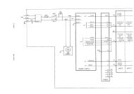
Refer to Figures 3-1, MS<strong>16A</strong> Circuit diagram and 3-2, MS<strong>16A</strong> Printed<br />
circuit board layout.<br />
Logic<br />
The Custom Integrated Circuit IC1 contains a very low power<br />
oscillator, which operates at a fixed frequency. The output of the<br />
master-clock is fed into a divider chain, which includes binary-coded<br />
switches SW4 and SW5, so that rates over a 99:1 range can be<br />
selected.<br />
IC1 also contains the switching electronics which control the Start,<br />
Motor Drive and Guard circuits.<br />
Start<br />
The battery return line (0V) is switched by transistor TR3, which is<br />
controlled from pin 11 of IC1. This control is reset by a negative-going<br />
pulse at IC1, pin 10. Since IC1, pin 10 is biased low through resistor<br />
R2, the negative-going pulse is provided in the transition period<br />
during operation or release of the START/TEST button (SW1).<br />
Diode D1 (a low voltage-drop type) protects the circuit components<br />
from damage if the battery polarity is reversed.<br />
3<br />
Motor drive<br />
In the operation mode, IC1, pin 21 produces a square-wave pulse<br />
train, the frequency of which is determined by the setting of the Set<br />
Rate rotary switches SW4 and SW5. When the output from IC1, pin<br />
21 goes high, transistor TR2 is turned on and TR1 is turned off.<br />
With the cam-operated switch (SW3) in the position shown in Figure<br />
3.1, the motor circuit is completed via TR2, and the motor runs until<br />
the cam operates the switch S3, (1/6 revolution). Because TR1 is<br />
turned off whilst TR2 is conducting, the motor circuit is broken and<br />
the motor stops (perhaps after some overrun). When the output from<br />
IC1, pin 21 goes low, transistor TR2 is turned off and TR1 is turned<br />
on.<br />
The motor circuit is now completed via TR1 and the motor runs until<br />
the cam-operated switch (SW3) returns to its original position<br />
(another 1/6 revolution). Because TR2 is turned off whilst IC1/21<br />
remains low, the motor circuit is once again broken until the next<br />
high output from IC1, pin 21 restarts the sequence.<br />
Since each motor pulse results in 1/6 of a revolution of the leadscrew,<br />
the actuator advances the syringe plunger by 1/6 of the thread pitch,<br />
that is by 0.117 mm.<br />
Technical <strong>Service</strong> <strong>Manual</strong> Issue 6 (February 2005) 3 — 3