GRASEBY Ms 16A Infusion Pump Service Manual - internetMED
GRASEBY Ms 16A Infusion Pump Service Manual - internetMED
GRASEBY Ms 16A Infusion Pump Service Manual - internetMED

Create successful ePaper yourself
Turn your PDF publications into a flip-book with our unique Google optimized e-Paper software.
Smiths Medical Publications<br />
This publication has been compiled and approved by Smiths<br />
Medical for use with their respective products. It is supplied in<br />
this format to permit users to access the text and illustrations<br />
for their own use e.g. training and educational purposes.<br />
Users of the equipment must ensure that they have read and<br />
understood the contents of the complete manual including the<br />
warnings and cautions and have been trained in the correct use<br />
of the product.<br />
Smiths Medical cannot be held responsible for the accuracy and<br />
any resulting incident arising from information that has been<br />
extracted from this publication and compiled into the users<br />
documentation.<br />
This publication maybe subject to revision and it is the users<br />
responsibility to ensure that the correct version of manual/<br />
text/illustration is used in conjunction with the equipment.
Graseby ® MS<strong>16A</strong><br />
Syringe Driver<br />
Technical <strong>Service</strong><br />
<strong>Manual</strong><br />
Part Number 00SM-0105-6<br />
Issue 6 (February 2005)<br />
© 2005 Smiths Medical family of companies. All rights reserved.
Smiths Medical<br />
MS<strong>16A</strong> Syringe Driver<br />
Published by Smiths Medical.<br />
All possible care has been taken in the preparation of this<br />
publication, but Smiths Medical, accepts no liability for any<br />
inaccuracies that may be found.<br />
Smiths Medical reserves the right to make changes without notice<br />
both to this publication and to the product which it describes.<br />
Copyright © 2005 Smiths Medical family of companies. All rights<br />
reserved.<br />
No part of this publication may be reproduced, transmitted,<br />
transcribed, or stored in a retrieval system or translated into any<br />
human or computer language in any form or by any means without<br />
the prior permission of Smiths Medical.<br />
Smiths Medical MD, Inc.<br />
1265 Grey Fox Road, St. Paul, MN 55112, U.S.A.<br />
European Representative:<br />
Smiths Medical International Limited<br />
Watford, Hertfordshire,<br />
United Kingdom, WD24 4LG<br />
http://www.smiths-medical.com<br />
Registered in England. Company number 362847<br />
Trademarks and acknowledgements:<br />
“Graseby” and “Smiths” are trademarks of the Smiths Medical family<br />
of companies.<br />
All other trademarks are acknowledged as the property of their<br />
respective owners.<br />
Technical Ser vice <strong>Manual</strong> Issue 6 (February 2005) Page i
MS<strong>16A</strong> Syringe Driver<br />
Smiths Medical<br />
ISSUE RECORD<br />
Issue<br />
No.<br />
Reason for change<br />
Pages<br />
effected<br />
Date<br />
5 Re-issue<br />
of <strong>Manual</strong><br />
All<br />
May 2000<br />
6<br />
Lockbox and<br />
i.d. change.<br />
US variants added. Corporate<br />
All<br />
February 2005<br />
Page ii Issue 6 (February 2005) Technical <strong>Service</strong> <strong>Manual</strong>
Smiths Medical<br />
MS<strong>16A</strong> Syringe Driver<br />
Scope of this manual<br />
This manual enables service personnel to service and repair the<br />
MS<strong>16A</strong> Syringe Driver. It has been updated to incorporate Lockbox<br />
information and the US variant.<br />
Related manuals<br />
Refer to the following Instruction <strong>Manual</strong> when more detailed<br />
operating information is required. The <strong>Service</strong> <strong>Manual</strong> contains basic<br />
driver operation information only.<br />
• MS<strong>16A</strong> Syringe Driver, MS26 Syringe Driver Instruction<br />
<strong>Manual</strong>, part number 0105-0549-A<br />
Smiths Medical service contacts<br />
In the event of any queries or problems that cannot be resolved by<br />
this manual, please contact the appropriate <strong>Service</strong>/ Repair Centre.<br />
UK address<br />
SMITHS MEDICAL INTERNATIONAL LIMITED<br />
Repair Centre<br />
WATFORD<br />
WD24 4LG<br />
ENGLAND<br />
TEL: (+44) (0) 1923 246434 FAX: (+44) (0) 1923 447773<br />
Web: www.smiths-medical.co.uk<br />
USA service address<br />
MARCAL MEDICAL INC.<br />
1114 BENFIELD BLVD, SUITE H<br />
MILLERSVILLE<br />
MARYLAND<br />
21108-2540<br />
TEL: (410) 987 4001 FAX: (410) 987 4004<br />
Web: www.marcalmedical.com<br />
email: customerservice@marcalmedical.com<br />
Technical Ser vice <strong>Manual</strong> Issue 6 (February 2005) Page iii
MS<strong>16A</strong> Syringe Driver<br />
Smiths Medical<br />
Contents<br />
Chapter 1 - Product Overview<br />
Description ............................................................................................................. 1 - 3<br />
Controls ................................................................................................................. 1 - 4<br />
Operation ............................................................................................................... 1 - 4<br />
Packed set ............................................................................................................. 1 - 5<br />
Accessories and consumables ............................................................................. 1 - 6<br />
Chapter 2 - Specification and Standards<br />
Specification .......................................................................................................... 2 - 3<br />
Type ....................................................................................................................... 2 - 3<br />
<strong>Infusion</strong> time........................................................................................................... 2 - 3<br />
Rate range .............................................................................................................. 2 - 3<br />
Motor operating interval .......................................................................................... 2 - 3<br />
Drive accuracy ....................................................................................................... 2 - 3<br />
Drive force .............................................................................................................. 2 - 3<br />
Actuator movement ................................................................................................ 2 - 3<br />
Actuator stroke ....................................................................................................... 2 - 3<br />
Syringe sizes.......................................................................................................... 2 - 3<br />
Occlusion pressure ................................................................................................. 2 - 3<br />
Controls .................................................................................................................. 2 - 3<br />
Alarm ...................................................................................................................... 2 - 3<br />
Indicator ................................................................................................................. 2 - 4<br />
Battery type ............................................................................................................ 2 - 4<br />
Battery life .............................................................................................................. 2 - 4<br />
Accuracy of delivery ............................................................................................... 2 - 4<br />
Dimensions ............................................................................................................ 2 - 4<br />
Weight .................................................................................................................... 2 - 4<br />
Operating conditions ............................................................................................... 2 - 4<br />
Transport and storage ............................................................................................. 2 - 4<br />
Materials ................................................................................................................ 2 - 4<br />
Standards .............................................................................................................. 2 - 5<br />
Electrical safety...................................................................................................... 2 - 5<br />
EMC ....................................................................................................................... 2 - 5<br />
Biological evaluation ............................................................................................... 2 - 5<br />
Packaging ............................................................................................................... 2 - 5<br />
Medical device directive 93/42/EEC ....................................................................... 2 - 5<br />
Quality system standards used .............................................................................. 2 - 5<br />
Symbols ................................................................................................................. 2 - 5<br />
Disposal ................................................................................................................. 2 - 6<br />
Chapter 3 - Circuit Descriptions<br />
Circuit descriptions ................................................................................................ 3 - 3<br />
Logic ...................................................................................................................... 3 - 3<br />
Start ....................................................................................................................... 3 - 3<br />
Motor drive ............................................................................................................. 3 - 3<br />
Primary guard ......................................................................................................... 3 - 4<br />
Secondary guard .................................................................................................... 3 - 4<br />
Switch-off alarm...................................................................................................... 3 - 4<br />
Test circuit .............................................................................................................. 3 - 5<br />
Safety features ....................................................................................................... 3 - 5<br />
Low battery indication ............................................................................................. 3 - 5<br />
MS<strong>16A</strong> Circuit diagram ........................................................................................... 3 - 6<br />
MS<strong>16A</strong> Printed circuit board layout......................................................................... 3 - 7<br />
Page iv Issue 6 (February 2005) Technical <strong>Service</strong> <strong>Manual</strong>
Smiths Medical<br />
MS<strong>16A</strong> Syringe Driver<br />
Chapter 4 - Disassembly and Assembly<br />
General .................................................................................................................. 4 - 3<br />
Tools, equipment and materials required ................................................................ 4 - 3<br />
Removal and dismantling procedures.................................................................... 4 - 5<br />
Case separation...................................................................................................... 4 - 5<br />
Leadscrew and bearing assembly removal .............................................................. 4 - 5<br />
Actuator and back bearing disassembly ................................................................. 4 - 5<br />
PCB removal .......................................................................................................... 4 - 5<br />
Motor and gearbox disassembly ............................................................................. 4 - 6<br />
Assembly procedures ............................................................................................ 4 - 7<br />
Motor and gearbox assembly .................................................................................. 4 - 7<br />
PCB assembly ....................................................................................................... 4 - 7<br />
Actuator and bearing............................................................................................... 4 - 9<br />
Leadscrew and bearing assembly ........................................................................... 4 - 9<br />
Case assembly ...................................................................................................... 4 - 10<br />
Lockbox ............................................................................................................... 4 - 12<br />
Chapter 5 - <strong>Service</strong> Test Procedures<br />
<strong>Service</strong> Test Procedures........................................................................................ 5 - 3<br />
Tools and equipment ............................................................................................... 5 - 3<br />
Adjustments potentiometers ................................................................................... 5 - 4<br />
<strong>Service</strong> Testing....................................................................................................... 5 - 5<br />
Cam follower adjustment ........................................................................................ 5 - 5<br />
9 Volt thrust test ..................................................................................................... 5 - 7<br />
7 Volt thrust test ..................................................................................................... 5 - 7<br />
Guard test .............................................................................................................. 5 - 8<br />
Flash frequency ...................................................................................................... 5 - 8<br />
Timer and feed rate tests ........................................................................................ 5 - 8<br />
Cam alignment ....................................................................................................... 5 - 9<br />
Half nut slip ............................................................................................................ 5 - 9<br />
Rate switch test...................................................................................................... 5 - 9<br />
Current tests ........................................................................................................... 5 - 9<br />
Sounder check ...................................................................................................... 5 - 10<br />
General .................................................................................................................. 5 - 10<br />
Test Checklist - MS<strong>16A</strong> ........................................................................................ 5 - 11<br />
Chapter 6 - Maintenance<br />
Maintenance.......................................................................................................... 6 - 3<br />
Cleaning ................................................................................................................ 6 - 3<br />
Annual performance check ................................................................................... 6 - 3<br />
Battery replacement .............................................................................................. 6 - 4<br />
Continuous alarm conversion ............................................................................... 6 - 5<br />
Basic troubleshooting ........................................................................................... 6 - 6<br />
Chapter 7 - Parts List<br />
General assembly of the MS<strong>16A</strong> ........................................................................... 7 - 3<br />
MS<strong>16A</strong> PCB assembly .......................................................................................... 7 - 7<br />
Technical Ser vice <strong>Manual</strong> Issue 6 (February 2005) Page v
MS<strong>16A</strong> Syringe Driver<br />
Smiths Medical<br />
Figures<br />
1 - 1 MS<strong>16A</strong> Hourly rate syringe driver .................................................................. 1 - 3<br />
1 - 2 Lockbox ......................................................................................................... 1 - 3<br />
1 - 3 MS<strong>16A</strong> Controls ............................................................................................ 1 - 4<br />
1 - 4 Package contents .......................................................................................... 1 - 5<br />
3 - 1 MS<strong>16A</strong> Circuit diagram .................................................................................. 3 - 6<br />
3 - 2 MS<strong>16A</strong> Printed circuit board layout ................................................................ 3 - 7<br />
4 - 1 MS<strong>16A</strong> exploded view ................................................................................... 4 - 4<br />
4 - 2 Release piezo-transducer assembly .............................................................. 4 - 6<br />
4 - 3 Orientation of dials and rate switches ............................................................ 4 - 7<br />
4 - 4 Foam pad position ......................................................................................... 4 - 8<br />
4 - 5 Piezo-transducer wiring.................................................................................. 4 - 9<br />
4 - 6 Sealant application ....................................................................................... 4 - 10<br />
4 - 7 Lockbox ........................................................................................................ 4 - 12<br />
5 - 1 Cam and cam follower ................................................................................... 5 - 5<br />
5 - 2 Camswitch operating timing ........................................................................... 5 - 5<br />
5 - 3 Typical waveform for one pulse ...................................................................... 5 - 6<br />
5 - 4 Using the cam adjustment tool ...................................................................... 5 - 7<br />
5 - 5 Thrust rig set-up............................................................................................. 5 - 7<br />
6 - 1 Battery replacement ...................................................................................... 6 - 4<br />
6 - 2 Continuous alarm conversion ......................................................................... 6 - 5<br />
7 - 1 Exploded view of the MS<strong>16A</strong> Syringe Driver .................................................. 7 - 4<br />
7 - 2 MS<strong>16A</strong> PCB assembly .................................................................................. 7 - 7<br />
Page vi Issue 6 (February 2005) Technical <strong>Service</strong> <strong>Manual</strong>
Smiths Medical<br />
MS<strong>16A</strong> Syringe Driver<br />
Warnings<br />
Warnings tell you about dangerous conditions that may occur, and<br />
which could lead to death or serious injury to the user or patient if<br />
you do not obey all of the instructions in this manual.<br />
1. Remember the rate is set in milliMETRES NOT milliLITRES. The correct rate is essential to<br />
prevent serious injury or death to the patient.<br />
2. Any damaged pumps must be thoroughly tested by a competent person in accordance with the<br />
procedures in this service manual before re-use with a patient. Failure to observe this may result<br />
in patient injury or death.<br />
2. Completely prime the administration set, and remove all air from both the administration set and<br />
the syringe before measuring the mm of fluid length, otherwise the rate calculation will be<br />
incorrect.<br />
3. The driver must only be used with the syringe rubber securing strap fixed firmly in place, thus<br />
preventing an uncontrolled infusion to the patient that could result in serious injury or death.<br />
4. Never take a syringe that is not empty off the driver if it is still connected to the patient.<br />
The infusion line must first be clamped or disconnected to prevent serious injury or death to the<br />
patient.<br />
5. The use of spare parts other than those recommended is not advised, and may affect the correct<br />
operation of the driver, resulting in injury or death.<br />
6. The syringe driver must not be used for infusing medication where pulsatile delivery action is<br />
unacceptable.<br />
7. The syringe driver must not be used in environments with flammable gas mixtures or with oxygenenriched<br />
atmospheres.<br />
8. If the syringe driver is used in the lockbox, the alarm volume will be reduced.<br />
Technical Ser vice <strong>Manual</strong> Issue 6 (February 2005) Page vii
MS<strong>16A</strong> Syringe Driver<br />
Smiths Medical<br />
Cautions<br />
Cautions tell you about dangerous conditions that can occur which<br />
may cause damage to the pump if you do not obey all of the<br />
instructions in this manual.<br />
A damaged pump must never be put into active service, as it<br />
may be a hazard to patients through under- or over-infusing.<br />
1. To prevent serious damage to the driver it must not be immersed in any liquids or exposed to<br />
strong organic solvents. If immersion occurs or the driver is subject to a serious spillage or<br />
wetting incident, it must be thoroughly tested by a competent person in accordance with the<br />
procedures in this service manual before re-use with a patient.<br />
2. Wipe off spills immediately. Do not allow fluid or residues to remain on the pump.<br />
3. The pump is not designed to be autoclaved, steam-sterilised, ETO sterilised or subjected to<br />
temperatures in excess of 45° C (113° F). Failure to observe this caution may cause serious damage<br />
to the pump.<br />
4. To avoid possible malfunction of the pump, do not expose the pump to X- rays, gamma rays or<br />
other ionizing radiation, or to the RF interference or strong electric / magnetic fields emitted (for<br />
example) by arc welding equipment or mobile transmitting equipment.<br />
5. Moving parts of the driver do not require lubrication during their lifetime. Worn or stiff parts<br />
should be replaced.<br />
6. Handling the printed circuit board is required during disassembly/ assembly. A static controlled<br />
work station including a conductive mat and grounded wrist strap should be used to provide<br />
protection against electrostatic discharge (ESD) or circuit board damage could result.<br />
Take care to avoid contamination of the exposed switches, circuit tracks and components, e.g. by<br />
the entry of solder particles.<br />
7. Refer all service, repair, testing and calibrations to suitably qualified technical personnel.<br />
Unauthorised modifications to the driver must not be carried out.<br />
8. Federal law restricts these Syringe Drivers for use by or on the order of a physician. This applies to<br />
drivers distributed only within the United States.<br />
Page viii Issue 6 (February 2005) Technical <strong>Service</strong> <strong>Manual</strong>
Smiths Medical<br />
MS<strong>16A</strong> Syringe Driver<br />
Glossary<br />
Abbreviations<br />
The following abbreviations are used in this <strong>Manual</strong>.<br />
Abbreviation<br />
ABS<br />
C<br />
cNm<br />
DC<br />
gm<br />
h/hr<br />
hPa<br />
IC<br />
Kg<br />
Kgf<br />
KHz<br />
LED<br />
ml<br />
mm<br />
N<br />
PCB<br />
R<br />
RH<br />
Sec<br />
SW<br />
TR<br />
V<br />
Meaning<br />
Acrylonitrile Butadiene Styrene<br />
Centigrade or capacitor<br />
Centinewton metre<br />
Direct Current<br />
grams<br />
hour<br />
Hectopascal (=100 pascals)<br />
Integrated Circuit<br />
Kilogram<br />
Kilogram force<br />
Kilohertz<br />
Light Emitting Diode<br />
Millilitre<br />
Millimetre<br />
Newton<br />
Printed Circuit Board<br />
Resistor<br />
Relative Humidity<br />
Second<br />
Switch<br />
Transistor<br />
Volts<br />
Technical Ser vice <strong>Manual</strong> Issue 6 (February 2005) Page ix
MS<strong>16A</strong> Syringe Driver<br />
Smiths Medical<br />
Page x Issue 6 (February 2005) Technical <strong>Service</strong> <strong>Manual</strong>
Graseby ® MS<strong>16A</strong><br />
Syringe Driver<br />
1<br />
Chapter 1<br />
Product Overview
Smiths Medical<br />
MS<strong>16A</strong> Syringe Driver<br />
Chapter 1 - Product Overview<br />
1<br />
Description<br />
Figure 1-1 MS<strong>16A</strong> Hourly rate syringe driver<br />
The MS<strong>16A</strong> Syringe Driver (Figure 1-1) is a portable, batteryoperated<br />
device, designed for the continuous infusion of small<br />
volumes of liquid from commercially available disposable syringes.<br />
The driver operates over time spans ranging from less than 30<br />
minutes to 60 hours.<br />
The syringe plunger is operated by a linear actuator, at rates ranging<br />
from 1 to 99 mm/hour (mm PER). The rate required is set by<br />
adjusting two digital rotary switches.<br />
Most brands of syringe can be fitted to the driver, and the volumetric<br />
delivery depends on the size of the syringe being used. A millimetre<br />
scale is provided on the front of the driver to measure the stroke<br />
length of the syringe, so that the rate in mm/hour may be calculated.<br />
For added security, the syringe driver can be secured in a<br />
transparent plastic, lockable box (see Figure 1-2).<br />
When fitted, the box minimises the risk of tampering with the<br />
infusion.<br />
Figure 1-2 Lockbox<br />
Technical <strong>Service</strong> <strong>Manual</strong> Issue 6 (February 2005)<br />
1 — 3
MS<strong>16A</strong> Syringe Driver<br />
Smiths Medical<br />
The clear plastic lockbox is hinged at the back and features a lock at<br />
the front. The syringe is held in place on the driver by the securing<br />
strap and the infusion line passed through the slot at the front of the<br />
box. When the mm PER setting has been selected and the START/<br />
TEST pushbutton pressed, the loaded driver is located in the box<br />
which is then locked. The patient controls (Figure 1-3) may be viewed<br />
through the clear window at the side of the lockbox.<br />
1<br />
Controls<br />
Patient controls (Figure 1-3) consist of two rotary set rate mm PER<br />
slotted switches, and a START/TEST pushbutton.<br />
START/TEST<br />
50 60mm<br />
GM0418-A<br />
GM0307-A<br />
0<br />
9<br />
mm PER<br />
Figure 1-3 MS<strong>16A</strong> Controls<br />
Operation<br />
Note: For detailed operating information, refer to the MS<strong>16A</strong>, MS26<br />
Instruction <strong>Manual</strong>, part number 0105-0549.<br />
To start an infusion, fit a primed syringe and press the START/TEST<br />
pushbutton.<br />
When held down, the START/TEST pushbutton tests a safety cut-out<br />
circuit. When released, it starts the drive circuit. Once started, the<br />
front panel LED flashes approximately every second.<br />
When the plunger reaches the end of travel (syringe empty) or is<br />
occluded, the driver switches off, the LED stops flashing and an<br />
audible alarm sounds.<br />
If the START/TEST pushbutton is held down for more than 3 seconds,<br />
the alarm sounds, the driver stops and the LED stops flashing.<br />
If required, the driver can be modified to sound a continuous tone<br />
when the driver stops. See Chapter 6, Maintenance for modification<br />
instructions.<br />
For additional protection, the syringe driver can be secured in a<br />
Lockbox.<br />
1 — 4<br />
Issue 6 (February 2005)<br />
Technical <strong>Service</strong> <strong>Manual</strong>
Smiths Medical<br />
MS<strong>16A</strong> Syringe Driver<br />
Packed set<br />
The MS<strong>16A</strong> packed set (part number 0105-0504) is supplied with the<br />
following items:-<br />
1. MS<strong>16A</strong> Syringe Driver.<br />
2. Battery, type IEC 6LR61.<br />
3. Instruction manual.<br />
4. Rate adjuster.<br />
5. Shoulder holster (not US version).<br />
1<br />
6. Clear cover (not shown).<br />
Figure 1-4 Package contents<br />
Technical <strong>Service</strong> <strong>Manual</strong> Issue 6 (February 2005)<br />
1 — 5
MS<strong>16A</strong> Syringe Driver<br />
Smiths Medical<br />
Accessories and consumables<br />
Item Description Part number<br />
100 cm infusion set PVC line with 25 gauge needle. 0105-0029<br />
Subcutaneous BD 10 ml syringe, Tegaderm dressing 0105-0117<br />
infusion pack alcohol wipe, transfer needle,<br />
100 cm infusion set.<br />
1<br />
Syringe driver Provides a secure base to stand the 0105-0108<br />
non-slip base syringe drive on a flat surface.<br />
Cover Clear rigid plastic to protect the syringe 0105-0529<br />
driver and syringe.<br />
Holster Washable, soft fabric holster with cover 0105-0027<br />
Instruction manual Instructions for use. Guide to subcutaneous 0105-0549<br />
analgesia, technical and performance<br />
specifications.<br />
Rate adjuster Tool to turn slotted rate switches. 0105-0023<br />
Training pack A full package of presentation, instruction TPF-00130<br />
and testing materials.<br />
Lockbox A transparent plastic, lockable security 0105-0640<br />
container (includes two keys). See page 1-3.<br />
1 — 6<br />
Issue 6 (February 2005)<br />
Technical <strong>Service</strong> <strong>Manual</strong>
Graseby ® MS<strong>16A</strong><br />
Syringe Driver<br />
2<br />
Chapter 2<br />
Specification and Standards
Smiths Medical<br />
MS<strong>16A</strong> Syringe Driver<br />
Chapter 2 - Specification and Standards<br />
Type:<br />
Syringe driver with motor driven linear actuator, pulsed motion. Internal 9 V<br />
alkaline battery power source. Digital electronic rate control.<br />
Automatic switch off when the syringe is empty.<br />
<strong>Infusion</strong> time:<br />
< 30 min. - 60 hours<br />
Rate range:<br />
Variable delivery rate of 0 - 99 mm/h in steps of 1 mm/h.<br />
Motor operating interval:<br />
420 ÷ rate = seconds<br />
2<br />
Drive accuracy:<br />
The accuracy of the linear drive mechanism that pushes the syringe plunger<br />
forward: ± 5%<br />
Drive force:<br />
The force the linear drive mechanism that pushes the syringe plunger forward can<br />
produce: >3 Kg<br />
Actuator movement:<br />
0.12 mm every time motor turns.<br />
Actuator stroke:<br />
60 mm available (depends on syringe).<br />
Syringe sizes:<br />
2 ml to 35 ml<br />
The holster supplied will enclose most types of syringe up to 20 ml capacity.<br />
Occlusion pressure:<br />
3 - 5 Kg<br />
Maximum actuator force 50 N (5 Kgf) @ 9 V<br />
Controls:<br />
START/TEST and mm PER rate adjusters (tens and units digit controls).<br />
Alarm:<br />
Audible frequency:<br />
Duration:<br />
Volume:<br />
3 kHz ± 0.5 kHz (end of travel: occlusion).<br />
5 - 20 secs.<br />
Audible at 1m with normal or corrected hearing<br />
Technical <strong>Service</strong> <strong>Manual</strong> Issue 6 (February 2005) 2 — 3
MS<strong>16A</strong> Syringe Driver<br />
Smiths Medical<br />
Indicator:<br />
Low battery level: 7.0 V to 5.5 V (LED stops flashing)<br />
Flash period: 1.05 secs ± 2%<br />
Yellow solid state LED<br />
Green solid state LED (US)<br />
Battery type:<br />
PP3 size. 9 V, primary alkaline, IEC 6LR61 (or 6LF22) type.<br />
(Duracell MN1604 recommended)<br />
2<br />
Battery life:<br />
50 full deliveries depending on the operating conditions and battery condition.<br />
Automatic switch off at end of plunger travel.<br />
Accuracy of delivery:<br />
The rate of the actuator is accurate to within plus or minus 5% of the rate set on<br />
the rotary switches.<br />
Dimensions (without syringe):<br />
Height: 53.0 ± 0.5 mm<br />
Width: 166.0 ± 1.0 mm<br />
Depth: 23.0 ± 1.0 mm<br />
Weight (including battery):<br />
190 gm.<br />
Operating conditions:<br />
+10° C to +40° C. 30% to 75% RH (non-condensing).<br />
700 hPa to 1060 hPa<br />
Transport and storage conditions:<br />
-40° C to +70° C. 10% to 100% RH (non-condensing).<br />
500 hPa to 1060 hPa<br />
Materials:<br />
Case and battery cover - ABS RTA 50 injection moulding.<br />
Labels - 125 micron fine matt Lexan.<br />
Other materials - nitrile rubber, small plastic parts - Acetal (25% glass filled<br />
Kemetal) and PA-GF (glass-filled nylon).<br />
Metal parts - stainless steel, mild steel.<br />
Circuit board - epoxy glass fabric.<br />
Holster - elasticated soft-backed fabric.<br />
Note: All materials used in this product are latex free.<br />
2 — 4<br />
Issue 6 (February 2005)<br />
Technical <strong>Service</strong> <strong>Manual</strong>
Smiths Medical<br />
MS<strong>16A</strong> Syringe Driver<br />
Standards<br />
Electrical safety:<br />
Complies with EN 60601-1: 1990 (IEC 601-1:1988).<br />
Type BF Applied Part for protection against electric shock.<br />
EMC:<br />
Complies with EN 60601-1-2:1993 for emissions and immunity to electromagnetic<br />
disturbances. Group 1 Class B for emitted RF radiation according to EN 55011:1991<br />
making it acceptable for use in domestic establishments.<br />
Complies with RTCA DO-160D (Operation in a commercial aircraft with controlled<br />
pressurised cabin area which maintains cabin pressure at normal cabin<br />
environment.) Smiths Medical International Ltd. ref. CIB B1100.<br />
Biological evaluation:<br />
Complies with EN 30993-1:1994 Biological evaluation of medical devices - Part 1:<br />
Guidance on selection of tests.<br />
2<br />
Packaging:<br />
Complies with EN 20780:1993 Packaging - Pictorial marking for handling of goods.<br />
Medical device directive 93/42/EEC:<br />
CE marked under Annex II, risk class IIb (active medical device).<br />
Notified Body: AMTAC (0473).<br />
Quality system standards used:<br />
EN ISO 9001 and EN 46001.<br />
Symbols<br />
An electrical safety classification in the international safety standard for medical<br />
electrical equipment, Type BF. If the equipment is used as intended there is no risk<br />
of a serious electric shock. But it is not suitable for direct connection to the heart.<br />
Refer to the accompanying instructions on how to use the equipment.<br />
Detailed instructions on how to use the syringe driver are given in the Instruction<br />
<strong>Manual</strong>, part number 0105-0549.<br />
The CE mark demonstrates that the Syringe Driver conforms to the requirements in<br />
the European Council Directive 93/42/EEC concerning medical devices.<br />
The number 0473 identifies the Notified Body under which the Quality Systems<br />
operated within Smiths Medical are assessed.<br />
Technical <strong>Service</strong> <strong>Manual</strong> Issue 6 (February 2005) 2 — 5
MS<strong>16A</strong> Syringe Driver<br />
Smiths Medical<br />
Disposal<br />
When disposing of the driver or its accessories do so in the best way to minimise any<br />
negative impact on the environment.<br />
The internal battery contains harmful substances. First discharge the battery. Do not<br />
open up the battery, or incinerate it as it could explode.<br />
Contact your local waste disposal service to find out about special recycling or<br />
disposal schemes.<br />
2<br />
Separate any other parts of the driver where arrangements can be made for their<br />
recovery, either by recycling or energy recovery.<br />
Important:<br />
Existing national or local regulations concerning waste disposal must take<br />
precedence over this advice.<br />
2 — 6<br />
Issue 6 (February 2005)<br />
Technical <strong>Service</strong> <strong>Manual</strong>
Graseby ® MS<strong>16A</strong><br />
Syringe Driver<br />
3<br />
Chapter 3<br />
Circuit Descriptions
Smiths Medical<br />
MS<strong>16A</strong> Syringe Driver<br />
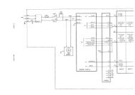
Chapter 3 - Circuit Descriptions<br />
Refer to Figures 3-1, MS<strong>16A</strong> Circuit diagram and 3-2, MS<strong>16A</strong> Printed<br />
circuit board layout.<br />
Logic<br />
The Custom Integrated Circuit IC1 contains a very low power<br />
oscillator, which operates at a fixed frequency. The output of the<br />
master-clock is fed into a divider chain, which includes binary-coded<br />
switches SW4 and SW5, so that rates over a 99:1 range can be<br />
selected.<br />
IC1 also contains the switching electronics which control the Start,<br />
Motor Drive and Guard circuits.<br />
Start<br />
The battery return line (0V) is switched by transistor TR3, which is<br />
controlled from pin 11 of IC1. This control is reset by a negative-going<br />
pulse at IC1, pin 10. Since IC1, pin 10 is biased low through resistor<br />
R2, the negative-going pulse is provided in the transition period<br />
during operation or release of the START/TEST button (SW1).<br />
Diode D1 (a low voltage-drop type) protects the circuit components<br />
from damage if the battery polarity is reversed.<br />
3<br />
Motor drive<br />
In the operation mode, IC1, pin 21 produces a square-wave pulse<br />
train, the frequency of which is determined by the setting of the Set<br />
Rate rotary switches SW4 and SW5. When the output from IC1, pin<br />
21 goes high, transistor TR2 is turned on and TR1 is turned off.<br />
With the cam-operated switch (SW3) in the position shown in Figure<br />
3.1, the motor circuit is completed via TR2, and the motor runs until<br />
the cam operates the switch S3, (1/6 revolution). Because TR1 is<br />
turned off whilst TR2 is conducting, the motor circuit is broken and<br />
the motor stops (perhaps after some overrun). When the output from<br />
IC1, pin 21 goes low, transistor TR2 is turned off and TR1 is turned<br />
on.<br />
The motor circuit is now completed via TR1 and the motor runs until<br />
the cam-operated switch (SW3) returns to its original position<br />
(another 1/6 revolution). Because TR2 is turned off whilst IC1/21<br />
remains low, the motor circuit is once again broken until the next<br />
high output from IC1, pin 21 restarts the sequence.<br />
Since each motor pulse results in 1/6 of a revolution of the leadscrew,<br />
the actuator advances the syringe plunger by 1/6 of the thread pitch,<br />
that is by 0.117 mm.<br />
Technical <strong>Service</strong> <strong>Manual</strong> Issue 6 (February 2005) 3 — 3
MS<strong>16A</strong> Syringe Driver<br />
Smiths Medical<br />
Note:<br />
The amount of overrun at each step, though indeterminate, is<br />
non-cumulative. After 60 pulses the cam will have rotated<br />
through ten revolutions plus the error of the last step.<br />
Transistor TR4 and its associated components form an adjustable<br />
current regulator which is pre-set to limit the torque of the motor<br />
and therefore the maximum actuator thrust. Because the motor drive<br />
pulses may be quite infrequent, a light emitting diode (LED) is driven<br />
at a fixed frequency by IC1, pin 14. This provides a continuous check<br />
on the functioning of the oscillator and the low battery indication (see<br />
Low battery indication, page 3 - 5).<br />
3<br />
Primary guard<br />
Whenever the motor is energised (i.e. whenever the node marked A<br />
is held low), this is sensed at IC1, pin 22. If A is held low for more<br />
than 3.7 seconds (896 cycles of the master-clock). the output from IC1,<br />
pin 11 causes TR3 to switch off.<br />
In normal use, the motor runs for less than 3.7 seconds, so the guard<br />
circuit only operates when the motor is stalled (e.g. when the syringe<br />
is empty or when the delivery line is occluded), if a transistor or the<br />
cam-operated switch fails, or when the START/TEST pushbutton is<br />
held depressed.<br />
Secondary guard<br />
Switch-off alarm<br />
If the main oscillator ever fails, the run time of the motor is limited<br />
by a secondary guard circuit.<br />
When the motor is energised, capacitor C2 acquires a charge via<br />
resistor R4 (the charge is quickly dissipated at the end of the motor<br />
drive pulse by diode D4).<br />
If the motor attempts to run for longer than approximately 5 seconds,<br />
the voltage on capacitor C2 (i.e. voltage at IC1, pin 9) falls to a critical<br />
level, causing the output from IC1, pin 11 to switch off TR3.<br />
The driver will fail safe (switch off), regardless of how A came to be<br />
held low for longer than the normal operating pulse duration.<br />
The piezo-transducer (X1) and associated components (TR8, R18, R15,<br />
R16) are arranged so that an alarm tone sounds when the bottom end<br />
of R16 is held low. This occurs for a few seconds whenever TR3<br />
switches off, owing to TR9 being turned on until C5 is charged via<br />
R17.<br />
3 — 4<br />
Issue 6 (February 2005)<br />
Technical <strong>Service</strong> <strong>Manual</strong>
Smiths Medical<br />
MS<strong>16A</strong> Syringe Driver<br />
Test circuit<br />
Safety features<br />
When the START/TEST button is pressed and held, TR3 is turned on<br />
by switch S1 (see Start, page 3 - 1) and the motor circuit completed<br />
via switch S2. The motor runs until it is switched off by the primary<br />
guard circuit. When the button is released, the syringe driver<br />
resumes the normal drive mode.<br />
Part of the circuit associated with pins 9, 10, 11 and 12 operates, via<br />
TR3, to allow the operation of the driver only while safe conditions<br />
exist. A crucial design feature of IC1 is that this area of circuitry is<br />
completely separated within the silicon chip by a diffusion well and<br />
has a separate power supply (VSS’).<br />
Protection against overdosing is provided by three basic concepts:<br />
1. Breaking the motor current by the cam-operated microswitch.<br />
2. The complementary, master-slave action of transistors TR1 and<br />
TR2.<br />
3<br />
3. The Guard circuit, with two methods of activation.<br />
Low battery indication<br />
The master-clock in IC1 causes pin 14 to be grounded approximately<br />
once per second. During this pulse, transistor TR5 conducts. This<br />
illuminates the LED, providing the battery voltage is sufficient to<br />
cause about 0.6 volts to be developed across resistor R13.<br />
When the battery voltage is too low to switch on transistor TR5, the<br />
LED ceases to flash.<br />
Technical <strong>Service</strong> <strong>Manual</strong> Issue 6 (February 2005) 3 — 5
MS<strong>16A</strong> Syringe Driver<br />
Smiths Medical<br />
3<br />
SW1<br />
GM1193-D<br />
1<br />
F<br />
SW3<br />
SW2<br />
A<br />
Figure 3-1<br />
MS<strong>16A</strong> Circuit diagram<br />
3 — 6<br />
Issue 6 (February 2005)<br />
Technical <strong>Service</strong> <strong>Manual</strong>
Smiths Medical<br />
MS<strong>16A</strong> Syringe Driver<br />
3<br />
Figure 3-2 MS<strong>16A</strong> Printed circuit board layout<br />
Technical <strong>Service</strong> <strong>Manual</strong> Issue 6 (February 2005) 3 — 7
Graseby ® MS<strong>16A</strong><br />
Syringe Driver<br />
Chapter 4<br />
4<br />
Disassembly and Assaembly
Smiths Medical<br />
MS<strong>16A</strong> Syringe Driver<br />
Chapter 4 - Disassembly and Assembly<br />
General<br />
Warnings:<br />
Refer all service, repair, testing and calibrations only to suitably<br />
qualified technical personnel. Unauthorised modifications to the<br />
driver must not be carried out.<br />
The use of spare parts other than those recommended is not advised,<br />
and may affect the correct operation of the driver, resulting in injury or<br />
death.<br />
Cautions:<br />
The moving parts of the driver do not require any lubrication during<br />
their lifetime. Any worn or stiff parts should be replaced.<br />
With the case dismantled take great care to avoid contamination of the<br />
exposed switches, e.g. by the entry of solder particles.<br />
Handling of printed circuit boards is required during disassembly/<br />
assembly. A static controlled work station including a conductive mat<br />
and grounded wrist strap should be used to provide protection<br />
against electrostatic discharge (ESD) or circuit board damage could<br />
result.<br />
4<br />
The following procedures describe the dismantling and assembly<br />
sequence when replacing parts.<br />
If the case halves are separated, the complete test routine (see<br />
Chapter 5, Testing) must be completed successfully.<br />
Unless otherwise stated, tighten screws to a torque of 30 - 35 cNm.<br />
A faulty PCB should be replaced with a new PCB.<br />
The item numbers given in the following descriptions refer to Figure<br />
4-1, MS<strong>16A</strong> exploded view.<br />
Tools, equipment and materials required<br />
Cam adjustment tool Part number 0105-0079<br />
Silicone grease Part number 6835-2006<br />
Silicone sealant, non-acetic Loctite 209161, or similar.<br />
For a list of additional tools and materials used when testing the<br />
MS<strong>16A</strong>, see Chapter 5, Testing, page 5-1.<br />
Technical <strong>Service</strong> <strong>Manual</strong> Issue 6 (February 2005) 4 — 3
3<br />
3<br />
0<br />
MS<strong>16A</strong> Syringe Driver<br />
Smiths Medical<br />
4<br />
01 2<br />
8 9<br />
3<br />
7<br />
23<br />
4 5 6<br />
4<br />
5 6 7 8 9<br />
7<br />
8<br />
6<br />
5<br />
4<br />
3<br />
9<br />
01 2<br />
9<br />
2<br />
1<br />
4<br />
7<br />
GM1198-B<br />
3<br />
4<br />
20<br />
8<br />
19<br />
17<br />
5<br />
6<br />
7<br />
10<br />
11<br />
10<br />
12<br />
9<br />
18<br />
21<br />
16<br />
27<br />
15<br />
1<br />
2<br />
14<br />
26<br />
13<br />
22<br />
24<br />
25<br />
28<br />
29<br />
Figure 4-1 MS<strong>16A</strong> exploded view<br />
4 — 4<br />
Issue 6 (February 2005)<br />
Technical <strong>Service</strong> <strong>Manual</strong>
Smiths Medical<br />
MS<strong>16A</strong> Syringe Driver<br />
Removal and dismantling procedures<br />
1. Case separation<br />
a. Lay the driver face down on a clean flat surface.<br />
b. Slide off the battery cover (item 27) and if fitted, remove the<br />
battery.<br />
c. Remove the three screws and washer securing the halves of the<br />
case assembly. Lift off the rear half.<br />
d. If the case is sealed, gently pry the two halves apart. Remove any<br />
sealant from mating surfaces.<br />
2. Leadscrew and bearing assembly removal<br />
a. Separate the case halves as above.<br />
b. Loosen the motor clamp (item 13) so that the motor and gearbox<br />
assembly (item 14) can be tilted clear of the case.<br />
c. Gently pull the leadscrew and actuator assembly (items 15 and<br />
16) from the motor and gearbox assembly.<br />
3. Actuator and back bearing disassembly<br />
a. Separate the case halves and remove the leadscrew and bearing<br />
assembly as above.<br />
4<br />
4. PCB removal<br />
b. Remove the back bearing (item 20) from the end of the leadscrew.<br />
c. Depress the plunger (half nut - item 18) on the actuator assembly<br />
(item 19) and slide the actuator off the leadscrew at the back<br />
bearing end.<br />
When the half nut and spring are freed from the leadscrew,<br />
ensure that they are not mislaid. Ensure that the half nut is bluerimmed.<br />
a. Separate the case halves and remove the leadscrew and bearing<br />
assembly as above.<br />
b. Remove the motor clamp (item 13), screw and fibre washer.<br />
c. Remove the four remaining screws and fibre washers securing<br />
the PCB assembly (item 22) to the front case (item 2).<br />
If the wires for the piezo-transducer assembly (item 25) are<br />
secured with an adhesive pad to the motor clamp (item 13),<br />
carefully lift the leads from the pad.<br />
d. Pull the battery connector springs from their locating slots and<br />
lift out the PCB assembly and motor and gearbox assembly.<br />
Technical <strong>Service</strong> <strong>Manual</strong> Issue 6 (February 2005) 4 — 5
MS<strong>16A</strong> Syringe Driver<br />
Smiths Medical<br />
The START/TEST pushbutton, seal and switchplate (items 5, 6<br />
and 7) may remain in the case.<br />
e. To release the piezo-transducer (see Figure 4-2) assembly, unplug<br />
IC1 from its socket, exposing the fixing clip. Remove the piece of<br />
rubber from the clip. Do not pull on the metal disk. Push the clip<br />
through, whilst gently holding the transducer assembly.<br />
4<br />
Figure 4-2 Release piezo-transducer assembly<br />
f. To remove the PCB assembly completely, unsolder the motor<br />
gearbox assembly (item 14) from the PCB.<br />
g. Ensure that all traces of sealant (if applied) are removed from<br />
mating surfaces.<br />
5. Motor and gearbox disassembly<br />
a. Separate the case halves and remove the leadscrew and bearing<br />
assembly as described in paragraphs 1, 2 and 3 above.<br />
b. Remove the PCB assembly (see paragraph 4, a - d above).<br />
c. Unsolder the motor and gearbox assembly (item 13) from the<br />
PCB.<br />
4 — 6<br />
Issue 6 (February 2005)<br />
Technical <strong>Service</strong> <strong>Manual</strong>
Smiths Medical<br />
MS<strong>16A</strong> Syringe Driver<br />
Assembly procedures<br />
Note: Unless otherwise stated, tighten all screws to a torque of<br />
30 - 35 cNm.<br />
1. Motor and gearbox assembly<br />
2. PCB assembly<br />
a. If a replacement motor is being fitted, align the pin in the cam<br />
assembly with the slot in the gearbox shaft and press the cam<br />
assembly onto the shaft.<br />
b. Connect and solder the motor leads to the PCB: red to M+ and<br />
black to M-.<br />
c. Refit the PCB assembly, complete with the motor and gearbox, and<br />
the leadscrew assembly.<br />
Ensure that the transducer is correctly wired to the PCB: blue to TP1,<br />
red to TP2, black to TP3.<br />
When reassembled, ensure that the three pegs on the transducer base<br />
are located in the holes in the PCB.<br />
a. Fit the two rate dials (items 11 and 12), on the rate switches SW4<br />
and SW5 (items 26). A rubber seal (item 10) must be fitted firmly<br />
into the groove, in each of the dials.<br />
4<br />
i. Place the two dials face-upwards on the bench, side by side,<br />
so that the numbers on each dial, on the adjacent sides, are the<br />
correct way up (if upside down, change the dials left to right).<br />
ii.<br />
Keeping the dials in the same relative position insert the<br />
left-hand dial in SW4 and the right-hand dial in SW5, ensuring<br />
that the dial position and switch position correspond<br />
(see Figure 4-3).<br />
Figure 4-3 Orientation of dials and rate switches<br />
Technical <strong>Service</strong> <strong>Manual</strong> Issue 6 (February 2005) 4 — 7
MS<strong>16A</strong> Syringe Driver<br />
Smiths Medical<br />
iii. Apply a smear of silicone grease (Smiths Medical<br />
part number 6835-2006) to the edge of the slotted head screw<br />
(items 11 and 12).<br />
b. Assemble the START/TEST pushbutton, seal and switch bar<br />
(items 5, 6 and 7) and place them in position over microswitches<br />
SW1 and SW2.<br />
Ensure that the switch bar is aligned across the contacts of SW1<br />
and SW2.<br />
Ensure that the cam lever (part of item 15) is on SW3 and that it<br />
pivots freely.<br />
c. Ensure that the foam pad is fitted to the inside of the front case<br />
(see Figure 4-4, Foam pad position). Place the front case half<br />
(item 1) over the PCB and hold it in position. Turn the PCB and<br />
case over so that the PCB is uppermost. Check that the leads for<br />
the motor and battery connector springs are not trapped.<br />
Figure 4-4 Foam pad position<br />
4<br />
d. Push the battery connector springs into their slots. Red to + and<br />
Black to - ve, as shown on the battery compartment label.<br />
e. Secure the PCB in position with five screws and fibre washers.<br />
The switch pin insulator (item 24) must be held by the lower<br />
middle screw and separate the PCB from the piezo-transducer.<br />
f. Check for correct operation of the START/TEST pushbutton and<br />
that clockwise rotation of both rate switches causes the dials to<br />
indicate increasing numbers.<br />
g. Place the motor and gearbox in position and fit the insulating<br />
spacer (item 23). Fit the motor clamp (item 13) with the securing<br />
screw and washer; do not tighten the screw.<br />
4 — 8<br />
Issue 6 (February 2005)<br />
Technical <strong>Service</strong> <strong>Manual</strong>
Smiths Medical<br />
MS<strong>16A</strong> Syringe Driver<br />
Note:<br />
The motor case has two pegs on the front face, align the<br />
motor so that the pegs do not foul the locating pillar in the<br />
case assembly.<br />
h. Assemble the actuator and back bearing and the leadscrew and<br />
bearing.<br />
3. Actuator and bearing<br />
a. Ensure that the motor clamp (item 13) is loose.<br />
b. Depress the plunger into the half nut and slide the actuator<br />
assembly onto the leadscrew from the back bearing end.<br />
Figure 4-1 shows the correct way the actuator (item 18) faces.<br />
c. Fit the back bearing to the end of the leadscrew.<br />
d. Assemble the leadscrew and bearing assembly.<br />
4. Leadscrew and bearing assembly<br />
a. Align the pin on the leadscrew and bearing assembly with the<br />
slot in the cam assembly and press the leadscrew into position.<br />
b. Ensure that both front and back bearings fit snugly in their<br />
recess in the case assembly.<br />
4<br />
c. Check the motor is still correctly positioned (see Figure 4-5). Use<br />
a fresh adhesive pad on the clamp to hold the wires.<br />
Position sounder leads<br />
Insulation<br />
on self adhesive pad<br />
GM1196-D<br />
d. Tighten the clamp screw.<br />
e. Assemble the case.<br />
Figure 4-5 Piezo-transducer wiring<br />
Technical <strong>Service</strong> <strong>Manual</strong> Issue 6 (February 2005) 4 — 9
MS<strong>16A</strong> Syringe Driver<br />
Smiths Medical<br />
5. Case assembly<br />
Before the case is re-sealed:<br />
• ensure that all internal work is complete,<br />
• seal the case halves using a non-acetic silicone sealant<br />
(e.g. Loctite part number 6815-1544), and<br />
• follow all instructions supplied with the sealant, observing<br />
recommended practices.<br />
Do not use domestic silicone sealants.<br />
Apply thin bead of sealant<br />
(0.5 — 1.5 mm) to shaded area<br />
Leave this region<br />
free of sealant<br />
4<br />
NOTES:<br />
1)<br />
2)<br />
3)<br />
Take care that no sealant gets onto the motor coupling,<br />
the cam area, the bearings, leadscrew or actuator.<br />
Close case halves within 10 minutes of applying sealant.<br />
Wipe the joint to remove excess sealant before it sets.<br />
Extra sealant required in<br />
battery contact area<br />
GM1278-C<br />
Figure 4-6 Sealant application<br />
a. Ensure that alternate motor pulses do not differ by more than<br />
20%. See Chapter 5, Testing - Cam Adjustment.<br />
b. Ensure that all traces of original sealant are removed.<br />
c. Check that mating faces are clean and dry using an<br />
isopropyl alcohol cleaner.<br />
d. Apply a continuous thin bead around the inner lip of the<br />
front case half as shown in Figure 4-6.<br />
Keep the area around the cam and bearing free of sealant.<br />
Note: Close the case halves within 10 minutes of applying the<br />
sealant.<br />
e) Position the rear case half, checking that the piezo-transducer<br />
disc is centrally placed on the black clip. Secure the case with<br />
three screws. Ensure that a washer is fitted with the screw<br />
beneath the battery cover.<br />
4 — 10<br />
Issue 6 (February 2005)<br />
Technical <strong>Service</strong> <strong>Manual</strong>
Smiths Medical<br />
MS<strong>16A</strong> Syringe Driver<br />
f. Clean off any excess sealant before it sets. The setting time is as<br />
specified for the sealant selected.<br />
Note: Ensure that the serial number label (item 4) is fitted and<br />
complete.<br />
g. Fit the battery, observing the correct polarity as shown by the<br />
illustration in the battery compartment.<br />
The alarm sounds for about 15 seconds. If this does not happen,<br />
fit a new battery.<br />
h. Refit the battery compartment cover.<br />
j. Complete tests specified in Chapter 5, Testing.<br />
4<br />
Technical <strong>Service</strong> <strong>Manual</strong> Issue 6 (February 2005) 4 — 11
MS<strong>16A</strong> Syringe Driver<br />
Smiths Medical<br />
Lockbox<br />
Figure 4-7 Lockbox<br />
4<br />
Installation<br />
To install the syringe driver in the lockbox:<br />
1. Unlock and open the box.<br />
2. Place the syringe driver in the box (mm PER arrow pointing to<br />
the lock).<br />
3. Ensure the retaining pip clicks into the recess on the driver.<br />
4. Close and lock the lid, ensuring that the patient line exits via the<br />
slot above the key.<br />
CAUTION<br />
Always ensure that the tubing is not kinked or trapped.<br />
Removal<br />
To remove the driver from the lockbox, unlock the box and open the<br />
lid. Ease the retaining pip from the side of the driver and remove<br />
the driver.<br />
4 — 12<br />
Issue 6 (February 2005)<br />
Technical <strong>Service</strong> <strong>Manual</strong>
Graseby ® MS<strong>16A</strong><br />
Syringe Driver<br />
Chapter 5<br />
<strong>Service</strong> Test Proceedures<br />
5
Smiths Medical<br />
MS<strong>16A</strong> Syringe Driver<br />
Chapter 5 - <strong>Service</strong> Test Procedures<br />
This chapter describes the functional testing of the Syringe Driver.<br />
The routines must be followed whenever the case is opened,<br />
components replaced or any repair completed<br />
Typical situations include:-<br />
● routine planned preventative maintenance (PPM),<br />
● after the pump has been opened whether or not repaired,<br />
● whenever it is required to verify that the pump is safe to use.<br />
Note:<br />
The case must be resealed if the case halves have been<br />
separated.<br />
Smiths Medical recommends that the Syringe Drivers are<br />
functionally and safety tested annually, particularly if they’ve been<br />
accidently maltreated.<br />
Although the case is sealed, it is not intended to be fully waterproof.<br />
It is merely a matter of good practice to check the functionality of a<br />
unit before using it in a patient-critical situation.<br />
Tools and equipment<br />
The following tools and equipment are required to complete the<br />
adjustments, tests and calibrations:<br />
Description<br />
Part number<br />
Cam adjustment tool 0105-0079<br />
5<br />
Thrust rig 0105-0651<br />
Spring test gauge assembly or weights: 0105-0083<br />
1.5 kg, 2 kg, 3 x 5 kg<br />
Stop watch - 1/2 sec resolution<br />
Linear Accuracy Rig 0105-0858<br />
Vernier calipers<br />
0 - 10 V variable DC supply at up to 50 mA.<br />
*Dummy rear case (refer to Smiths Medical <strong>Service</strong> Dept.)<br />
Standard <strong>Service</strong> Department tools and equipment.<br />
* A dummy rear case consists of a rear case that has been cut in<br />
half so that only the battery end of the case (with two fixing<br />
holes) remains.<br />
Technical <strong>Service</strong> <strong>Manual</strong> Issue 6 (February 2005) 5 — 3
MS<strong>16A</strong> Syringe Driver<br />
Smiths Medical<br />
Adjustment potentiometers<br />
The adjustment potentiometers VR5 and VR9 are behind the front<br />
panel label.<br />
Peel back the front panel label from the righthand side (nearest the<br />
LED) to expose the access holes to the resistors.<br />
Variable resistor VR9 (thrust) is located directly above the LED.<br />
VR5 is near the top.<br />
When adjustments have been completed, it may be necessary to<br />
replace the front panel label if it does not adhere when pressed back<br />
in position.<br />
When replacing the label, ensure that the small clear plastic window<br />
is in its recess over the rate dials.<br />
Notes: If any unit is found to be over or under infusing during<br />
testing, inform your local RAQA Department.<br />
Ensure that the button surround on the actuator body is blue<br />
(Figure 7-1, items 15 and 14)<br />
5<br />
5 — 4<br />
Issue 6 (February 2005)<br />
Technical <strong>Service</strong> <strong>Manual</strong>
Smiths Medical<br />
MS<strong>16A</strong> Syringe Driver<br />
<strong>Service</strong> Testing:<br />
Note: Before starting, separate the cases and fit a dummy rear case.<br />
Connect a link from TP2, behind the lefthand square window,<br />
to +9 V and another link from TP1, behind the righthand<br />
square window to 0 V.<br />
1. Cam follower adjustment<br />
3-lobed cam<br />
Cam spring<br />
Cam switch<br />
GM0105_8016-GB-D<br />
PCB<br />
Figure 5-1 Cam and cam follower<br />
The cam switch makes six transitions (ON > OFF or OFF > ON) every<br />
revolution. Each transition causes the motor current to be cut off.<br />
Pulses 1, 3, and 5 will be terminated by the microswitch MAKING,<br />
and pulses 2, 4, and 6 will be terminated by the microswitch<br />
BREAKING the circuit. The motor must be restarted with a fresh<br />
command to continue, making the system inherently safe in<br />
operation.<br />
5<br />
Pulses 1, 3, and 5 are likely to be very similar to each other (as are<br />
pulses 2, 4, and 6). If wear or damage has occurred, the duration of<br />
the odd pulses may significantly differ from the duration of the even<br />
pulses. Alternate motor pulses are permitted to be of slightly<br />
different lengths but should not differ by more than 20%.<br />
100% 20%<br />
Made<br />
Cam switch<br />
Open<br />
GM0105_8017-GB-C<br />
Figure 5-2 Camswitch operating timing<br />
Technical <strong>Service</strong> <strong>Manual</strong> Issue 6 (February 2005) 5 — 5
Volts<br />
MS<strong>16A</strong> Syringe Driver<br />
Smiths Medical<br />
To measure the motor interval time, a conventional scope with a good<br />
trigger is required; a storage scope would be better. Using the<br />
variable power supply, place a 4R7 ohm resistor in the negative<br />
supply line, and with a x10 scope probe, measure the voltage across<br />
the resistor.<br />
Run the pump at maximum rate and compare each consecutive pulse<br />
over six pulses. Figure 5-3 illustrates the typical waveform expected.<br />
The motor run time is measured from the start of the plateau to the<br />
trailing edge of the waveform, where it is cut off by the cam’s action.<br />
0.16<br />
MS16 Motor Pulses<br />
0.14<br />
0.12<br />
0.10<br />
0.08<br />
0.06<br />
0.04<br />
0.02<br />
Cam Period<br />
5<br />
0<br />
0.00 0.05 0.10 0.15 0.20 0.25 0.30 0.35 0.40 0.45 0.50 0.55 0.60 0.65<br />
GM0105_8044-GB-B<br />
Time (seconds)<br />
Figure 5-3 Typical waveform for one pulse<br />
The variation in duration of the six consecutive pulses in each<br />
revolution should not be more than 20%. If necessary, adjust the<br />
motor run-time ratio by a slight bending of the cam follower lever,<br />
using tool part number 0105-0079. Use the tool as shown in Figure 5-4<br />
to tweak the operating lever so as to mimimise the error.<br />
Note that the time interval between successive pulses may vary<br />
slightly. This is not a controlled parameter, and variation is<br />
permitted.<br />
5 — 6<br />
Issue 6 (February 2005)<br />
Technical <strong>Service</strong> <strong>Manual</strong>
Smiths Medical<br />
MS<strong>16A</strong> Syringe Driver<br />
Figure 5-4 Using the cam adjustment tool<br />
2. 9 Volt thrust test<br />
a. Fit the dummy case to the driver.<br />
b. Ensure that the battery and battery cover are removed.<br />
c. Load the unit onto the Thrust rig as shown in Figure 5-5 Thrust<br />
rig set-up. Set the actuator 50 mm from end of travel.<br />
5<br />
Syringe Driver<br />
Actuator assembly<br />
Thrust test rig<br />
GM1276-D<br />
Figure 5-5 Thrust rig set-up<br />
Technical <strong>Service</strong> <strong>Manual</strong> Issue 6 (February 2005) 5 — 7
MS<strong>16A</strong> Syringe Driver<br />
Smiths Medical<br />
d. Connect to the syringe driver a 9 V DC power supply.<br />
e. Set the rate dials to read 99.<br />
f. Start the syringe driver.<br />
g. Load the actuator with a weight of 4.5 kg. Reduce VR5 until the<br />
driver starts to stall.<br />
h. Reduce the load to 4 Kg. Allow the driver to run for a minimum<br />
of six motor pulses and then replace the 1/2 Kg weight. The<br />
driver must stall at 4.5 Kg within 6 motor pulses. If it will not<br />
stall, repeat step (e).<br />
3. 7 Volt thrust test<br />
a. Reduce the power supply to 7 V DC and set the actuator 10 mm<br />
from the end of travel.<br />
b. Start the syringe driver running and allow two motor pulses.<br />
Load the actuator with a 3 Kg load. The unit must run for six or<br />
more motor pulses without stalling<br />
c. Reset the power supply to 9 V DC.<br />
d. Remove the driver from the Thrust rig.<br />
5<br />
4. Guard test<br />
a. Temporarily short pin 20 (IC1) to + rail. Hold down the<br />
START/TEST pushbutton and check that the motor starts and<br />
then stops in 5 - 10 seconds.<br />
b. Remove the short from pin 20.<br />
5. Flash frequency<br />
a. Set rate to 00 mm/hr, start normal running and monitor the frontpanel<br />
LED flash period.<br />
b. The period between flashes should be 1.029 seconds (minimum) -<br />
1.071 seconds (maximum), i.e. 1.050 seconds ± 2%. Adjust R9 if<br />
necessary.<br />
c. Alternatively, if using a timer/ counter, the flash frequency<br />
should be set at between 0.97143 Hz (max) and 0.93333 Hz (min).<br />
d. The flash frequency should not change by more than 1.5% when<br />
the supply voltage is reduced to 7 volts.<br />
5 — 8<br />
Issue 6 (February 2005)<br />
Technical <strong>Service</strong> <strong>Manual</strong>
Smiths Medical<br />
MS<strong>16A</strong> Syringe Driver<br />
6. Timer and feed rate tests<br />
Place the syringe driver in the Linear Accuracy Rig, part number<br />
0105-0858, place the dti extension rod on the actuator assembly and<br />
set the dti to zero.<br />
a. With a supply of 9 volts, set the rate to 55 and check that the<br />
time for 5 motor pulses to occur is 36 - 41 secs. Ensure that the<br />
actuator advances along the leadscrew a distance of 0.55 - 0.61 mm<br />
in this time.<br />
b. Set the rate to 66 and check that the time for 5 motor pulses to<br />
occur is 30 - 33.5 secs.<br />
c. Set the rate to 99 and check that the time for 10 motor pulses to<br />
occur is 40 - 45 secs. Hold down the START/TEST pushbutton<br />
and check that the motor starts and then stops and sounder<br />
cuts in between 3.3 - 4.0 secs.<br />
d. Release the START/TEST pushbutton. Observe that the unit<br />
restarts, with flashing LED and a single motor pulse.<br />
7. Cam alignment<br />
Increase power supply to 10 V DC and check that six pulses equals<br />
one revolution of the leadscrew.<br />
8. Half nut slip<br />
Set the supply at 10 V DC and rate at 99. Check for correct stalling.<br />
The LED must stop flashing, the alarm must sound, and the half nut<br />
must not slip, when the actuator runs to the end of the leadscrew.<br />
Repeat at least twice.<br />
5<br />
9. Rate switch test<br />
a. Set rate to 36 and check that the time for 10 motor pulses to<br />
occur is 11 - 13 secs.<br />
b. Set rate to 00 and start the driver (LED flashing). Check that no<br />
motor pulses occur over a period of at least 8 minutes. This can<br />
be most easily determined by an absence of actuator movement.<br />
The syringe driver may be removed from the Linear Accuracy Rig<br />
before continuing.<br />
10. Current tests<br />
a. At a supply voltage of 9 V DC, measure the supply current with<br />
the unit in the OFF state (LED not flashing, alarm silent). Check<br />
this does not exceed 5 mA.<br />
b. Set rate to 00 and start unit (LED flashing). Check that the<br />
supply current (excluding LED flashes) does not exceed 50 mA at<br />
any time in a 30 second test period.<br />
Technical <strong>Service</strong> <strong>Manual</strong> Issue 6 (February 2005) 5 — 9
MS<strong>16A</strong> Syringe Driver<br />
Smiths Medical<br />
11. Sounder check<br />
Check that whenever power is restored (e.g. battery removed and<br />
replaced), an undistorted sound, clearly audible at arms length and<br />
lasting 5 - 20 seconds, is produced.<br />
12. General<br />
a. Check that both case halves are in good condition and that all<br />
interior screws are present and tightened.<br />
b. Remove the dummy case and fit the rear case (see Chapter 4,<br />
Case assembly).<br />
c. Affix new front label if required and seal unit.<br />
d. Clean the unit and fix the appropriate <strong>Service</strong> Label.<br />
e. Ensure that the History record sheet is completed.<br />
5<br />
5 — 10<br />
Issue 6 (February 2005)<br />
Technical <strong>Service</strong> <strong>Manual</strong>
Smiths Medical<br />
MS<strong>16A</strong> Syringe Driver<br />
Test Checklist - MS<strong>16A</strong><br />
T ester: . . . . . . . . . . . . . . . . . . . . . . .<br />
S yringe driver serial no. . . . . . . . . . . . . . . . . . .<br />
D ate:<br />
. . . . . . . . . . . . . . . . . . . . . . .<br />
Test<br />
Action<br />
Pass/Fail<br />
Comment<br />
1 Cam follower adjustment<br />
Even (± 20%) pulses<br />
A ctuator plunger check?<br />
Is it blue?<br />
2 9 volt thrust test<br />
4.5 kg max.<br />
3 7 volt thrust test.<br />
3.0 kg min.<br />
4 G uard test.<br />
Motor stops within 10 secs.<br />
5(b)<br />
Flash frequency / period at 9 Volt<br />
supply<br />
20<br />
flashes in 20.5 - 21.5 secs. or<br />
1.05<br />
± 2% sec per flash or<br />
0.93333 - 0.97143 Hz.<br />
5(d)<br />
Flash frequency / period at 7 Volt<br />
supply<br />
Change less than 1.5%<br />
6(a)<br />
6(b)<br />
6(c)<br />
Set rate switches to 55,<br />
motor pulses.<br />
Set rate switches to 66,<br />
motor pulses.<br />
Set rate switches to 99,<br />
motor pulses.<br />
time 5<br />
time 5<br />
time 10<br />
Min 36 secs, max 41 secs.<br />
Actuator should travel 0.55 - 0.61 mm.<br />
Min. 30<br />
secs, max 33.5 secs.<br />
Min. 40 secs, max. 45<br />
secs.<br />
5<br />
6(d)<br />
Hold START/TEST should run<br />
3 - 4 secs. then cut out.<br />
Sounder sounds for few seconds after motor stop.<br />
Behaviour can be repeated.<br />
6 (e) R elease pushbutton.<br />
Unit restarts and runs normally.<br />
7 C am alignment.<br />
1 rev. for every 6 pulses.<br />
8 Half nut slip.<br />
9(a)<br />
Set rate switches to 36,<br />
time 10 motor pulses.<br />
9(b)<br />
Set rate switches to 00, check<br />
actuator.<br />
Alarm sounds and driver shuts off at end of travel<br />
without slip. Do twice.<br />
Min. 11 secs, max. 13<br />
secs.<br />
Should be stationary for 8 minutes or more.<br />
10(a)<br />
Q uiescent current (off).<br />
< 5 mA.<br />
10(b)<br />
C urrent (on but stationary) .<br />
< 50 mA.<br />
11<br />
S ounder check.<br />
Clearly audible on battery insertion.<br />
12<br />
General check.<br />
Case in good condition.<br />
All labels properly present.<br />
Case sealed.<br />
Technical <strong>Service</strong> <strong>Manual</strong> Issue 6 (February 2005) 5 — 11
Graseby ® MS<strong>16A</strong><br />
Syringe Driver<br />
Chapter 6<br />
Maintenance<br />
6
Smiths Medical<br />
MS<strong>16A</strong> Syringe Driver<br />
Chapter 6 - Maintenance<br />
Caution:<br />
Handling of printed circuit boards is required during disassembly/<br />
assembly. A static controlled work station including a conductive mat<br />
and grounded wrist strap should be used to provide protection against<br />
electrostatic discharge (ESD) or circuit board damage could result.<br />
Maintenance<br />
The Department of Health, in its publication MDA DB 9503, has<br />
recommended that infusion drivers are checked by a qualified<br />
technician at regular intervals.<br />
Smiths Medical supports this policy, and recommends that the tests<br />
and if necessary the adjustments given in Chapters 5 and 6 of this<br />
publication should be carried out at regular intervals.<br />
Additionally, with reference to the Department of Health publication<br />
‘SAB(94)26 July 1994’, we recommend that for any of our products<br />
that have been dropped or subjected to severe fluid spills, should be<br />
removed from use immediately, and be checked by a qualified<br />
technician.<br />
Cleaning<br />
Warnings: To prevent serious damage to the driver it must not be immersed in<br />
any liquids or exposed to strong organic solvents.<br />
Wipe off spills immediately. Do not allow fluids or residues to remain on the<br />
pump.<br />
6<br />
The pump is not designed to be sterilised.<br />
Failure to observe these warnings may cause internal damage to the pump<br />
resulting in patient injury or death.<br />
To clean the driver, wipe the case with a damp cloth (soapy if<br />
necessary). Allow the driver to thoroughly dry before use.<br />
To reduce wear on the actuator assembly, clean the leadscrew using a<br />
small brush with stiff bristles, e.g. a tooth-brush.<br />
Annual performance check<br />
Check the performance of the driver annually following the tests<br />
shown in Chapter 5, Testing.<br />
Technical <strong>Service</strong> <strong>Manual</strong> Issue 6 (February 2005) 6 — 3
MS<strong>16A</strong> Syringe Driver<br />
Smiths Medical<br />
Battery replacement<br />
The unit uses an IEC 6LR61 battery (9 V, alkaline, PP3 size),<br />
e.g. DURACELL MN1604.<br />
The use of rechargeble cells are not recommended.<br />
Some Duracell type batteries do not fit snugly in the battery<br />
conmpartment. The metal can on the battery catches and deforms at<br />
th rear of the compartment.<br />
A new battery must be fitted when the indicator lamp fails to flash.<br />
1. Remove the driver from the lockbox (if fitted). See Chapter 4,<br />
Disassembly and Assembly.<br />
2. Slide off the battery compartment cover at the back of the driver.<br />
+<br />
_<br />
GM0305-A<br />
6<br />
Figure 6-1 Battery replacement<br />
3. Turn the driver upside down and carefully remove and discard<br />
the battery (ensure that national or local regulations concerning<br />
battery disposal are followed.<br />
4. Insert a new battery into the battery compartment, ensuring<br />
correct polarity as shown by the illustration in the battery<br />
compartment.<br />
Notes: The driver is protected against the effects of accidental<br />
reverse polarity of the battery.<br />
The alarm sounds for about 15 seconds after the battery<br />
is fitted.<br />
If fitting the battery is difficult, insert the rear of the<br />
battery first and then push the terminal end down.<br />
If the fit is still tight, source an alternative brand of<br />
6LR61 alkaline battery.<br />
6. Fit the battery compartment cover, ensuring that it snaps into<br />
place when closed<br />
7. Place the driver in the lockbox (if fitted). See Chapter 4,<br />
Disassembly and Assembly.<br />
6 — 4<br />
Issue 6 (February 2005)<br />
Technical <strong>Service</strong> <strong>Manual</strong>
Smiths Medical<br />
MS<strong>16A</strong> Syringe Driver<br />
Continuous alarm conversion<br />
If required, the alarm may set to a continuous tone when the syringe<br />
stops e.g. at the end of an infusion.<br />
To change the alarm tone:<br />
1. Separate the case halves and remove the leadscrew and bearing<br />
assembly (see Chapter 4, Disassembly and Assembly).<br />
2. Remove one screw, one fibre washer and the motor clamp (see<br />
Figure 4-1).<br />
3. Remove the remaining four screws and fibre washers securing<br />
the PCB assembly to the front case.<br />
If the wires for the piezo-transducer assembly are secured with<br />
an adhesive pad to the motor clamp, carefully lift the leads from<br />
the pad.<br />
4. Pull the battery connector springs from their locating slots and<br />
lift out the PCB assembly complete with microswitches and<br />
motor and gearbox assembly.<br />
The START/TEST pushbutton, seal and switchplate may remain<br />
in the case.<br />
5. Remove the PCB completely.<br />
6. Remove capacitor C5 and resistor R17 from the board.<br />
6<br />
Figure 6-2 Continuous alarm conversion<br />
7. Fit resistor R17 in the C5 position.<br />
8. Assemble the driver (see Chapter 4, Disassembly and Assembly).<br />
9. Test the driver (see Chapter 5, Testing).<br />
Ensure that the alarm tone is continuous when the motor stops.<br />
10. Check that the alarm stops when an infusion starts (and when<br />
the battery is removed.<br />
Technical <strong>Service</strong> <strong>Manual</strong> Issue 6 (February 2005) 6 — 5
MS<strong>16A</strong> Syringe Driver<br />
Smiths Medical<br />
Basic Troubleshooting<br />
Basic troubleshooting information on the syringe driver is also given<br />
in the Instruction <strong>Manual</strong>, part number 0105-0549.<br />
Fault<br />
Possible<br />
cause<br />
Action<br />
The Syringe<br />
Driver will not<br />
start.<br />
The<br />
START/TES<br />
T pushbutton not<br />
pressed in enough.<br />
Flat battery.<br />
There is no battery.<br />
The battery is the wrong way round.<br />
The rubber insulator cap is still on the<br />
terminal.<br />
Press in correctly.<br />
Fit a new battery.<br />
Fit a battery.<br />
Fit battery correctly as shown on<br />
the diagram in the battery<br />
compartment.<br />
The Syringe Driver is faulty.<br />
The infusion is<br />
going too quickly<br />
or has ended<br />
early.<br />
Wrong rate set.<br />
Syringe plunger pushbutton or finger<br />
grips not held in the actuator or case<br />
correctly.<br />
Plunger position measured wrongly.<br />
Line was filled after the plunger<br />
position was measured.<br />
Rate set for MS26 on the MS<strong>16A</strong>.<br />
Syringe driver has become wet.<br />
Correct error.<br />
Correct error.<br />
Correct error.<br />
Correct error.<br />
Correct error.<br />
Recalculate rate for MS<strong>16A</strong>.<br />
Remove from use and disassemble,<br />
clean, reassemble, seal and test.<br />
6<br />
The infusion runs<br />
slow.<br />
Syringe Driver<br />
stops before<br />
emptying the<br />
syringe.<br />
Wrong rate set.<br />
Wrong syringe brand or size.<br />
Plunger position measured wrongly.<br />
Exhausted battery.<br />
Blocked or trapped infusion line.<br />
Correct error.<br />
Correct error.<br />
Correct error.<br />
Fit new battery.<br />
Clear line.<br />
Syringe Driver<br />
stops with LED<br />
still flashing.<br />
Driver mechanism worn.<br />
may click.<br />
The motor<br />
Technician to replace worn<br />
component(s).<br />
Note: Ensure that the new-style label, a blue half-nut and the latest<br />
actuator are fitted.<br />
6 — 6<br />
Issue 6 (February 2005)<br />
Technical <strong>Service</strong> <strong>Manual</strong>
Graseby ® MS<strong>16A</strong><br />
Syringe Driver<br />
Chapter 7<br />
Parts List<br />
7
Smiths Medical<br />
MS<strong>16A</strong> Syringe Driver<br />
Chapter 7 - Parts List<br />
General assembly of the MS<strong>16A</strong><br />
Item No. Description Part Number<br />
1 Case complete, consisting of:- 0105-0517<br />
Front body assembly, Rear body assembly, Battery cover, rate dial window,<br />
Non CE marked front panel label (English), spacer insulating, Insulator (switch pin),<br />
Instruction label.<br />
2 Front body sub-assembly (including Foam Pad) 0105-0558<br />
Foam Pad 0105-0427<br />
3 Front Panel label<br />
IMPORTANT: When ordering a CE marked Front Label, please supply the serial number<br />
details of the Syringe Driver, if this information is not supplied then a Non CE<br />
marked label will be issued. It is the responsibility of the owner to ensure that<br />
the correct labels are replaced on the Syringe Driver.<br />
Non CE marked - English 0105-0023<br />
Non CE marked MS16 only - English 0105-0118<br />
Non CE marked - French 0105-0109<br />
Non CE marked - German 0105-0119<br />
Non CE marked - Dutch 0105-0578<br />
Non CE marked - Italian 0105-0581<br />
CE marked - English 0105-0563<br />
CE marked - Spanish 0105-0565<br />
CE marked - German 0105-0572<br />
CE marked - French 0105-0574<br />
CE marked - Dutch 0105-0579<br />
CE marked - Italian 0105-0580<br />
CE marked - Danish 0105-0588<br />
CE marked - Swedish 0105-0593<br />
CE marked - Greek 0105-0605<br />
CE marked - USA (Marcal) 0105-0626<br />
7<br />
4 S / N label non-USA “Made in UK” 0105-0534<br />
S / N label USA (Marcal) 0105-0617<br />
5 Pushbutton 0105-0009<br />
Technical <strong>Service</strong> <strong>Manual</strong> Issue 6 (February 2005) 7 — 3
MS<strong>16A</strong> Syringe Driver<br />
Smiths Medical<br />
7<br />
Figure 7-1 Exploded view of the MS<strong>16A</strong> Syringe Driver<br />
7 — 4<br />
Issue 6 (February 2005)<br />
Technical <strong>Service</strong> <strong>Manual</strong>
Smiths Medical<br />
MS<strong>16A</strong> Syringe Driver<br />
General assembly of the MS<strong>16A</strong> (continued)<br />
Item No. Description Part Number<br />
6 Button seal 0105-0032<br />
7 Switch bar 0105-0060<br />
8 Rate dial window 0105-0035<br />
9 LED window 0105-0074<br />
10 Rate dial seal 0105-0016<br />
11 Rate dial right 0105-0429<br />
12 Rate dial left 0105-0430<br />
13 Motor clamp 0105-0019<br />
14 Motor and gearbox assembly 0105-0059<br />
15 Switch lever and cam kit 0105-0432<br />
consists of the following parts:<br />
Cam and pin assembly, Camspring<br />
16 Leadscrew and bearing assembly 0105-0031<br />
17 Actuator body 0105-0116<br />
18 Blue Half nut / Button assembly 0105-0801<br />
19 Actuator assembly 0105-0041<br />
consists of the following parts:<br />
Blue Half nut / Button, Actuator body, Actuator spring<br />
20 End / back bearing 0105-0011<br />
21 Battery contact 0105-0069<br />
22 PCB assembly 0105-0503<br />
23 Spacer insulating 0105-0520<br />
24 Switch pin insulator 0105-0542<br />
25 Piezo-transducer assembly (x 1) 0113-0017<br />
26 Rate switch 3571-0000<br />
27 Battery cover 0105-0006<br />
28 Securing strap 0105-0040<br />
7<br />
Technical <strong>Service</strong> <strong>Manual</strong> Issue 6 (February 2005) 7 — 5
MS<strong>16A</strong> Syringe Driver<br />
Smiths Medical<br />
General assembly of the MS<strong>16A</strong> (continued)<br />
Item No. Description Part Number<br />
7<br />
29 Instruction label - GMI 0105-0552<br />
Instruction label - Spanish 0105-0566<br />
Instruction label - English 0105-0571<br />
Instruction label - German 0105-0573<br />
Instruction label - French 0105-0575<br />
Instruction label - Dutch 0105-0577<br />
Instruction label - Italian 0105-0582<br />
Instruction label - Danish 0105-0589<br />
Instruction label - Swedish 0105-0594<br />
Instruction label - Greek 0105-0606<br />
Tracking label - (Marcal) “Made in UK” 0105-0627<br />
30 Instruction manual Not illustrated<br />
English 0105-0549<br />
GMI (USA) 0105-0550<br />
German 0105-0559<br />
French 0105-0560<br />
Italian 0105-0562<br />
Spanish 0105-0564<br />
Dutch 0105-0576<br />
Danish 0105-0587<br />
Swedish 0105-0592<br />
Greek 0105-0604<br />
Marcal “Made in UK” 0105-0629<br />
31 Carrying case 0000-0001 Not illustrated<br />
32 Syringe cover 0105-0529 Not illustrated<br />
33 Syringe driver base 0105-0108 Not illustrated<br />
34 Fabric holster 0105-0027 Not illustrated<br />
35 Training dummy 0105-0707 Not illustrated<br />
36 Rate adjuster and key ring measuring tool 0105-0623 Not illustrated<br />
37 Rate adjusting key 0113-0023 Not illustrated<br />
7 — 6<br />
Issue 6 (February 2005)<br />
Technical <strong>Service</strong> <strong>Manual</strong>
Smiths Medical<br />
MS<strong>16A</strong> Syringe Driver<br />
38 <strong>Service</strong> manual 00SM-0105 Not illustrated<br />
39 Cam adjusting tool 0105-0079 Not illustrated<br />
40 Spring test gauge assembly 0105-0083 Not illustrated<br />
41 Lockbox 0105-0640 Not illustrated<br />
42 Spare Key Kit 0151-0641 Not illustrated<br />
43 Battery Cover Label (Marcal) 0105-0616 Not illustrated<br />
44 Linear Accuracy Rig 0105-0858 Not illustrated<br />
MS<strong>16A</strong> PCB assembly<br />
2<br />
5<br />
7<br />
6<br />
7<br />
6 8<br />
M+<br />
M-<br />
C4<br />
D5<br />
D4 R4 D3 R5<br />
IC1<br />
TR4<br />
C2<br />
R8<br />
C3<br />
R7<br />
1<br />
C5<br />
SW1 SW2<br />
3 3<br />
2 2<br />
1 1<br />
9V<br />
0V<br />
3<br />
2<br />
TR1<br />
1<br />
R1<br />
SW3<br />
TR2<br />
R16<br />
TR8<br />
R18<br />
TR3<br />
TP3<br />
TP2<br />
TP1<br />
R2<br />
SW4<br />
D1<br />
C4<br />
R17<br />
D2<br />
SW5<br />
TR7<br />
TR9<br />
R3<br />
C1<br />
LK1<br />
R9<br />
LED<br />
R13<br />
R19<br />
R10<br />
R11<br />
R12<br />
TR5<br />
3<br />
5<br />
GM1228-A<br />
4 6 6<br />
Figure 7-2 MS<strong>16A</strong> PCB assembly<br />
Item No. Description Part Number<br />
7<br />
PCB assembly 0105-0503<br />
1 Custom IC 0105-0416<br />
2 POT 50 ohms 2093-1040<br />
3 POT 200 Kohms 2093-5240<br />
4 Transistor BC184L 2450-2718<br />
5 Transistor BC214L - 2 off 2455-2719<br />
6 Transistor VN10KLS or VN10KM - 4 off 2462-4135<br />
7 Microswitch - 3 off 3560-0021<br />
8 Rotary switch - 2 off 3571-0000<br />
Technical <strong>Service</strong> <strong>Manual</strong> Issue 6 (February 2005) 7 — 7
Smiths Medical MD, Inc.<br />
1265 Grey Fox Road, St Paul, MN 55112, U.S.A.<br />
European Representative:<br />
Smiths Medical International Limited<br />
Watford, Herts, UK, WD24 4LG<br />
www.smiths-medical.com<br />
Part No. 00SM-0105-6<br />
February 2005<br />
© 2005 Smiths Medical family of companies. All rights reserved.<br />
Smiths Medical - A part of Smiths Group plc