Autocom cdp pro for trucks manual.pdf - VtoolShop
Autocom cdp pro for trucks manual.pdf - VtoolShop
Autocom cdp pro for trucks manual.pdf - VtoolShop

Create successful ePaper yourself
Turn your PDF publications into a flip-book with our unique Google optimized e-Paper software.
<strong>Autocom</strong> CDP Pro <strong>for</strong> Trucks User Manual<br />
Diagnostic system OBD<br />
Manual version 1.5 Eng<br />
www.vtoolshop.com<br />
www.vtoolshop.com<br />
<strong>VtoolShop</strong><br />
Tel:+86-0755-27823977<br />
Email:vtoolshop@gmail.com<br />
Website:http://www.vtoolshop.cm<br />
1
Manual<br />
User <strong>manual</strong><br />
Diagnostic system OBD Release v1.5<br />
Copyright © 2010 <strong>Autocom</strong> Diagnostic Partner AB<br />
www.vtoolshop.com<br />
www.vtoolshop.com<br />
<strong>VtoolShop</strong><br />
Tel:+86-0755-27823977<br />
Email:vtoolshop@gmail.com<br />
Website:http://www.vtoolshop.cm<br />
2
Manual<br />
Table of contents<br />
Table of contents ............................................................................................................................. 3<br />
1 Important in<strong>for</strong>mation ........................................................................................................... 6<br />
1.1 Agreement ......................................................................................................... 6<br />
1.2 Copyright ........................................................................................................... 6<br />
1.3 Program versions .............................................................................................. 6<br />
1.4 Responsibility and liability ................................................................................. 6<br />
1.5 Warranty ............................................................................................................ 6<br />
1.6 WEEE (Waste Electrical and Electronic Equipment) ......................................... 7<br />
2 System requirements .............................................................................................................. 8<br />
2.1 Minimum ............................................................................................................ 8<br />
2.2 Recommended .................................................................................................. 8<br />
2.3 Supplementary <strong>pro</strong>grams .................................................................................. 8<br />
www.vtoolshop.com<br />
3 Installation .............................................................................................................................. 9<br />
3.1 Installation using DVD ....................................................................................... 9<br />
4 Hardware .............................................................................................................................. 10<br />
4.1 Introduction ..................................................................................................... 10<br />
4.2 Connections .................................................................................................... 10<br />
5 Computer configuration ...................................................................................................... 11<br />
5.1 Bluetooth ......................................................................................................... 11<br />
5.2 USB ................................................................................................................. 12<br />
www.vtoolshop.com<br />
6 General use of the <strong>pro</strong>gram ................................................................................................. 13<br />
6.1 Introduction ..................................................................................................... 13<br />
6.2 Program design ............................................................................................... 13<br />
6.3 Navigation ....................................................................................................... 14<br />
7 General functionality ........................................................................................................... 15<br />
7.1 Program help ................................................................................................... 15<br />
7.2 Save & print test report .................................................................................... 15<br />
7.3 Open saved test report .................................................................................... 15<br />
7.4 External <strong>pro</strong>grams ........................................................................................... 15<br />
7.5 Demo mode ..................................................................................................... 15<br />
7.6 License ............................................................................................................ 15<br />
8 Program configuration ........................................................................................................ 16<br />
8.1 Workshop in<strong>for</strong>mation ..................................................................................... 16<br />
8.2 Language ........................................................................................................ 16<br />
8.3 Hardware settings ........................................................................................... 16<br />
3
Manual<br />
9 Vehicle choice ........................................................................................................................ 17<br />
9.1 Introduction ..................................................................................................... 17<br />
9.2 Classic mode ................................................................................................... 17<br />
9.3 In<strong>for</strong>mation/Tree structure ............................................................................... 17<br />
9.4 History ............................................................................................................. 17<br />
10 OBD – On Board Diagnostics .............................................................................................. 18<br />
10.1 Introduction ..................................................................................................... 18<br />
10.2 Connection ...................................................................................................... 18<br />
10.3 Distributed control systems ............................................................................. 18<br />
10.4 Diagnostic functions ........................................................................................ 18<br />
11 Generic OBD ......................................................................................................................... 23<br />
11.1 Introduction ..................................................................................................... 23<br />
11.2 Connecting to vehicle ...................................................................................... 23<br />
11.3 General use of the <strong>pro</strong>gram ............................................................................ 23<br />
www.vtoolshop.com<br />
12 Technical specification ......................................................................................................... 27<br />
www.vtoolshop.com<br />
<strong>VtoolShop</strong><br />
Tel:+86-0755-27823977<br />
Email:vtoolshop@gmail.com<br />
Website:http://www.vtoolshop.cm<br />
4
Manual<br />
Thank you <strong>for</strong> choosing our <strong>pro</strong>ducts!<br />
We are certain that you will have great use of this diagnostic equipment <strong>for</strong> a long time. We will make sure that<br />
updated vehicle databases always are available, with the absolutely best coverage on your specific market.<br />
www.vtoolshop.com<br />
www.vtoolshop.com<br />
<strong>VtoolShop</strong><br />
Tel:+86-0755-27823977<br />
Email:vtoolshop@gmail.com<br />
Website:http://www.vtoolshop.cm<br />
5
Manual<br />
1 Important in<strong>for</strong>mation<br />
Always read the user <strong>manual</strong> carefully be<strong>for</strong>e connecting, starting up, and using the diagnostic equipment, to<br />
eliminate any doubts and risks associated with the diagnostic equipment. All use, including connecting the diagnostic<br />
unit near the engine or ignition system, should take place when the engine is not running and when the ignition is off.<br />
Any person who hands over the diagnostic equipment to another person should also hand over safety instructions and<br />
necessary in<strong>for</strong>mation <strong>for</strong> how the diagnostic equipment should be used according to its intended use.<br />
1.1 Agreement<br />
By using this <strong>pro</strong>duct you accept the following terms:<br />
1.2 Copyright<br />
Software and data are the <strong>pro</strong>perty of the supplier, and are <strong>pro</strong>tected against unauthorised copying by copyright<br />
legislation, international contract regulations, and other national rules. Copying or sales of data, or software or parts<br />
thereof, is punishable by law. In case of any violation, the supplier reserves the right to <strong>pro</strong>secute and demand<br />
www.vtoolshop.com<br />
compensation <strong>for</strong> damages.<br />
1.3 Program versions<br />
We always do the outmost to optimise our <strong>pro</strong>ducts to suit the market and region where the <strong>pro</strong>ducts are<br />
sold and used.<br />
As a step in this <strong>pro</strong>cess, we have automated the setup of geographical preferences during the installation.<br />
The only choice the person installing the software has to do is to choose the applicable country.<br />
By making a correct choice of country during installation of the software the customer is ensured to have<br />
the best setup to fit regional conditions, regarding content of the vehicle database as well as the<br />
functionality of the <strong>pro</strong>gram to fit the applicable vehicle population and local conditions.<br />
1.4 Responsibility and liability<br />
To the greatest possible extent, all data in the <strong>pro</strong>gram is based on in<strong>for</strong>mation from car manufacturers. The supplier<br />
www.vtoolshop.com<br />
does not guarantee that data or software are correct or complete. The supplier does not accept liability <strong>for</strong> damages<br />
caused by defective software or incorrect data. In all cases liability is limited to the amount that the buyer has paid<br />
<strong>for</strong> the <strong>pro</strong>duct at the time of purchase. This exemption from liability does not include damages caused intentionally<br />
or by gross neglect on the part of the customer.<br />
1.5 Warranty<br />
All use of hardware and/or software that has not been ap<strong>pro</strong>ved by the supplier is a modification of our <strong>pro</strong>ducts, and<br />
thus no warranties are valid. Our <strong>pro</strong>ducts may not be modified in any way. Only genuine accessories and spare parts<br />
may be used, which also applies to adapter cables. All breaches of this will void any claims. The diagnostic<br />
equipment may only be used with operative systems ap<strong>pro</strong>ved by the supplier. If the diagnostic equipment is used<br />
with an operative system that is not ap<strong>pro</strong>ved by the supplier, the warranty ceases to be valid. Also, the supplier does<br />
not accept any liability or responsibility <strong>for</strong> damages and consequences thereof that have arisen due to the use of a<br />
non-ap<strong>pro</strong>ved operative system.<br />
Note that the vehicle manufacturer's instructions must be followed when working on the vehicle. The supplier does<br />
not accept any liability or responsibility <strong>for</strong> damages and consequences thereof that have arisen due to not following<br />
the vehicle manufacturer's instructions <strong>for</strong> the vehicle.<br />
<strong>VtoolShop</strong><br />
Tel:+86-0755-27823977<br />
Email:vtoolshop@gmail.com<br />
Website:http://www.vtoolshop.cm<br />
6
Manual<br />
1.6 WEEE (Waste Electrical and Electronic<br />
Equipment)<br />
This label shows that the <strong>pro</strong>duct is manufactured after August 13, 2005, and there<strong>for</strong>e it shall be<br />
recycled according to WEEE (EU Directive 2002/96/EC regarding waste from Electrical and<br />
Electronic equipment). Contact your local dealer <strong>for</strong> more in<strong>for</strong>mation.<br />
www.vtoolshop.com<br />
www.vtoolshop.com<br />
<strong>VtoolShop</strong><br />
Tel:+86-0755-27823977<br />
Email:vtoolshop@gmail.com<br />
Website:http://www.vtoolshop.cm<br />
7
Manual<br />
2 System requirements<br />
2.1 Minimum<br />
Intel® Pentium® II 400 MHz (or similar)<br />
Windows 7, Windows Vista®, Windows 2003 Server, Windows® XP(*) SP3<br />
128-512 MB RAM (depending on operating system)<br />
500 MB free hard disk space<br />
Screen with resolution 800 x 600<br />
DVD-unit<br />
Bluetooth (SPP) or USB<br />
Microsoft .NET Framework 3.5 or later (included in installation)<br />
Adobe Acrobat Reader 4.0 or later<br />
2.2 Recommended<br />
Intel® Pentium® 4 1.7 GHz or better (or similar)<br />
Windows 7, Windows Vista®, Windows® XP(*) SP3<br />
1024-2048 MB RAM (depending on operating system)<br />
500 MB free hard disk space<br />
Screen with resolution 1024 x 768 or better<br />
DVD-unit<br />
Bluetooth (SPP) or USB<br />
Microsoft .NET Framework 3.5 or later (included in installation)<br />
Adobe Acrobat Reader 4.0 or later<br />
(*) Windows® XP Media Center Edition and its different version are not supported!<br />
Note! Both 32-bit and 64-bit operating systems are supported, note that 64-bit OS require special handling during<br />
installation of USB drivers.<br />
Note! The <strong>pro</strong>gram can only be started from accounts with administrator or limited user rights. It is not possible to<br />
start the <strong>pro</strong>gram from a Guest account.<br />
2.3 Supplementary <strong>pro</strong>grams<br />
Where do I find the necessary supplementary <strong>pro</strong>grams?<br />
- Microsoft .NET Framework 3.5<br />
http://www.microsoft.com<br />
- Adobe Acrobat Reader<br />
http://www.adobe.com<br />
www.vtoolshop.com<br />
www.vtoolshop.com<br />
<strong>VtoolShop</strong><br />
Tel:+86-0755-27823977<br />
Email:vtoolshop@gmail.com<br />
Website:http://www.vtoolshop.cm<br />
8
Manual<br />
3 Installation<br />
3.1 Installation using DVD<br />
NB! On certain computers, antivirus <strong>pro</strong>grams and other similar <strong>pro</strong>grams may sometimes cause the automatic<br />
start-up to not work or take a long time. In any such cases, deactivate these <strong>pro</strong>grams. Programs known to cause<br />
<strong>pro</strong>blems are McAfee VirusScan and ZoneAlarm. After installation, the antivirus <strong>pro</strong>grams can be reactivated.<br />
1. Insert the DVD in the computer's DVD reader. The installation starts automatically. (If the installation does not<br />
start, choose "Run" in the "Start"-menu and write D:\Start. Applies if the DVD reader is designated as unit D).<br />
www.vtoolshop.com<br />
www.vtoolshop.com<br />
2. Enter your Product-ID, serial number, and hardware key. Then choose country and press "Next" to continue.<br />
3. Check in the next window that correct <strong>pro</strong>duct is chosen. From this window it is possible to show application<br />
tables, user <strong>manual</strong>s, release in<strong>for</strong>mation, etc. This is done by choosing a document in the list and then pressing<br />
"View". Be<strong>for</strong>e continuing, it is important that you have read the system requirements. Press the button "View"<br />
under the heading "System requirements" to show the system requirements. Then confirm that you have read the<br />
system requirements and press "Next" to start the installation guide. Follow the guide to finish the installation.<br />
<strong>VtoolShop</strong><br />
Tel:+86-0755-27823977<br />
Email:vtoolshop@gmail.com<br />
Website:http://www.vtoolshop.cm<br />
9
Manual<br />
4 Hardware<br />
4.1 Introduction<br />
The diagnostic unit has built-in interfaces <strong>for</strong> most communications available on the market that are used <strong>for</strong> OBD<br />
(On Board Diagnostic). For certain vehicle models, specific connectors are used <strong>for</strong> OBD. As accessories there are<br />
many unique cables enabling connection to the car's diagnostic connection.<br />
Connection to PC takes place using any of the alternatives USB (Universal Serial Bus) or Bluetooth (wireless<br />
communication).<br />
4.2 Connections<br />
www.vtoolshop.com<br />
1. Bluetooth antenna<br />
2. OBD 16-pin OBD-II connector (SAE J1962)<br />
3. Green/Yellow LED Yellow light Indicates communication using USB<br />
Green/Yellow LED Green light Indicates communication using Bluetooth<br />
4. Red LED Power<br />
5. Green LED Test<br />
6. USB-connection <strong>for</strong> PC<br />
1 2<br />
3 4 5 6<br />
www.vtoolshop.com<br />
<strong>VtoolShop</strong><br />
Tel:+86-0755-27823977<br />
Email:vtoolshop@gmail.com<br />
Website:http://www.vtoolshop.cm<br />
10
Manual<br />
5 Computer configuration<br />
5.1 Bluetooth<br />
5.1.1 Introduction<br />
To succeed with the Bluetooth configuration, the Bluetooth card in the computer must be installed correctly and<br />
support the service Bluetooth SPP – Serial Port Profile (Virtual Comport). 'Bluetooth card' refers to both internal<br />
Bluetooth cards that, e.g., are found in laptop computers as well as Bluetooth-USB-adapter and other types of<br />
Bluetooth cards. NB! For pin code/passkey, only "0" (one zero) shall be used.<br />
5.1.2 Configuration<br />
The following is a description of Bluetooth configuration. Note that the configuration may vary depending on the<br />
Bluetooth card in the computer.<br />
• Start the Bluetooth manager, usually by choosing Start -> Settings -> Control panel -> Bluetooth.<br />
www.vtoolshop.com<br />
• In the Bluetooth manager, choose to add new unit. Check that the diagnostic unit is connected to a vehicle or other<br />
type of voltage source (power source) be<strong>for</strong>e you <strong>pro</strong>ceed to search <strong>for</strong> Bluetooth units.<br />
www.vtoolshop.com<br />
• When the search is finished, a list is shown with the units that were found. Select and choose the diagnostic unit<br />
you want to add.<br />
<strong>VtoolShop</strong> 11<br />
Tel:+86-0755-27823977
Manual<br />
• If you are asked to use passkey you shall use your own passkey. For passkey, only "0" (one zero) shall be used .<br />
www.vtoolshop.com<br />
• If everything went well the Bluetooth configuration is now finished, and you can go on to the chapter about<br />
<strong>pro</strong>gram configuration and the section hardware settings to search <strong>for</strong> diagnostic unit.<br />
5.2 USB<br />
5.2.1 Introduction<br />
NB! It is important that the installation of software has been finished be<strong>for</strong>e per<strong>for</strong>ming the following steps.<br />
5.2.2 Microsoft Windows XP/Vista<br />
When installing on Microsoft Windows XP, and Vista, it is possible to pre-install the USB-drivers during the<br />
installation. If pre-installation has been chosen, installation of drivers takes place automatically when the diagnostic<br />
unit is connected <strong>for</strong> the first time. Regardless of if the drivers are pre-installed or not, the drivers are always copied<br />
www.vtoolshop.com<br />
to the <strong>pro</strong>gram directory <strong>for</strong> the <strong>pro</strong>gram and added in the subdirectory "/Drivers/USB/".<br />
<strong>VtoolShop</strong><br />
Tel:+86-0755-27823977<br />
Email:vtoolshop@gmail.com<br />
Website:http://www.vtoolshop.cm<br />
12
Manual<br />
6 General use of the <strong>pro</strong>gram<br />
6.1 Introduction<br />
In order to start the <strong>pro</strong>gram you double-click on the icon found on the desktop. It is also possible to start the<br />
<strong>pro</strong>gram using the start menu. The user <strong>manual</strong>s are also grouped in the start menu. The <strong>pro</strong>gram is designed to make<br />
it easy <strong>for</strong> you to use the <strong>pro</strong>gram. Great ef<strong>for</strong>t has been put into making a user-friendly <strong>pro</strong>duct where the user<br />
always is in focus.<br />
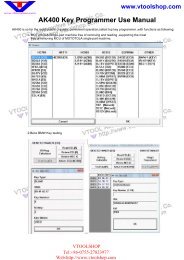
6.2 Program design<br />
The <strong>pro</strong>gram is designed using of a number of elements that are found and look the same throughout the whole<br />
<strong>pro</strong>gram. These are shown in the figure below.<br />
(1) Main menu: This menu contains the following submenus: File, Settings, External <strong>pro</strong>grams, and Help.<br />
Under the menu alternative "File", you find functions to open saved tests and to exit the <strong>pro</strong>gram. Under<br />
Settings there are functions <strong>for</strong> entering workshop in<strong>for</strong>mation, choosing language, as well as configuring<br />
(4)<br />
www.vtoolshop.com<br />
the hardware.<br />
External <strong>pro</strong>grams contains links to third party <strong>pro</strong>grams, if such links are installed.<br />
The last menu alternative, which is Help, contains link to the <strong>pro</strong>gram help, activation of demo mode,<br />
license handling, as well as in<strong>for</strong>mation about the <strong>pro</strong>gram.<br />
(2) At the top right in the <strong>pro</strong>gram window you find general functions such as Generic OBD, a button to start<br />
the Help function, and an activity indicator.<br />
(3) The middle of the <strong>pro</strong>gram shows the work area which is used to, among other things, present in<strong>for</strong>mation.<br />
(4) The left button menu in the <strong>pro</strong>gram is called function menu 1 and contains the different main functions you<br />
can choose. At the bottom in the menu there is a button to go back/exit. The function of the button depends<br />
on where in the <strong>pro</strong>gram you are.<br />
(5) The button menu at the bottom right is called function menu 2 and contains the functions connected to the<br />
main function as well as that which is shown in the work area.<br />
(1)<br />
www.vtoolshop.com<br />
(2)<br />
(3)<br />
(5)<br />
<strong>VtoolShop</strong><br />
Tel:+86-0755-27823977<br />
Email:vtoolshop@gmail.com<br />
Website:http://www.vtoolshop.cm<br />
13
Manual<br />
6.3 Navigation<br />
In order to facilitate navigation in the <strong>pro</strong>gram, there are some supplements to what you normally find in other<br />
<strong>pro</strong>grams. An example is the red marker that shows where in the <strong>pro</strong>gram you are, what you have chosen, or what is<br />
active. The marker is seen as a red frame. The red marker's function varies, depending on if you use the mouse or the<br />
keyboard to move around in the <strong>pro</strong>gram. If you use the keyboard to navigate in the <strong>pro</strong>gram, the red marker moves<br />
directly, e.g., to the button you choose.You can navigate by pressing the TAB-key or the arrow keys. In general, the<br />
arrows are used to navigate within a field or a work area. The TAB-key is used to switch between menus, etc. The<br />
button highlighted by the red marker is activated by pressing Enter . If you use the mouse, a dashed red marker is<br />
moved to the button or component that the mouse is over. First when you have pressed on, e.g., the button, then the<br />
whole red marker moves.<br />
www.vtoolshop.com<br />
www.vtoolshop.com<br />
<strong>VtoolShop</strong><br />
Tel:+86-0755-27823977<br />
Email:vtoolshop@gmail.com<br />
Website:http://www.vtoolshop.cm<br />
14
Manual<br />
7 General functionality<br />
7.1 Program help<br />
The easiest way to access help in the <strong>pro</strong>gram is to press the help button in the <strong>pro</strong>gram,found at the top right.<br />
Another way is to use the key "F1" on the keyboard. The same help in the <strong>for</strong>m of a user <strong>manual</strong> (PDF) is also<br />
available using the start menu.<br />
7.2 Save & print test report<br />
To be able to give the customer a report of what was found and done to the car, it is possible to generate test reports<br />
www.vtoolshop.com<br />
in the <strong>pro</strong>gram. These test reports can either be printed out immediately when you have done the test, or saved <strong>for</strong><br />
future use. If you choose to save a test report, a PDF file is generated. It can be read using Adobe Acrobat Reader,<br />
which can be downloaded <strong>for</strong> free from www.adobe.com.<br />
Two different types of test reports can be saved: OBD-test, as well as Generic OBD. More in<strong>for</strong>mation on its<br />
function is found ahead in the <strong>manual</strong>. To save or print a test report you press the button "Print/Save". The function<br />
may vary, depending which type of test you have chosen to save or print. Common <strong>for</strong> all tests is that you can add<br />
in<strong>for</strong>mation about the test that was done, e.g., in<strong>for</strong>mation about the car, driving distance, or general in<strong>for</strong>mation<br />
about what has been fixed. For OBD-test it is also possible to choose which systems you want to include in the test<br />
report, on the condition that several systems have been tested. This makes it easy to compile a complete test report of<br />
all systems in the car. It is also possible to print the help instructions available <strong>for</strong> certain diagnostic functions.<br />
7.3 Open saved test report<br />
To access saved test reports, the easiest way is to go to the main menu and choose "File" and then "Open saved test".<br />
If the suggested search path has been used to save a test report it is found in the directory that opens. Select test<br />
report to be opened, and click on "Open".<br />
www.vtoolshop.com<br />
7.4 External <strong>pro</strong>grams<br />
Depending on the type of installation and license, the <strong>pro</strong>gram may include links to other external <strong>pro</strong>grams. These<br />
may be, e.g., in<strong>for</strong>mation systems, parts catalogues, etc.<br />
7.5 Demo mode<br />
By enabling the <strong>pro</strong>gram in demo mode you can run most functions in a simulation. Note that regardless of which car<br />
or function you chose, the same simulated in<strong>for</strong>mation and values will be shown. When the <strong>pro</strong>gram is enabled in<br />
demo mode, a dialogue is shown be<strong>for</strong>e you choose function that tells you that the <strong>pro</strong>gram is running in demo<br />
mode.<br />
7.6 License<br />
You need a valid hardware key to be able to use the <strong>pro</strong>gram. Should it be that you need to enter the hardware key at<br />
a later time, go to the main menu and choose "Help", and then "License".<br />
Enter the hardware key consisting of twelve (12) letters and press "OK".<br />
<strong>VtoolShop</strong><br />
Tel:+86-0755-27823977<br />
Email:vtoolshop@gmail.com<br />
Website:http://www.vtoolshop.cm<br />
15
Manual<br />
8 Program configuration<br />
Functions <strong>for</strong> <strong>pro</strong>gram configuration are accessed using the main menu and "Settings".<br />
8.1 Workshop in<strong>for</strong>mation<br />
Under the tab "Workshop" you can change/enter in<strong>for</strong>mation about the workshop as well as add mechanics. This<br />
in<strong>for</strong>mation is used, among others, when you print or save test reports. To add a new mechanic you click on the plus<br />
(+). Then a window appears where you can enter in<strong>for</strong>mation. To delete a mechanic, select the name in the list and<br />
then click on the recycle bin.<br />
8.2 Language<br />
Under the tab "Language" you can choose the languages installed in the <strong>pro</strong>gram. Choose language and then press<br />
"OK" to save the selection. Note that you have to restart the <strong>pro</strong>gram after choosing new language, only then does<br />
the language selection change.<br />
www.vtoolshop.com<br />
8.3 Hardware settings<br />
Under the tab "Hardware configuration" you can set COM-port <strong>for</strong> the diagnostic unit as well as update connected<br />
diagnostic unit with new software (firmware). There are two ways to set COM-port: "Automatic" and "Manual".<br />
If you choose "Automatic", the <strong>pro</strong>gram automatically searches <strong>for</strong> a diagnostic unit to connect to and then shows<br />
in<strong>for</strong>mation about the diagnostic unit that was found. In "Manual" mode, it is possible to <strong>manual</strong>ly choose a specific<br />
COM-port as well as test the connection by pressing "Test". Note that <strong>for</strong> both cases, the diagnostic unit must be<br />
configured to the computer as well as supplied with voltage (power).<br />
If the <strong>pro</strong>gram still does not find a diagnostic unit, you may have to troubleshoot using the unit manager. In that<br />
case, contact your distributor <strong>for</strong> more in<strong>for</strong>mation. Also see the chapter on Computer configuration.<br />
www.vtoolshop.com<br />
<strong>VtoolShop</strong><br />
Tel:+86-0755-27823977<br />
Email:vtoolshop@gmail.com<br />
Website:http://www.vtoolshop.cm<br />
16
Manual<br />
9 Vehicle choice<br />
9.1 Introduction<br />
There are three (3) different ways to choose vehicle: classic mode, in<strong>for</strong>mation/tree structure, as well as history.<br />
From all modes you can chose to start a test. The choice remains when changing between the different display<br />
modes. For example, you can chose vehicle in classic mode and change to in<strong>for</strong>mation/tree structure to get more<br />
detailed in<strong>for</strong>mation.<br />
9.2 Classic mode<br />
In classic mode the different vehicle choices are shown as lists. This alternative gives a fast overview of what<br />
systems there are. Choose the car you want <strong>for</strong> troubleshooting and click on the desired function in function menu 2.<br />
www.vtoolshop.com<br />
9.3 In<strong>for</strong>mation/Tree structure<br />
This mode shows the same in<strong>for</strong>mation as in classic mode, but in addition to that also the diagnostic functions that<br />
can be per<strong>for</strong>med on the vehicle, as well as an in<strong>for</strong>mation section. By right-clicking in the tree structure, you can<br />
choose to start a new test as well as collapse the tree. The in<strong>for</strong>mation section consists of, among others, position of<br />
diagnostic socket, engine code, as well as which cable shall be used. On certain vehicles there is also a photo of the<br />
diagnostic position.<br />
www.vtoolshop.com<br />
9.4 History<br />
This mode shows all previously used vehicles. Sorting is done by clicking on each column. To delete the whole list,<br />
press the recycle bin. To delete a specific vehicle, select the vehicle you want to delete from the list, right-click and<br />
chose "Delete". Note that the list <strong>for</strong> history is deleted when updating the software.<br />
<strong>VtoolShop</strong><br />
Tel:+86-0755-27823977<br />
Email:vtoolshop@gmail.com<br />
Website:http://www.vtoolshop.cm<br />
17
Manual<br />
10 OBD – On Board Diagnostics<br />
10.1 Introduction<br />
A modern vehicle uses electronic control systems, e.g., fuel control systems, brake control systems, climate control<br />
systems, and control systems <strong>for</strong> automatic transmissions to control the vehicle's different functions. The control<br />
systems use a variety of sensors and actuators (input and output signals) to control the control system's function.<br />
When a sensor is defective, it may result in the sensor not being able to report correct in<strong>for</strong>mation to the control<br />
system, which affects the possibility to correctly calculate an output signal to the system's different actuators. This<br />
results in incorrect or lost function <strong>for</strong> the control system.<br />
OBD is really about monitoring these input and output signals to assess the control system's functionality. Thus, in<br />
addition to controlling a certain function in the vehicle based on the control system's input and output signals, the<br />
system has a built-in self-diagnosis, the function of which is to monitor the control system's own function and<br />
indicate to the user that something is wrong. This normally takes place with a flashing system symbol/MIL<br />
(Malfunction Indicator Lamp) in the vehicle's instrumentation, or other indication to the driver that the vehicle<br />
should be brought to a workshop. Thus, the OBD-system indicates that something in the system is wrong, not what<br />
or how serious the fault is. To obtain in<strong>for</strong>mation about what is wrong, a special-purpose tool has to be connected to<br />
the vehicle's diagnostic socket and the required in<strong>for</strong>mation about the system's status has to be read out.<br />
10.2 Connection<br />
Throughout the years, vehicle manufacturers have had different ways of connecting troubleshooting tools to their<br />
vehicles. The connection/connector has been developed in-house to fit the individual vehicle manufacturer's need <strong>for</strong><br />
connection. Since the middle of the nineties several vehicle manufacturers have chosen to use the standardised<br />
diagnostic socket J1962(SAE)/15031-3(ISO), depending on legal requirements in the USA/1996 and in the EU/2001<br />
<strong>for</strong> gasoline-powered vehicles up to 3,500 kg, as well as USA/2004 and EU/2005/2006 <strong>for</strong> diesel-powered vehicles<br />
up to 3,500 kg. The vehicle manufacturer must use the standardised diagnostic socket to enable primarily<br />
government authorities to connect with a general tool and read off statutory emission-related in<strong>for</strong>mation from the<br />
vehicle. This is still not a requirement <strong>for</strong> other control systems in the vehicle, such as brake control systems or<br />
climate control systems,however, a majority of vehicle manufacturers have decided to use one type of connection in<br />
their vehicles.<br />
www.vtoolshop.com<br />
www.vtoolshop.com<br />
10.3 Distributed control systems<br />
Control systems may be so-called distributed control systems, meaning that they handle several system functions in<br />
the vehicle. This is managed in many different ways by different vehicle manufacturers, e.g., by grouping all<br />
functions around the right A-pillar in a control system, such as external rear-view mirror, front side airbag, and door<br />
electronics such as power windows, locks, and side airbag. The designation of such a system may become ”Airbag,<br />
right front”. The designation may be due to the airbag being regarded as the most critical system in the context, but<br />
in<strong>for</strong>mation from the control system may also be related to, e.g., power windows and not only airbag. In cases where<br />
the control system is a so-called distributed control system, this shall be stated in the in<strong>for</strong>mation <strong>for</strong> the chosen<br />
control system in the diagnostic system.<br />
10.4 Diagnostic functions<br />
The diagnostic system is able to per<strong>for</strong>m the functions, ”Read fault codes”, ”Delete fault codes”, ”Real time data”,<br />
”Component activation”, ”Adjust”, and ”Write to ECU”. That which is possible to do depends on what is available in<br />
the control system in question. This varies between different control systems, but also between vehicle<br />
<strong>VtoolShop</strong><br />
manufacturers, where strategies are different <strong>for</strong> what in<strong>for</strong>mation is required to maintain its vehicles on the<br />
aftermarket. The terms ”Read fault codes”, ”Delete fault codes”, ”Real time data”, ”Component activation”,<br />
Tel:+86-0755-27823977<br />
Email:vtoolshop@gmail.com<br />
Website:http://www.vtoolshop.cm<br />
18
Manual<br />
”Adjust”, and ”Write to ECU” are found in this diagnostic system, but may be described differently in other<br />
diagnostic tools available on the market.<br />
10.4.1 DTC - Read fault codes<br />
Fault codes consists of in<strong>for</strong>mation stored when the OBD-system senses that the control system works outside valid<br />
limit value. When the trouble code is stored, in principle this means that the malfunction lamp is lit in the vehicle's<br />
instrumentation. Malfunction lamp is most often not available <strong>for</strong> all control systems in the vehicle, but normally<br />
only <strong>for</strong> systems that affect the vehicle with regards to operation and safety. Other systems store fault codes, but it is<br />
customer requests based on malfunction symptoms in the control system's function that is the basis <strong>for</strong> reading out<br />
fault codes.<br />
Read-outs of fault codes from the vehicle's control system may be presented in different ways depending on how<br />
much in<strong>for</strong>mation that the vehicle's control system can supply. In most cases the presentation shows a fault code<br />
number, component description, and in<strong>for</strong>mation about the fault code's status, that is, if it is ”Permanent” or<br />
”Intermittent”.<br />
Ex.<br />
C1016 Brake light switch, intermittent<br />
www.vtoolshop.com<br />
In some cases there is additional fault description in the <strong>for</strong>m of, e.g., short-circuiting to ground or open circuit.<br />
Ex.<br />
C1016 Brake light switch, intermittent<br />
- Open circuit<br />
More in<strong>for</strong>mation about so-called ”frozen data”, i.e., data that shows parts of the vehicle's status when the <strong>pro</strong>blem<br />
occurred, such as engine temperature or rpm, may appear.<br />
Ex.<br />
C1016 Brake light switch, intermittent<br />
- Open circuit<br />
Vehicle speed 87 km/h<br />
Brake pedal position On<br />
www.vtoolshop.com<br />
Which in<strong>for</strong>mation and to what extent the in<strong>for</strong>mation is presented in the diagnostic system depends on what the<br />
vehicle's control system is able to present.<br />
10.4.2 DTC - Delete trouble codes<br />
”Deleting trouble codes” will delete saved malfunction in<strong>for</strong>mation from the control system's memory. In most cases<br />
the control system's memory is deleted directly, however, there are control systems that first require an action from a<br />
connected diagnostic system, then to be followed by a mechanical action, <strong>for</strong> example. ”Ignition off <strong>for</strong> 10 seconds”<br />
thereafter ”Ignition on”. When mechanical or other action is required, this shall be stated in the in<strong>for</strong>mation <strong>for</strong> the<br />
chosen control system in the diagnostic system. When trouble code recurs immediately when reading trouble codes<br />
after deleting, it is likely that the trouble code is permanent and that the OBD-system senses the malfunction during<br />
its self-test and immediately stores the trouble code again.<br />
<strong>VtoolShop</strong><br />
Tel:+86-0755-27823977<br />
Email:vtoolshop@gmail.com<br />
Website:http://www.vtoolshop.cm<br />
19
Manual<br />
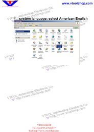
10.4.3 RTD - Real time data<br />
”Real time data” is a partial quantity of the input and output signals that the control system uses to calculate and<br />
regulate its control. Real time data presents how the control system experiences the input signals that are the basis <strong>for</strong><br />
what the output signals should look like.<br />
In diagnostic systems, real time data may be presented in different ways when different input and output signals are<br />
suitable <strong>for</strong> analysis in different ways. For this purpose, the presentation may be a graph or a numerical list. The<br />
predefined groups found in the diagnostic system is the most optimal grouping from an update perspective. That is,<br />
the or those parameters that are presented at the same time are presented/updated as fast as possible. The number of<br />
parameters that are presented together and updating (reading) frequency in the predefined groups vary depending on<br />
the control system's design and not the diagnostic system. Using the diagnostic system, it is possible to create a<br />
”customer defined” group composed of different parameters, and these groups can also be presented in the <strong>for</strong>m of a<br />
graph or numerical list.<br />
www.vtoolshop.com<br />
Note! Creating a ”Customer defined” group may mean that the updating (reading) frequency of real time data<br />
deteriorates radically. Keep this in mind, primarily when presenting components that are to be changed cyclically,<br />
such as lambda (oxygen) sensors. In a worst case, the diagnostic system can update real time data from the lambda<br />
(oxygen) sensor at the same time in its cycle, which then results in presentation of a constant value <strong>for</strong> a component<br />
that is expected to change periodically.<br />
To show display mode, use function buttons (1) and (2). Button (1) to show numerical list and button (2) to show<br />
graphs. Parameters without numerical values, e.g., status Active/Inactive, are shown as text even in graph mode.<br />
Button (3) opens a list with all parameters that are available in the control system. By selecting parameters and<br />
moving to selected parameters with the arrow keys (5) you create a personally defined list. Use the recycle bin (4) to<br />
empty the list. When the list is done, use the buttons (1) and (2) to show the real time data.<br />
www.vtoolshop.com<br />
(5)<br />
(4)<br />
<strong>VtoolShop</strong><br />
(1) (2) (3)<br />
Tel:+86-0755-27823977<br />
Email:vtoolshop@gmail.com<br />
Website:http://www.vtoolshop.cm<br />
20
Manual<br />
10.4.4 ACT - Component activation<br />
”Component activation” is a way <strong>for</strong> the diagnostic system to <strong>for</strong>ce the control system to bypass its own control<br />
function and to let the diagnostic system control/change the output signal. In this way, the diagnostic system can<br />
”<strong>for</strong>ce start”, e.g, the engine's cooling fan. Which components and how activation is designed depends on the control<br />
system's design. In most activation cases the diagnostic system presents a number of components that are possible to<br />
active, the choice of component controls what is activated in the vehicle. It is also possible that the diagnostic system<br />
only has the choice to start the activation, then the control system starts a cyclical activation of different components<br />
<strong>for</strong> the control system, which cannot be affected except that it is possible to cancel the cycle. Some actuators require<br />
a certain vehicle status to be activated, e.g., that the engine is running. The basic mode is always ”Engine<br />
off”/”Ignition on”. If other conditions apply, this is stated either in the connection instructions or in an in<strong>for</strong>mation<br />
dialogue in connection with activation. Certain activations are time-fixed and cannot be cancelled. A sequence<br />
indicator (5) is shown in these cases. In other cases activations are controlled with buttons (1), (2), (3), and (4) in the<br />
work area.<br />
www.vtoolshop.com<br />
(1) (2) (3) (4)<br />
www.vtoolshop.com<br />
(5)<br />
10.4.5 ADJ - Adjust<br />
”Adjust” is an advanced function where the diagnostic system is used to change the control system's functionality,<br />
temporarily turn off functions in the control system, or control system functions in the control system. These<br />
functions may be required to finish replacement/repair of defective components or when doing service work. Be<strong>for</strong>e<br />
an adjustment function is per<strong>for</strong>med, it is important to read through the help instructions and to follow the<br />
instructions in the diagnostic system. Not following instructions and directions from the diagnostic system means<br />
risk of damaging the vehicle's control system.<br />
<strong>VtoolShop</strong><br />
Tel:+86-0755-27823977<br />
Email:vtoolshop@gmail.com<br />
Website:http://www.vtoolshop.cm<br />
21
Manual<br />
10.4.6 COD - Write to ECU<br />
The function ”Write to ECU”, also called coding, is an advanced function where the diagnostic system is sued to add<br />
new in<strong>for</strong>mation to the control system. Examples of coding functions are injector coding, key coding, or replacement<br />
of a complete control system/actuator. Be<strong>for</strong>e a coding function is per<strong>for</strong>med, it is important to read through the help<br />
instructions and to follow the instructions in the diagnostic system. Not following instructions and directions from<br />
the diagnostic system means risk of damaging the vehicle's control system.<br />
10.4.7 ISS (Intelligent System Scan)<br />
www.vtoolshop.com<br />
For some vehicle brands there is ISS (Intelligent System Scan). For the vehicle brands where ISS is available, there<br />
is a system choice which is called “All Systems”, that is always found at the top in the choice of system type.<br />
When you have chosen this system type, the ISS button is activated in the right corner at the bottom.<br />
The function scan through the control systems that are chosen/marked in the list in ISS. The scan is started with the<br />
button in the right corner at the bottom. Communication is established with the control units and the software reads<br />
out fault codes stored in the control systems. The result is presented with one of four colors marked <strong>for</strong> the chosen<br />
control systems.<br />
Green implies that the control system answers correctly and there are no fault codes stored.<br />
Red implies that the control system answers correctly with fault codes stored in the system.<br />
Orange implies that it is not possible to identify the control system in a single-valued way. The user must<br />
make a choice.<br />
Grey implies that the control system does not answer.<br />
www.vtoolshop.com<br />
To see the stored fault codes, click on the arrow <strong>for</strong> each respective system. It is possible to erase fault codes by<br />
clicking on the symbol <strong>for</strong> erasing fault codes in the right corner at the bottom. It is also possible to go straight to<br />
complete OBD. There are further instructions in the software <strong>for</strong> each respective part.<br />
Glossary<br />
Permanent: Irreversible – Present<br />
Intermittent: Periodically recurring – Comes and goes<br />
OBD: On Board Diagnostics<br />
MIL: Malfunction Indicator Lamp – Lamp <strong>for</strong> indicating malfunction<br />
DTC: Diagnostic Trouble Code – Fault code<br />
RTD: Real Time Data – Real time data<br />
ACT: Activation – Activation<br />
ADJ: Adjustment – Adjustment<br />
COD: Coding – Coding<br />
ECU: Electronic Control Unit – Control system, controller (actuator)<br />
SAE: Society of Automotive Engineers<br />
<strong>VtoolShop</strong><br />
ISO: International Organization <strong>for</strong> Standardization<br />
Tel:+86-0755-27823977<br />
Email:vtoolshop@gmail.com<br />
Website:http://www.vtoolshop.cm<br />
22
Manual<br />
11 Generic OBD<br />
11.1 Introduction<br />
Generic OBD is a <strong>pro</strong>gram used to read out data from the car's built-in statutory diagnostic function, the primary<br />
function of which is to monitor emission-related components' function. In Europe this standard function is called<br />
eOBD, in the USA it is called OBD2, and in Japan it is called JOBD. We have decided to collect these standards in<br />
one and the same software. It also contains all standards <strong>for</strong> reading out statutory OBD on heavy vehicles.<br />
11.2 Connecting to vehicle<br />
Immediately when GOBD is chosen, either using the function key in the top right corner or using the car selection,<br />
connection to the vehicle is started. There<strong>for</strong>e, it is important that the vehicle has been prepared <strong>for</strong> diagnosis be<strong>for</strong>e<br />
www.vtoolshop.com<br />
you press the button. The vehicle shall have the ignition on or the engine running to enable connection to all systems.<br />
11.3 General use of the <strong>pro</strong>gram<br />
The <strong>pro</strong>gram is controlled using the function buttons in function menu 1, function menu 2, and with buttons in the<br />
work area. Each function/mode is described below. Generic OBD is available in two user levels. To change level, go<br />
to the Settings menu and select/deselect “Generic OBD Advanced mode”. When the <strong>pro</strong>gram is in Advanced mode<br />
all functions are available. In User mode functions <strong>for</strong> legislated verification of the vehicle manufacturer is hidden.<br />
We highly recommend User mode <strong>for</strong> use in workshops and with the intention to diagnose the vehicle. Note that<br />
when the car does not support chosen function/mode, then ”not supported by vehicle” is shown.<br />
11.3.1 In<strong>for</strong>mation<br />
www.vtoolshop.com<br />
The first window that appears is the in<strong>for</strong>mation window containing general in<strong>for</strong>mation about the vehicle you are<br />
connected to.<br />
Available control units. The list with available control units includes all those control units that support the eOBD<br />
standard.<br />
In<strong>for</strong>mation. In the list under the heading in<strong>for</strong>mation, specific data is shown <strong>for</strong> the chosen ECU. To choose<br />
another ECU, click on it in the list with available control units. This box shows three different values, such as:<br />
MIL status, quantity of fault codes (permanent), as well as which communication standard is being used.<br />
Main in<strong>for</strong>mation. Main in<strong>for</strong>mation shows which communication type that the vehicle uses to communicate and<br />
the total quantity of fault codes from all control units. This also shows if the MIL is lit.<br />
Readiness tests. The list <strong>for</strong> readiness tests shows tests <strong>for</strong> chosen ECU, and if they are supported by the control<br />
unit. The different values that can be assumed are done or not done. The following tests are standard in OBD<br />
II/eOBD:<br />
• Misfires<br />
• Fuel system<br />
• Component test<br />
• Catalytic converter<br />
• Preheated catalytic converter<br />
<strong>VtoolShop</strong><br />
23<br />
• EVAP<br />
• Secondary air system<br />
• AC-system<br />
• Preheated lambda (oxygen) sensor<br />
• EGR-system<br />
Tel:+86-0755-27823977<br />
Email:vtoolshop@gmail.com<br />
Website:http://www.vtoolshop.cm
Manual<br />
11.3.2 Reading fault codes<br />
This lists both permanent and intermittent fault codes from the control units that support the eOBD standard. They<br />
are shown with ECU-number, fault code number, as well as a description of the fault code in plain text.<br />
Permanent fault codes (1). The fault codes shown in this list are stored fault codes.<br />
Intermittent fault codes (2). The fault codes shown in this list are fault codes that must be set <strong>for</strong> a certain<br />
time or a certain number of times to be stored as a permanent fault code.<br />
It is possible to save and print a list with fault codes (3).<br />
www.vtoolshop.com<br />
www.vtoolshop.com<br />
(1)<br />
(2)<br />
(3)<br />
11.3.3 Deleting diagnostic in<strong>for</strong>mation<br />
With this function you can delete fault codes and diagnostic in<strong>for</strong>mation. Pressing the button delete will delete the<br />
fault codes shown under reading fault codes. If this should fail, a message is shown detailing which control units<br />
have deleted successfully and which have failed to delete. If all control units successfully delete diagnostic<br />
in<strong>for</strong>mation, a message is shown telling you that all went well. This function not only deletes fault codes, it also<br />
deletes the readiness tests as well as frozen data. To per<strong>for</strong>m the readiness tests again, the car has to be run through<br />
driving cycles. Some tests are more advanced than other, and there<strong>for</strong>e take longer time to complete.<br />
<strong>VtoolShop</strong><br />
Tel:+86-0755-27823977<br />
Email:vtoolshop@gmail.com<br />
Website:http://www.vtoolshop.cm<br />
24
Manual<br />
11.3.4 Real time parameters<br />
Here you can read data from the chosen ECU and chosen value. The values are updated continuously. If a value is<br />
chosen the activity indicator will start to spin again in the top right corner of the window that indicates that<br />
continuous reading from the vehicle is in <strong>pro</strong>gress.<br />
11.3.4.1 Data list<br />
The function consists of three different parts, Values, Current data, and In<strong>for</strong>mation. The value list lists the real time<br />
parameters that the user can chose, arranged per ECU. The current data list includes the chosen values that the user<br />
has chosen, and the in<strong>for</strong>mation box shows in<strong>for</strong>mation about the values that have additional explanation. To be able<br />
to see a value, it must be chosen in the box under the heading values. All these values do not have a number value as<br />
a result, it may also be a text message, or a value that refers to a text. In order to know if the value refers to a text or a<br />
specific value, you can check this in the column <strong>for</strong> unit. If it reads INFO, you can click on this row and in<strong>for</strong>mation<br />
about the value is shown in the box <strong>for</strong> in<strong>for</strong>mation.<br />
11.3.4.2 Graph<br />
Another function is that you can see a graph of up to three chosen values from the list <strong>for</strong> current data. To chose<br />
these, click on the row in the current data list with the value you are interested in. If it is not chosen this may be due<br />
to that the chosen value cannot be shown in a graph. A hint in<strong>for</strong>ming that the value cannot be chosen is shown to get<br />
quick in<strong>for</strong>mation about this. Then, when one to three values are chosen in the list you can press on the tab graph.<br />
When this is done, the graph is shown. With the graph function it is possible to stop and start the graph. It is also<br />
possible to go to the beginning or end of the graph. Min. and Max. values change continuously during the graph<br />
cycle.<br />
www.vtoolshop.com<br />
www.vtoolshop.com<br />
11.3.5 Frozen data<br />
Here you can read stored data values belonging to permanent fault codes from different control units. Control units<br />
with stored fault codes are shown in the list ”Available control units”. Values belonging to a chosen ECU are shown<br />
in a list. When the fault code is set, current data is stored in the control unit, which then can be read out and used<br />
when troubleshooting the vehicle. The list number states which list is shown. A fault code can store up to 255<br />
different lists. The user can scroll between these lists with the buttons Previous and Next.<br />
<strong>VtoolShop</strong><br />
Tel:+86-0755-27823977<br />
Email:vtoolshop@gmail.com<br />
Website:http://www.vtoolshop.cm<br />
25
Manual<br />
11.3.6 Lambda<br />
In Lambda you can read out values from the lambda (oxygen) sensor. Values that can be chosen are found in the list<br />
”Oxygen sensors”. These can be chosen and are then added to the list ”Values”, where they are read continuously.<br />
The recycle bin empties the list with values.<br />
11.3.7 Non-continuous tests<br />
These test values are read when the button <strong>for</strong> the function is pressed down and are indicated with TID- and CIDnumbers<br />
that are defined by the vehicle supplier. The column Results indicates if the test has an ap<strong>pro</strong>ved value or a<br />
non-ap<strong>pro</strong>ved value. If there are no limit values, then ”---” is shown in the column. To interpret the values, the user<br />
www.vtoolshop.com<br />
of the <strong>pro</strong>gram is referred to the vehicle's documentation.<br />
11.3.8 Diagnostic check<br />
The list ”Tests” includes the tests that are available per ECU. The standardised functions are presented with a text,<br />
while others are presented with TID-number and the text ”Car specific”. To see a test, click on the test in the list.<br />
Then the test will be moved to the value list. The recycle bin empties the list with tests.<br />
www.vtoolshop.com<br />
11.3.9 Car in<strong>for</strong>mation<br />
This function can show three manufacturer-specified values per ECU, and these are:<br />
• Chassis number<br />
• Calibration identification number<br />
• Calibration verification number<br />
<strong>VtoolShop</strong><br />
Tel:+86-0755-27823977<br />
Email:vtoolshop@gmail.com<br />
Website:http://www.vtoolshop.cm<br />
26
Manual<br />
12 Technical specification<br />
• Meets EU Directive 89/336/EEG and 73/23/EEG<br />
• Dimensions: 180 x 90 x 30 (mm)<br />
• Weight: 0.5 kg<br />
• Voltage feed: 10-32 Volt<br />
• Current consumption: 100 mA<br />
• Operating temperature: 0-50 ºC<br />
www.vtoolshop.com<br />
www.vtoolshop.com<br />
<strong>VtoolShop</strong><br />
Tel:+86-0755-27823977<br />
Email:vtoolshop@gmail.com<br />
Website:http://www.vtoolshop.cm<br />
27