U10 - VAHLE, Inc
U10 - VAHLE, Inc
U10 - VAHLE, Inc

Create successful ePaper yourself
Turn your PDF publications into a flip-book with our unique Google optimized e-Paper software.
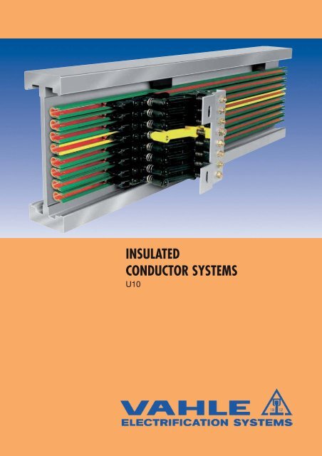
INSULATED<br />
CONDUCTOR SYSTEMS<br />
<strong>U10</strong>
INSULATED CONDUCTORS U 10<br />
Index<br />
Page<br />
Basic description 3<br />
Insulated conductors 4<br />
Feed-in joint splice 5<br />
Expansion section 5<br />
Isolating assembly 5<br />
Transfer guide 6<br />
Compact hanger 7<br />
Locating clamp 7<br />
Transfer funnels 8<br />
Collectors 8-9<br />
Brushes, accessories 10<br />
Spare Parts & brush wear indicator 11<br />
Installation tools 12,13<br />
Questionnaire 14<br />
Slipring units made up from U 10 see leaflet no. 102 s.<br />
<strong>VAHLE</strong> on duty for the automotive industry<br />
2
INSULATED CONDUCTORS U 10<br />
General<br />
<strong>VAHLE</strong> insulated conductors U 10 are designed in accordance with<br />
today’s international safety requirements. They fully meet VDE 0100<br />
and are finger safe to VDE 0470, part 1, protection code IP 21.<br />
For the collectors is the finger safety only valid if the carbons are<br />
complete in the conductor. In hand areas, in which the collectors<br />
leave the conductor due to operating conditions, it must be a<br />
protection against contact installed on site. (i.e. barriers or<br />
cut-off) This is only necessary for voltages over 25 Volts AC or<br />
60 Volts DC.<br />
The adjacent picture demonstrates that the VDE test finger cannot<br />
reach life conductors – finger safety is guaranteed.<br />
The shroud which envelopes the various conductors<br />
is an excellent insulator. Therefore our unipole<br />
insulated conductors guarantee utmost safety<br />
in operation.<br />
Any number of conductors can be installed side<br />
by side at minimum space requirement.<br />
Standard rail sections are 6 m long, shorter sections<br />
are available.<br />
The grounding conductor is marked with a continous<br />
yellow stripe at the isolating housing. The<br />
non-interchangeability of the collector ground and<br />
phases is guaranteed.<br />
Usage: Only for indoor systems<br />
Approved and listed by:<br />
UL. Consult factory label service.<br />
Hangers<br />
Bolted, snap-in and quarter turn type hangers are available.<br />
Standard support distance for U 10 is 600 mm, in curves<br />
300 mm.<br />
Joints<br />
Feed joint splices provide mechanical end electrical continuity. They<br />
include insulated protection covers.<br />
Expansion joint sections are only required in case of expansion<br />
joints in the monorail track.<br />
Engineering data of shroud<br />
Feed terminals<br />
Joint assembly and mid-rail assembly feeds are available.<br />
Furthermore transfer guides and isolating assemblies allow for<br />
spade connectors.<br />
Transfer guides<br />
Transfer guides serve as an end protection of system runs and<br />
accomplish smooth collector transfer in case of switches, drop<br />
sections etc. They can be supplied with or without feed clip.<br />
Isolating assemblies<br />
Isolating sections are electrical interrupts of the conductor.<br />
Under normal operating conditions a cross over with collectors<br />
to switch the voltage off or on is only allowed with low power<br />
ratings (control current).<br />
Conductor isolating assemblies are available for sectionalizing<br />
control circuits, maintenance bays etc. They can be supplied with<br />
or without feed clip.<br />
Curves<br />
Insulated conductors U 10 can be used for horizontal or vertical curves.<br />
A special curve tool for individual field preparation is available.<br />
Collectors<br />
The current collectors are made of re-inforced polyamide/polycarbonate<br />
and stainless steel parts. The current is drawn with a<br />
carbon brush.<br />
The length of the collector connecting cable does not exeed 3 m,<br />
if the prepend overload protection is not suitable for the load of<br />
the connecting cable. Please refer to DIN VDE 0100, Part 430 and<br />
DIN EN 60204-32.<br />
(Note: Above mentioned takes often place in systems with multi<br />
collectors)<br />
The delivered connecting cables are suitable for the mentionend<br />
nominal currents. For the different laying systems please consider<br />
the reduction factors according to DIN VDE 0298-4.<br />
Safety advise<br />
It must be ensured that the arrangement of the conductor system<br />
provides minimum distances (0,5 m) between fixed and mobile<br />
plant parts (i.e. between conductor rails, collector trolleys and<br />
towing arms) so as to avoid the risk of pinching.<br />
standard shroud<br />
color green<br />
high temp. shroud<br />
color gray<br />
Electrical properties:<br />
Di-electric strength DIN 53481 > 25 kV/mm > 25 kV/mm<br />
Specific resistance IEC 60093 > 1 x 10 16 Ohm x cm > 1 x 10 14 Ohm x cm<br />
Surface resistance IEC 60093 2,1 10 15 Ohm 2 10 15 Ohm<br />
Comparable figure / tracking according to IEC 60112 CTI 400 - 1,1 CTI 400 - 1,1<br />
Mechanical properties:<br />
Flexible strength according to ISO 178 74-85 N/mm 2 95 N/mm 2 ± 10 %<br />
Tensile strength according to ISO 178 44-55 N/mm 2 47-65 N/mm 2<br />
Ultraviolet resistance Xenon test > 1500<br />
Max relativ humidity < 100 %<br />
Temperature resistance: (2) – 30 °C up to + 55 °C – 30 °C up to +85 °C<br />
Flame test proof<br />
no flaming particles, self extinguishing, UL 94 V0<br />
Resistance to chemicals: (1) gasoline hydrochloric acid. concentr.<br />
mineral oil<br />
caustic soda solution 25% and<br />
grease 50%, sulphuric acid to 50%<br />
(1)<br />
(2)<br />
Consult factory when synthetic oil and grease involved.<br />
For use below 0 °C continous temperature (deep freeze storage) please contact the factory.<br />
3
INSULATED CONDUCTORS U 10<br />
11,2<br />
5,5<br />
17,5<br />
R H<br />
Radius<br />
horizontal curve<br />
Conductor code:<br />
U = unipole insulated conductor<br />
10 = shroud size<br />
25 = conductor cross sectional<br />
area (mm 2 )<br />
C = copper conductor<br />
E = stainless steel conductor<br />
Length:<br />
6 m is standard length,<br />
shorter lengths are available<br />
Support spacing:<br />
for straight runs 0.6 m<br />
for curves 0.3 m<br />
Conductor spacing:<br />
on compact hangers 14 mm<br />
or variable<br />
Bending of conductor:<br />
Without prebending R 50000 mm<br />
On site:<br />
Horizontal curves 5000 mm R 750 mm<br />
Inside-/Oustside curves 5000 mm R 750 mm<br />
Factory<br />
750 mm R 300 mm<br />
Chemical and electrical properties<br />
see page 3<br />
Use:<br />
Only indoor<br />
Type U 10/25 C U 10/25 E<br />
Weight kg/m 0,267 0,246<br />
Standard shroud, color green<br />
Order- No. phase (1) 167 00 • 167 02 •<br />
Order- No. ground (1) 167 06 • 167 08 •<br />
High temperature shroud, color gray<br />
Order- No. phase (1) 167 03 • 167 05 •<br />
Order- No. ground (1) 167 09 • 167 11 •<br />
Engineering data<br />
Conductor rail<br />
Type<br />
Cross sectional area<br />
mm 2<br />
Copper<br />
stainless<br />
Leakage distance<br />
of covers<br />
mm<br />
Nominal<br />
Voltage (3)<br />
V<br />
Continuous ampere<br />
capacity<br />
A<br />
Resistance<br />
Ohm/1000 m<br />
Impedanz (2)<br />
Ohm/1000 m<br />
U 10/25 C 25 30 690 100 0,744 0,748<br />
U 10/25 E 25 30 690 10 31,328 31,328<br />
Selection of Conductors<br />
in accordance to ampere load and environmetal conditions<br />
U 10/25 C copper conductor for power-, control- and data-transmission.<br />
U 10/25 E stainless steel conductor for control and data-transmission in corrosive atmospheres.<br />
Feed joint (max. 2 x 40 A continous current)<br />
Balances the length extension during temperature fluctuation.<br />
Connecting cable for UEV 10<br />
max. Connection Connection cable<br />
current load cross section with flat plug<br />
A mm 2 Order- No.<br />
2x32 2x2,5 165 049<br />
2x40 2x4,0 165 051<br />
2x40 2x6,0 166 368<br />
60<br />
90<br />
7,5<br />
Type Weight/kg Order-No.<br />
UEV 10 0,020 165 006<br />
120<br />
4<br />
(1) Fill-in last number (1, 2, 3, 4, 5 or 6 m suffix) in accordance to bars required.<br />
(2) Based on 14 mm conductor spacing and with 50 Hz.<br />
(3) Not with UL approval; U UL = 600 V
COMPONENTS U 10<br />
Feed terminal (max. 2 x 50 A continous current)<br />
Connecting cable for UES 10<br />
max. current Connection Connecting cable<br />
current load cross section with flat plug<br />
A mm 2 Order-No.<br />
2x32 2x2,5 165 049<br />
2x40 2x4,0 165 051<br />
2x50 2x6,0 166 368<br />
2 x Flat plug 6.3 x 0.8 mm<br />
UES 10<br />
(without joint<br />
cap)<br />
60<br />
90<br />
Type Weight/kg Order- No.<br />
UES 10 (1) 0,023 165 212<br />
7,5<br />
Usage: UES10 installed on the conductor section between the<br />
joint feeds.<br />
Isolating assembly<br />
Connecting cable for SE 10<br />
max. current Connection Connecting cable<br />
current load cross section with flat plug<br />
A mm 2 Order-No.<br />
1x32 1x2,5 165 049<br />
1x40 1x4,0 165 051<br />
1x40 1x6,0 166 368<br />
120<br />
Type symbol Weight comprising Order- No.<br />
kg<br />
133<br />
LT /LT -U 10 0,010 2 x LT/U 10 165 025<br />
LT /LTE-U 10 (1) 2 x LT/U 10<br />
0,015<br />
units w/1 feed<br />
165 114<br />
LTE/LTE-U 10 (1) 2 x LTU 10<br />
0,020<br />
units w/2 feed<br />
165 026<br />
separately available<br />
SE 10 feed clip<br />
0,005 1x 165 178<br />
→<br />
→ →<br />
The two transfer button elements are pressed together to form<br />
a rigid, well aligned unit.<br />
7,5<br />
Isolating assembly LT/LTE-<strong>U10</strong><br />
23<br />
w/o cond.<br />
SE 10 with flat plug connection 6,3 x 0,8 mm<br />
(max. 40 A continous current)<br />
Expansion section<br />
factory assembled to 0.8 m long conductor section incl. one joint splice. The 0.8 m expansion assembly is part of the system length<br />
Type<br />
Weight<br />
kg<br />
Order- No.<br />
Standard shrouding<br />
color green<br />
High temp. shrouding<br />
color gray<br />
phase ground phase ground<br />
UDV 10/25 C 0,254 165 192 165 193 165 254 165 255<br />
UDV 10/25 E 0,237 165 252 165 253 165 258 165 259<br />
7,5<br />
120<br />
800 (+30 mm expansion capacity)<br />
(1) Connecting cable with flat pin bushing FLA or FKA have to be ordered seperatly (See page 11).<br />
5
COMPONENTS U 10<br />
Transfer guide<br />
with or without feed terminal (also serving for end cap and for anchor point in conjunction with BFU).<br />
37<br />
24,5<br />
BFU 10 A<br />
transfer guide<br />
US 10 S (oblique)<br />
43,5<br />
18,7<br />
BFU 10 B<br />
transfer guide<br />
US 10 (straight)<br />
3,7<br />
45°<br />
max.<br />
6<br />
20 35<br />
max. 42 35 20<br />
79 67<br />
grinding surface 16,5<br />
25<br />
12 w/o cond.<br />
67<br />
7,5<br />
w/o feed: US 10<br />
max. vertical and horizontal offset: ± 3 mm to each other<br />
Type Weight feed clip Order- No.<br />
kg<br />
US 10 0,004 w/o 165 008<br />
US 10 S 0,005 w/o 165 009<br />
USE 10 (2) 0,009 c/w 165 010<br />
USE 10 S (2) 0,010 c/w 165 011<br />
Feed clip only<br />
SE 10<br />
0,005 165 178<br />
24<br />
w/o cond.<br />
79<br />
c/w feed: USE 10 S<br />
(feed cable 6.3 x 0.8 mm)<br />
Anchor bar for transfer guide (Aluminium)<br />
for bolting to the track, consisting of 1 aluminium profile bar, 2 hex. screws M 5 w/washer, 2 locking pins 2 x 20.<br />
used in conjunction with bolted hangers<br />
BFU 10 A<br />
70<br />
M 5 x 20<br />
10<br />
For compact hanger to bolt (1)<br />
Use with oblique cut of the conductor.<br />
(see sketch above left).<br />
BFU 10 B<br />
70<br />
M 5 x 14<br />
25<br />
14,8<br />
14,5<br />
A<br />
A<br />
(16.5 mm distance between conductor-surface and track) (16.5 mm distance between conductor-surface and track)<br />
Type poles A/mm Weight Order- No.<br />
kg<br />
BFU 10 A- 8 1- 8 118 0,042 165 168<br />
BFU 10 A-10 1-10 143 0,052 165 176<br />
Type poles A/mm<br />
Weight<br />
kg<br />
Order- No.<br />
BFU 10 B- 8 (1) 1- 8 118 0,087 165 272<br />
BFU 10 B-10 (1) 1-10 143 0,101 165 274<br />
used in conjunction with snap-in and quarter turn hangers<br />
BFU 10<br />
70<br />
M 5 x 14<br />
8,5<br />
10<br />
A<br />
(10 mm distance between conductor-surface and track)<br />
Type poles A/mm<br />
Weight<br />
kg<br />
Order- No.<br />
BFU 10- 8 1- 8 118 0,022 165 115<br />
BFU 10-10 1-10 143 0,026 165 123<br />
6<br />
(1)<br />
(2)<br />
VB-Type anchor bar essential for more than 15 mm distance between conductor-surface and track on oblique cut tracks.<br />
Connecting cable with flat plug FLA is to be ordered separately (see page 10).
COMPACT HANGERS AND LOCATING CLAMPS FOR U 10<br />
Any number of conductors can be assembled by combining the compact hangers.<br />
Compact hanger with hardware,<br />
for up to 10 conductors<br />
Conductor spacing 14 mm<br />
Hanger KA 10 is for direct bolting<br />
Hanger KH 10 to go with bracket profile<br />
b<br />
L<br />
M5 x 7 deep<br />
a<br />
18<br />
32,5<br />
+1,5<br />
40<br />
250<br />
210<br />
KA 10 …<br />
Phase distance:<br />
Standard = 14 mm<br />
KH 10-10 N<br />
Type Poles Length Weight Order- No.<br />
engaged L a b kg Order- No.<br />
KH 10-10 N 10 141 - - 0,295 142 077<br />
Type Poles Length Weight Order- No.<br />
engaged L a b kg<br />
KA 10- 2 N 2 29 0 20,5 0,012 142 072<br />
KA 10- 4 N 4 57 42 7,5 0,024 142 073<br />
KA 10- 6 N 6 85 42 21,5 0,033 142 757<br />
KA 10- 8 N 8 113 42 35,5 0,045 142 075<br />
KA 10-10 N 10 141 100 20,5 0,056 142 076<br />
Compact hanger, self-locking, for up to 10 conductors on special order to fit your monorail track<br />
Compact hanger incl. holder for support<br />
profile with barcode band<br />
Compact hanger incl. holder for support<br />
profile with barcode band and leaky feeder<br />
snap-in & quarter turn type hangers for typical monorail track electrification<br />
for each anchor point use<br />
one bolted hanger with<br />
2 locating clamps per<br />
conductor bar<br />
Locating clamp<br />
Type Weight /kg Order- No.<br />
USK 10 0,030 165 645<br />
7
88<br />
TRANSFER FUNNELS<br />
AND CURRENT COLLECTORS FOR U 10<br />
Transfer Funnels for KUFU 25<br />
90<br />
4<br />
335<br />
15 °<br />
10<br />
67<br />
16,5<br />
C<br />
A<br />
14 14 14 14 14 14 14<br />
B<br />
D<br />
max. 600<br />
15<br />
7<br />
30<br />
154,5 62,5<br />
Type A mm B mm C mm D mm Weight kg Order- No.<br />
EFT U 10- 2-KUFU 36 94 82 136 1,145 167 675<br />
EFT U 10- 3-KUFU 50 108 96 150 1,230 167 676<br />
EFT U 10- 4-KUFU 64 122 110 164 1,315 167 677<br />
EFT U 10- 5-KUFU 78 136 124 178 1,400 167 678<br />
EFT U 10- 6-KUFU 92 150 138 192 1,485 167 679<br />
EFT U 10- 7-KUFU 106 164 152 206 1,570 167 680<br />
EFT U 10- 8-KUFU 120 178 166 220 1,655 167 681<br />
EFT U 10- 9-KUFU 134 192 180 234 1,740 167 682<br />
EFT U 10-10-KUFU 148 206 194 248 1,825 167 683<br />
Compact-collector KUFU 25<br />
for transfer funnel EFT <strong>U10</strong><br />
with 1m connecting cable<br />
max. current load: 1 flat plug 25 A<br />
max. 138<br />
10 9 8 7 65 4<br />
3<br />
2 1<br />
14<br />
Phase distance 14 mm<br />
Lift and swivel +/- 15 mm<br />
Contact pressure:<br />
approx. 3.5 N per carbon<br />
Ground at Pos.4, with 3 poles at Pos. 3<br />
other arrangements on request<br />
Ground is always first contact<br />
plug<br />
terminal<br />
6,3 x 0,8<br />
for FLA 2,5<br />
a<br />
b<br />
c<br />
15<br />
7<br />
RF 3<br />
42 15<br />
71<br />
max. 18<br />
DF 2<br />
Type<br />
Order- No.<br />
Poles dim. a dim. b dim. c weight base plate for power w/1 ground for control<br />
mm mm mm kg HS ST<br />
KUFU 25- 2 2 – 34 - 0,244 2-pole 168 040 168 051<br />
KUFU 25- 3 3 28 62 - 0,378 4-pole (Nr. 4 = blank) 168 041 168 052<br />
KUFU 25- 4 4 28 62 - 0,479 4 pole 168 042 168 053<br />
KUFU 25- 5 5 56 90 - 0,617 6-pole (Nr. 6 = blank) 168 043 168 054<br />
KUFU 25- 6 6 56 90 - 0,718 6-pole 168 044 168 055<br />
KUFU 25- 7 7 80 118 53 0,826 8-pole (Nr. 8 = blank) 168 045 168 056<br />
KUFU 25- 8 8 80 118 53 0,927 8-pole 168 046 168 057<br />
KUFU 25- 9 9 80 146 53 1,060 10-polie (Nr. 10 = blank) 168 047 168 058<br />
KUFU 25-10 10 80 146 53 1,161 10-pole 168 048 168 059<br />
Single unit: phase black ground yellow<br />
collector KUFU 25 0,068 168 015 168 016<br />
8
COLLECTORS FOR U 10<br />
Compact double collector KDS 2/40<br />
(two-way conveying) (1)<br />
for conductor spacing of 14 mm<br />
Ampacity: 1 Plug terminal 25 A<br />
2 Plug terminals 2 x 20 A<br />
swivel ± 15 mm · lift ± 15 mm;<br />
contact pressure ca. 3.5 N per brush<br />
feed cable WFLA 2.5 mm 2<br />
0.5 m long high-flexible incl.<br />
ground at No. 4, 3-pole at No. 3,<br />
other positions on request.<br />
For safety reasons during maintenance<br />
ground collector is always first and last contact.<br />
14<br />
98<br />
8<br />
7<br />
6<br />
5<br />
GF 1<br />
DF 3<br />
4<br />
3<br />
2<br />
plug<br />
terminal<br />
6,3 x 0,8<br />
for WFLA 2,5<br />
1<br />
c<br />
a<br />
b<br />
15<br />
max. 145<br />
7<br />
42<br />
72<br />
plug<br />
terminal<br />
6,3 x 0,8<br />
quick connect plug<br />
and flexible cable<br />
WFLA 2,5 mm 2<br />
L = 0,5 m incl.<br />
max. 12<br />
15<br />
DF 1<br />
Type<br />
Poles dim. a dim.b dim. c Weight base plate<br />
Order- No.<br />
mm mm mm kg for power w/1 ground for control<br />
KDS 2/40- 1-14 1 28 62 - 0,170 4-pole (Nr. 2-4 = blank) 168 079 168 091<br />
KDS 2/40- 2-14 2 28 62 - 0,240 4-pole (Nr. 3+4 = blank) 168 080 168 092<br />
KDS 2/40- 3-14 3 28 62 - 0,310 4 pole (Nr. 4 = blank) 168 081 168 093<br />
KDS 2/40- 4-14 4 28 62 - 0,380 4-pole 168 082 168 094<br />
KDS 2/40- 5-14 5 56 90 - 0,490 6-pole (Nr. 6 = blank) 168 083 168 095<br />
KDS 2/40- 6-14 6 56 90 - 0,560 6-pole 168 084 168 096<br />
KDS 2/40- 7-14 7 80 118 53 0,675 8-pole (Nr. 8 = blank) 168 085 168 097<br />
KDS 2/40- 8-14 8 80 118 53 0,745 8-pole 168 086 168 098<br />
KDS 2/40- 9-14 9 80 146 53 0,860 10-pole (Nr. 10 = blank) 168 087 168 099<br />
KDS 2/40-10-14 10 80 146 53 0,930 10-pole 168 088 168 100<br />
KDS 2/40-11-14 11 120 174 80 1,020 12-pole (Nr. 12 = blank) 168 089 168 101<br />
KDS 2/40-12-14 12 120 174 80 1,090 12-pole 168 090 168 102<br />
Single unit: phase black ground yellow<br />
collector KDS 2/40 1 0,070 w/o 168 073 168 074<br />
Double Collector (1)<br />
Ampacity: 1 Plug terminal 25 A<br />
2 Plug terminals 2 x 20 A<br />
80<br />
plug<br />
terminal<br />
6,3 x 0,8<br />
for FLA 2,5<br />
35<br />
102<br />
85<br />
ca. 14<br />
plug<br />
terminal<br />
6,3 x 0,8<br />
for WFLA 2,5<br />
ZF 2<br />
ca. 70<br />
M 5, phase<br />
M 6, ground<br />
swivel ± 10 mm · lift ± 10 mm;<br />
contact pressure 3.5 N per brush<br />
feed cable FLA 2.5 or WFLA 2.5 is to be ordered separately.<br />
(see page 11)<br />
Type Weight Order- No.<br />
kg phase black ground yellow<br />
KST 2/40 0,080 168 137 168 138<br />
(1)<br />
Replaces obsolete KUF and KUFR collectors<br />
9
COLLECTOR & COMPONENTS FOR U 10<br />
Copper-graphite brush assembly<br />
66<br />
50<br />
102<br />
85<br />
35<br />
23<br />
RH<br />
23<br />
RH<br />
10<br />
10<br />
KMKU 25/14 KMK 2/40<br />
102<br />
85<br />
GF 1<br />
GF 1<br />
35<br />
23<br />
RH<br />
10<br />
DS 2/40<br />
DSW 2/40<br />
Dim. RH = allowed rest of hight<br />
3,8 mm width of all copper-graphite brushes<br />
Type for collectors RH/mm Weight kg Order- No.<br />
KMKU 25/14 KUFU 25 3,00 0,035 168 000<br />
KMK 2/40 KST 2/40 3,00 0,050 168 135<br />
DS 2/40 KDS 2/40 3,00 0,050 168 065<br />
DSW 2/40 (2) KDS 2/40 3,00 0,050 168 151<br />
Springs<br />
S<br />
S<br />
S<br />
D<br />
D<br />
D<br />
L<br />
Pressure Spring DF 3<br />
L<br />
Pressure Spring DF 1<br />
Guiding Spring GF<br />
L<br />
Tension Spring ZF / RF<br />
Type for collectors<br />
S D L<br />
mm mm mm<br />
Order- No.<br />
DF 1 KDS 2/40 1,00 7,00 38,00 153 847<br />
DF 2 KESR 0,90 7,70 43,00 153 848<br />
DF 3 KDS 2/40 0,55 9,55 24,00 152 011<br />
RF 3 KUFU 25, KESR 0,40 4,40 31,00 153 849<br />
ZF 2 KST 2/40, KSTF 2/40 0,85 6,45 24,00 153 515<br />
GF 1 KDS, KSTF 0,35 2,00 22,00 153 850<br />
10<br />
(1)<br />
(2)<br />
Install collector in dragging position when equipment moves one way only.<br />
Also for obsolete KUF 2/40 and KUFR 2/40.
85<br />
CONNECTING CABLES, CONNECTING BOXES AND<br />
BRUSH WEAR INDICATOR FOR U 10<br />
Connecting cable, high flexible<br />
for collectors, feed terminals, transfer guides and isolating assemblies (for collector KDS, connecting cable WFLA 2.5)<br />
WFH<br />
WFLA<br />
0.5 m long with quick connect plug 6.3 x 0.8<br />
Longer cable available.<br />
Heavy double insulation<br />
FLA (FKA)<br />
Type<br />
Cross A Weight<br />
Bestell-Nr..<br />
section<br />
phase ground<br />
mm<br />
Ø mm kg<br />
2<br />
black green/yellow<br />
FLA 1,5 1,5 4,0 0,014 166 555 166 556<br />
FLA 2,5 2,5 4,4 0,080 165 049 165 050<br />
FLA 4 4,0 6,4 0,100 165 051 165 052<br />
FLA 6 6,0 7,0 0,150 166 368 166 369<br />
WFLA 2,5 2,5 4,4 0,080 168 107 168 108<br />
FH<br />
1 m long with quick connect plug 6.3 x 0.8<br />
Longer cable available.<br />
Plug only<br />
Type<br />
Simple insulation (not for collectors)<br />
Type<br />
Cross<br />
section<br />
mm 2<br />
for cable Ø<br />
mm 2<br />
A<br />
Ø mm<br />
Weight<br />
kg<br />
Order- No.<br />
FH 2,5 2,5 165 120<br />
FH 4,0 4,0 165 121<br />
WFH 2,5 2,5 168 109<br />
Order- No.<br />
phase ground<br />
black green/yellow<br />
FKA 1,5 1,5 3,0 0,014 166 557 166 558<br />
FKA 2,5 2,5 3,5 0,026 166 238 166 239<br />
FKA 4 4,0 5,0 0,040 166 240 166 241<br />
FKA 6 6,0 6,0 0,060 166 242 166 243<br />
Terminal box AKE<br />
for feeding and sectionalizing<br />
(max. 7 terminals 6 mm 2 plus 2 idem for ground)<br />
Terminal box AKB<br />
for process-zones control<br />
160<br />
80<br />
M 25 x 1,5<br />
Type Weight kg Order- No.<br />
AKE 0,445 169 462<br />
Type Weight kg Order- No.<br />
AKB 0,469 169 481<br />
Brush wear indicator KVT 10 N<br />
Please advise the conductor type when ordering the brush wear<br />
indicator. The unit is installed on 0,5 m conductor rail.<br />
The brush wear indicator checks the carbon wear automatically.<br />
The indicator can be infinitely adjusted to the wear height of the<br />
carbon. If the carbon is worn-out a impulse will be released.<br />
Practical is the installation before a repair zone to automatic<br />
activation of a switch.<br />
Track- and vehicle-drawings will be useful for a smooth coordination.<br />
Opening in the track, length: min. 70 mm, height: 50 mm.<br />
Brush wear indicator for U 10 with<br />
inductive proximity switch<br />
14<br />
14<br />
dim Weight<br />
Order- No.<br />
Order- No.<br />
Type Poles A kg high temp.<br />
shroud<br />
80<br />
50<br />
25<br />
85<br />
Shown KVT 10 N-6 in a 6-pole system<br />
14 14 14<br />
A<br />
KVT 10 N- 4 4 60 0,809 166 957 142 452<br />
KVT 10 N- 5 5 88 0,957 167 440 142 453<br />
KVT 10 N- 6 6 88 1,104 166 895 142 454<br />
KVT 10 N- 7 7 116 1,252 167 441 142 455<br />
KVT 10 N- 8 8 116 1,400 166 896 142 456<br />
KVT 10 N- 9 9 144 1,546 167 442 142 457<br />
KVT 10 N-10 10 144 1,694 166 897 142 458<br />
KVT 10 N-11 11 172 1,842 167 443 142 459<br />
KVT 10 N-12 12 172 1,990 167 444 142 460<br />
With brush wear indicators of a odd numbered type the lower<br />
Pole is not used.<br />
11
INSTALLATION TOOLS U 10<br />
Curve tool<br />
for bending of conductor <strong>U10</strong> and U15 vertically and horizontally.<br />
The filling rod has to be ordered seperatly.<br />
Table saw<br />
To cut the isolating and conductor profiles with length gauge.<br />
Connection: 220 V, 50 Hz.<br />
Type Weight kg Order- No.<br />
BVU 10 VP 10,000 143 318<br />
Filler rod FU 10 (4 m long) 0,340 165 234<br />
Filler rod FU 10 S-VP (4 m long) 0,340 143 279<br />
Conductor punch tool<br />
To stamp the joint notch into the conductor profile at short lengths.<br />
Combitool <strong>U10</strong> and <strong>U10</strong>-VP.<br />
Type Weight kg Order- No.<br />
KS 6,500 165 276<br />
SB Spare blade 0,070 165 263<br />
Deburing tools<br />
Round file RF to debur the inner sides of the conductor profile<br />
on short lengths.<br />
RF<br />
HRF<br />
Half round file HRFto debur the outer sides of the<br />
conductor profile on short lengths<br />
Type Weight kg Order- No.<br />
LZ 10 PE-VP 2,400 143 223<br />
Type Weight kg Order- No.<br />
RF 0,085 143 330<br />
HRF 0,085 165 264<br />
12
INSTALLATION TOOLS U 10<br />
Adjustment jig<br />
To adjust the conductor profile and the isolating profile at short<br />
length.<br />
Conductor joint assembling tool<br />
1. To push the conductor profile in the joint.<br />
2. If necessary, to expand the conductor opening.<br />
3. To move the joint cap.<br />
Type Weight kg Order- No. Type Weight kg Order- No.<br />
ST 10 0,150 165 091 MG-SW 10 0,125 165 093<br />
Locking pin driver<br />
To adopt the split pins while using the anchor bar for transfer<br />
guide (Aluminium).<br />
Type Weight kg Order- No.<br />
ED 10 0,010 165 277<br />
Drilling jig at fixpoint<br />
Conductor dismantle tool<br />
To dismantle the conductor from the compact hangers.<br />
Type Weight kg Bestell Nr.<br />
DMW 10 0,039 165 119<br />
Spiral drill<br />
To create drillings for the locating clamps USK 10 A at fixpoints<br />
Type Weight kg Order- No.<br />
BS 10 A 0,150 143 425<br />
Type Weight kg Order- No.<br />
Spiral drill Ø 3,2 mm 0,003 143 426<br />
13
QESTIONNAIRE FOR INSULATED CONDUCTOR SYSTEMS<br />
Company:<br />
Tel:<br />
E-Mail:<br />
Date:<br />
Fax:<br />
Internet:<br />
1. Number of powerail systems:<br />
2. Type of equipment to be powered:<br />
3. Operating voltage:_________Volts, Frequency:______Hz<br />
Three phase voltage: AC voltage: DC voltage:<br />
4. Track length:<br />
5. Number of conductors: (Neutral: control: ground:<br />
6. Mounted position of powerail:<br />
Powerail pendant, collector cable facing to the bottom<br />
Powerail pendant, collector cable lateral payout (1)<br />
Support distance m<br />
Other:<br />
7. Number of consumers per system:<br />
8. Indoor: Outdoor:<br />
9. Other operating conditions (humidity, dust, chemical influence etc.)<br />
10. Ambient temperature: °C min. °C max.<br />
11. Hall expansion gaps: pc. max. expansion<br />
12. Position and number of feed points (1) :<br />
13. Position and number of dead sections (e.g. maintenance bays) (1)<br />
14. How will the conductor system be arranged? (1) :<br />
15. Brackets required: yes no c/c distance beam / powerail<br />
Flange width of beam<br />
16. Travel speed (long travel): in curves: at transfers:<br />
17. Power consumption of the individual consumers:<br />
18. Max. Voltage drop from the powerail feed point to the consumer considering starting current:<br />
3% or % referring to nominal voltage.<br />
Crane 1 Crane 2<br />
Motor data<br />
Power<br />
kW<br />
Nominal current Starting current<br />
Type of– Power<br />
Nominal current Starting current<br />
Motors (2) KW<br />
A cos ϕ N % ED A cos ϕ A A cos ϕ N % ED A cos ϕ A<br />
Type of–<br />
Motors (2)<br />
Hoist motors<br />
Auxiliary hoist<br />
Long travel<br />
Cross travel<br />
Mark with * those motors which can run simultaneously.<br />
Mark with those motors which can start up simultaneously.<br />
Further remarks:<br />
Signature:<br />
14<br />
(1)<br />
Sketch required<br />
(2)<br />
Note type of Motor: K for Squirrel cage motor, S for slipring motor, F for frequency controlled motor.<br />
We reserve the right for technical changes due to further developments.<br />
Please copy and fax this questionnaire.
NOTES<br />
15
Catalog No. 2a/E 2010<br />
MANAGEMENTSYSTEM<br />
Products and Service<br />
1 Open conductor systems<br />
Open conductor systems<br />
2 Insulated conductor systems<br />
U 10<br />
FABA 100<br />
U 15 - U 25 - U 35<br />
U 20 - U 30 - U 40<br />
3 Compact conductor systems<br />
VKS 10<br />
VKS - VKL<br />
4 Enclosed conductor systems<br />
KBSL - KSL<br />
KBH<br />
MKH<br />
LSV - LSVG<br />
5 Contactless power supply<br />
Contactless power supply (CPS ®)<br />
6 Data transmission<br />
<strong>VAHLE</strong> Powercom ®<br />
Slotted Microwave Guide (SMG)<br />
7 Positioning systems<br />
<strong>VAHLE</strong> APOS ®<br />
8 Festoon systems and cables<br />
9 Reels<br />
10 Others<br />
Catalog No.<br />
1a<br />
2a<br />
2b<br />
2c<br />
2d<br />
3a<br />
3b<br />
4a<br />
4b<br />
4c<br />
4d<br />
5a<br />
6a<br />
6b<br />
7a<br />
Festoon systems for - tracks 8a<br />
Festoon systems for flat cables on - tracks<br />
8b<br />
Festoon systems for round flat cables on - tracks<br />
8c<br />
Festoon systems for - tracks 8d<br />
Cables<br />
8e<br />
Spring operated cable reels<br />
9a<br />
Motor powered cable reels<br />
9b<br />
Battery charging systems<br />
10a<br />
Heavy enclosed conductor systems<br />
10b<br />
Tender<br />
10c<br />
Contact wire<br />
10d<br />
Assemblies/Commissioning<br />
Spare parts/Maintenance service<br />
0410 • Printed in Germany • 1100116/00-E • DS • 1000 • 4/10<br />
certified by DQS according to Din EN<br />
ISO 9001:2008 OHSAS 18001:2007<br />
(Reg. Nr. 003140 QM 08/BSOH)<br />
PAUL <strong>VAHLE</strong> GMBH & CO. KG • Westicker Str. 52 • D 59174 KAMEN/GERMANY • TEL. (+49) 23 07/70 40<br />
Internet: www.vahle.de • E-Mail: info@vahle.de • FAX (+49) 23 07/70 44 44
0410 • Printed in Germany • 1100116/00-E • DS • 200 • 4/10<br />
Catalog No. 2a/E 2010<br />
MANAGEMENTSYSTEM<br />
Products and Service Catalog No.<br />
1 Open conductor systems<br />
Open conductor systems 1a<br />
2 Insulated conductor systems<br />
U 10 2a<br />
FABA 100 2b<br />
U 15 - U 25 - U 35 2c<br />
U 20 - U 30 - U 40 2d<br />
3 Compact conductor systems<br />
VKS 10 3a<br />
VKS - VKL 3b<br />
4 Enclosed conductor systems<br />
KBSL - KSL - KSLT 4a<br />
KBH 4b<br />
MKH 4c<br />
LSV - LSVG 4d<br />
5 Contactless power supply<br />
Contactless power supply (CPS ® ) 5a<br />
6 Data transmission<br />
<strong>VAHLE</strong> Powercom ® 6a<br />
Slotted Microwave Guide (SMG) 6b<br />
7 Positioning systems<br />
<strong>VAHLE</strong> APOS ® 7a<br />
8 Festoon systems and cables<br />
9 Reels<br />
10 Others<br />
Festoon systems for - tracks 8a<br />
Festoon systems for flat cables on - tracks 8b<br />
Festoon systems for round flat cables on - tracks 8c<br />
Festoon systems for - tracks 8d<br />
Cables 8e<br />
Spring operated cable reels 9a<br />
Motor powered cable reels 9b<br />
Battery charging systems 10a<br />
Heavy enclosed conductor systems 10b<br />
Tender 10c<br />
Contact wire 10d<br />
Assemblies/Commissioning<br />
Spare parts/Maintenance service<br />
certified by DQS according to Din EN<br />
ISO 9001:2008 OHSAS 18001:2007<br />
(Reg. Nr. 003140 QM 08/BSOH)<br />
<strong>VAHLE</strong> INC. • 1167 Brittmoore • Houston, TX 77043 • Phone 713/465-9796 • Fax 713/465-1851
Catalog No. 2a/E 2010<br />
MANAGEMENTSYSTEM<br />
certified by DQS according to Din EN<br />
ISO 9001:2008 OHSAS 18001:2007<br />
(Reg. Nr. 003140 QM 08/BSOH)<br />
Products and Service<br />
1 Open conductor systems<br />
Open conductor systems<br />
2 Insulated conductor systems<br />
U 10<br />
FABA 100<br />
U 15 - U 25 - U 35<br />
U 20 - U 30 - U 40<br />
3 Compact conductor systems<br />
VKS 10<br />
VKS - VKL<br />
4 Enclosed conductor systems<br />
KBSL - KSL - KSLT<br />
KBH<br />
MKH<br />
LSV - LSVG<br />
5 Contactless power supply<br />
Contactless power supply (CPS ® )<br />
6 Data transmission<br />
<strong>VAHLE</strong> Powercom ®<br />
Slotted Microwave Guide (SMG)<br />
7 Positioning systems<br />
<strong>VAHLE</strong> APOS ®<br />
8 Festoon systems and cables<br />
9 Reels<br />
10 Others<br />
Catalog No.<br />
1a<br />
2a<br />
2b<br />
2c<br />
2d<br />
3a<br />
3b<br />
4a<br />
4b<br />
4c<br />
4d<br />
5a<br />
6a<br />
6b<br />
7a<br />
Festoon systems for - tracks 8a<br />
Festoon systems for flat cables on - tracks<br />
8b<br />
Festoon systems for round flat cables on - tracks<br />
8c<br />
Festoon systems for - tracks 8d<br />
Cables<br />
8e<br />
Spring operated cable reels<br />
9a<br />
Motor powered cable reels<br />
9b<br />
Battery charging systems<br />
10a<br />
Heavy enclosed conductor systems<br />
10b<br />
Tender<br />
10c<br />
Contact wire<br />
10d<br />
Assemblies/Commissioning<br />
Spare parts/Maintenance service<br />
0410 • Printed in Germany • 1100116/00-E • DS • 200 • 4/10<br />
POWERAIL LTD.<br />
WORKING FOR THE FUTURE WITH<br />
Powerail Ltd. High Road, Finchley, London, N12 8PT,<br />
Phone 020 8446 0350/1246 • Fax 020 8446 7054<br />
E-mail: enquiries@powerailltd.com