Ultrasonic fork sensors for web guide and edge control UPF-A Series
Ultrasonic fork sensors for web guide and edge control UPF-A Series
Ultrasonic fork sensors for web guide and edge control UPF-A Series

Create successful ePaper yourself
Turn your PDF publications into a flip-book with our unique Google optimized e-Paper software.
SONARANGE<br />
<strong>UPF</strong>-A 03.10 e<br />
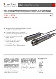
<strong>Ultrasonic</strong> <strong><strong>for</strong>k</strong> <strong>sensors</strong> <strong>for</strong> <strong>web</strong> <strong>guide</strong> <strong>and</strong> <strong>edge</strong> <strong>control</strong><br />
<strong>UPF</strong>-A <strong>Series</strong><br />
• <strong>Ultrasonic</strong> <strong><strong>for</strong>k</strong> barrier with analogue output 0...10V<br />
• The analogue signal is a function of lateral covering<br />
• For <strong>edge</strong> <strong>control</strong> <strong>and</strong> <strong>web</strong> guidance systems<br />
• For transparent foils<br />
• For contaminated air<br />
• High accuracy <strong>and</strong> temperature stability<br />
• High measurement range<br />
• Very small plane change influence<br />
• high sampling rate<br />
• teach-in<br />
• Swiss made<br />
Technical data <strong>UPF</strong>-A 30/8<br />
TOR 24 CA<br />
<strong>UPF</strong>-A 60/8<br />
TOR 24 CA<br />
<strong>UPF</strong>-A 40/13<br />
TOR 24 CA<br />
Fork width mm 30 60 40 70<br />
Detection width mm ~8 (±4) ~13 (±6.5)<br />
Resolution (noise):<br />
- @ 20...80% covered<br />
- @ 0...100% covered<br />
Plane change (influence of position between<br />
transmitter T <strong>and</strong> receiver R):<br />
- 7mm off T or R<br />
- 5mm off T or R<br />
mm<br />
mm<br />
mm<br />
mm<br />
mm<br />
mm<br />
ca. 0.1<br />
ca. 0.15<br />
≤ ±0.5<br />
≤ ±0.1<br />
≤ ±0.3<br />
≤ ±0.1<br />
Linearity @ 10...90% covered (typical) %FS ≤ 2 ≤ 4<br />
<strong>Ultrasonic</strong> frequency kHz approx. 180 approx. 130<br />
Sampling frequency (in non synchronized mode) Hz 500 285<br />
Output signal V 0...10<br />
Temperature stability 0...60°C (typical) % ±5<br />
Power supply voltage (polarity reversal protection) VDC 8...30<br />
Ripple of supply voltage % 10<br />
Current consumption @ 24VDC mA 35<br />
Power consumption W 0.9<br />
Power indicator - 3 LED yellow/green/yellow in keyboard<br />
Ambient temperature during operation °C 0...+60<br />
Storage temperature °C -10...+70<br />
Synchronization input (connector pin 2)<br />
- square wave signal (on rising <strong>edge</strong>)<br />
- min. signal duration<br />
- max. sampling frequency (<strong>for</strong> proper<br />
signal)<br />
V<br />
ms<br />
Hz<br />
3.5 ... 30<br />
0.02<br />
500<br />
Max. cable length m 20<br />
Protection class - IP67<br />
Housing material - black anodized aluminum<br />
3.5 ... 30<br />
0.02<br />
285<br />
<strong>UPF</strong>-A 70/13<br />
TOR 24 CA
SONARANGE<br />
<strong>UPF</strong>-A 03.10 e<br />
Electrical connection - M12 connector, 4-pin<br />
Mass g 200 220 360 400<br />
Properties<br />
The <strong>edge</strong> <strong>sensors</strong> type <strong>UPF</strong>-A are based on the experience<br />
of SNT Sensortechnik AG with ultrasonic through beam<br />
<strong>sensors</strong>. New software algorithms <strong>and</strong> a unique SONARANGE<br />
ultrasonic transducer material allow an accuracy <strong>and</strong><br />
temperature stability so far only realized with optical systems.<br />
But the ultrasonic <strong><strong>for</strong>k</strong> barrier is much less sensitive to dirt<br />
<strong>and</strong> dust compared to optical <strong>sensors</strong>. Further more<br />
transparent materials such as foils can be perfectly h<strong>and</strong>led.<br />
0V (or 10V inverted)<br />
10V (or 0V inverted)<br />
The 5 advantages of SNT ultrasonic <strong><strong>for</strong>k</strong> <strong>sensors</strong><br />
1. The SNT ultrasonic transducers have a large<br />
diameter.<br />
Result: large measurement range combined with<br />
high linearity <strong>and</strong> resolution.<br />
2. The all new SONARANGE material of the ultrasonic<br />
transducers has a Young’s modulus which is<br />
constant up to higher temperatures compared to<br />
the past.<br />
Result: high temperature stability.<br />
3. The signals are compensated with computed data<br />
as well as with a temperature sensor.<br />
Result: precise operation up to 60°C.<br />
4. The <strong>sensors</strong> have the teach-in feature.<br />
Result: They can be adapted to the actual air<br />
condition <strong>and</strong> the material.<br />
5. Software <strong>and</strong> transducers are designed to<br />
eliminate the influence of multiple echoes.<br />
Result: Very small influence of plane change <strong>and</strong><br />
high measuring speed.<br />
The <strong>UPF</strong>-A are ultrasonic through beam <strong>sensors</strong> with<br />
separated transmitter <strong>and</strong> receiver. They are suited <strong>for</strong> <strong>edge</strong><br />
detection on <strong>web</strong> guiding systems. In contrast to<br />
conventional barriers they do not offer a simple on/off output<br />
signal, but they measure the degree of covering of the<br />
ultrasonic receiver as an analogue output signal. If the<br />
receiver is fully covered, the output is 0V <strong>and</strong> if not covered<br />
at all 10V or vice versa.<br />
The relative humidity of air <strong>and</strong> the air pressure as well (sea<br />
level) have an influence on the output signal due to physical<br />
laws (attenuation of sound). Higher air humidity or<br />
decreasing air pressure do reduce the output signal at a<br />
given <strong>edge</strong> position.<br />
• Sea level: <strong>for</strong> 100m higher sea level approx. 1.6% signal<br />
reduction<br />
• Air pressure: <strong>for</strong> 10mbar pressure increase approx.<br />
1.3% signal increase<br />
• Air humidity: <strong>for</strong> 10% higher rel. air humidity approx.<br />
1.2% signal reduction<br />
The sensor can ideally be adjusted to the actual air<br />
conditions by the help of the teach-in function.<br />
Teach-In<br />
With teach-in the signal output can be defined at fully closed<br />
<strong><strong>for</strong>k</strong> (status A) as well as at fully open <strong><strong>for</strong>k</strong> (status B).<br />
• Status A: If an acoustically non transparent material is in<br />
the <strong><strong>for</strong>k</strong>, no signal is recorded by the receiver <strong>and</strong> thus<br />
the sensor shows 0V. However if the material is partly<br />
acoustically transparent (e.g. textiles), the sensor would<br />
show an offset. By teaching this status the offset can be<br />
eliminated <strong>and</strong> the full 10V span is available. For<br />
teaching the status A the material must be fully<br />
introduced into the <strong><strong>for</strong>k</strong>.<br />
• Status B: If nothing is between transmitter <strong>and</strong> receiver,<br />
the sensor should show the full signal of 10V. As<br />
explained above, the signal can slightly vary depending<br />
on air conditions. By teaching this status the full range<br />
signal can be adjusted to exactly 10V. For teaching the<br />
status B the <strong><strong>for</strong>k</strong> must be fully free of material.<br />
In addition, the output signal can also be inverted via teachin,<br />
i.e. either rising or falling signal with increasing coverage<br />
of the sensor.
SONARANGE<br />
<strong>UPF</strong>-A 03.10 e<br />
Teach-In with keyboard<br />
• Status A (material is fully introduced): push key A <strong>for</strong><br />
min. 2s until yellow LED near A blinks 3x<br />
(acknowledgment by lighting of all 3 LEDs)<br />
• Status B (no material in <strong><strong>for</strong>k</strong>): push key B <strong>for</strong> min. 2s<br />
until yellow LED near B blinks 3x (acknowledgment by<br />
lighting of all 3 LEDs)<br />
• Inverting the signal: push both keys A <strong>and</strong> B<br />
simultaneously <strong>for</strong> min. 5s until yellow LED near A lights<br />
up. Then release keys. Acknowledgment by lighting of<br />
all 3 LEDs. Reverse the inverting by the same<br />
procedure.<br />
• Factory reset: push both keys A <strong>and</strong> B simultaneously<br />
<strong>for</strong> 10s until green LED lights up. Then release keys.<br />
Acknowledgment by lighting of all 3 LEDs.<br />
• Key lock: push both keys A <strong>and</strong> B simultaneously <strong>for</strong><br />
15s until yellow LED near B lights up. Then release<br />
keys. Acknowledgment by lighting of all 3 LEDs. Unlock<br />
the keys in the same way.<br />
Application<br />
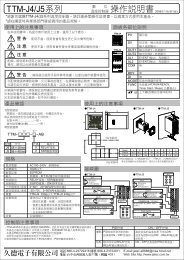
Measurement of the <strong>web</strong> <strong>edge</strong> position:<br />
Various <strong><strong>for</strong>k</strong> widths:<br />
Teach-In by the connector<br />
Pin 4 of the connector has besides the function <strong>for</strong><br />
synchronization also the same teach function as Key B. The<br />
adjustment of the max. signal output at fully open <strong><strong>for</strong>k</strong> can<br />
there<strong>for</strong>e also be done by connecting pin 4 with power supply<br />
voltage (nom. 24VDC) during min. 2s. Subsequently, the pin<br />
4 must be removed from the tension.<br />
The sensor can e.g. be operated after teaching with a 3 wire<br />
cable as well. Teach via connector is possible also if the key<br />
lock is enabled.<br />
Larger <strong><strong>for</strong>k</strong> widths are of particular interest if the material <strong>web</strong><br />
is vertically heavily flattering or if it does not always pass at<br />
the same position during unroll or roll up (see picture below).<br />
Synchronization<br />
The internal sampling clock of the sensor can be overcome<br />
with an external repeating signal. This can be helpful if<br />
several <strong>sensors</strong> are measuring along a fast moving <strong>web</strong>.
SONARANGE<br />
<strong>UPF</strong>-A 03.10 e<br />
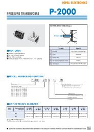
Dimensions<br />
52<br />
Electrical connection<br />
4<br />
M4<br />
1<br />
3<br />
92 / 122<br />
7<br />
40 / 70<br />
54<br />
54 / 84<br />
2<br />
View on the sensor<br />
22.5<br />
M4<br />
20<br />
1 brown: +24VDC<br />
2 white: synchronization / teach-in input<br />
3 blue: 0V<br />
4 black: analogue output 0...10V<br />
Accessories (see also data sheet ‚ACC’)<br />
39<br />
PUR cable 3-wire (pin 1, 3, 4) with M12 connector:<br />
l=2m Type KAB 2L3VGPUR<br />
80<br />
PUR cable 4-wire with M12 connector:<br />
l=2m Type KAB 2L4VGPUR<br />
<strong>UPF</strong>-A 40/13 TOR 24 CA / <strong>UPF</strong>-A 70/13 TOR 24 CA<br />
38<br />
M4<br />
30 / 60<br />
74 / 104<br />
5<br />
40 / 70<br />
40<br />
M4<br />
15<br />
15<br />
30<br />
65<br />
<strong>UPF</strong>-A 30/8 TOR 24 CA / <strong>UPF</strong>-A 60/8 TOR 24 CA