VLBG< - RUD
VLBG< - RUD
VLBG< - RUD

Create successful ePaper yourself
Turn your PDF publications into a flip-book with our unique Google optimized e-Paper software.
<strong>RUD</strong>-Art.-Nr.: 8500972-EN / 11.013<br />
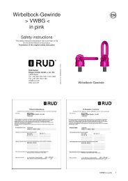
Load Ring for bolting<br />
>VLBG<<br />
EN<br />
Safety instructions<br />
This safety instruction/declaration of the manufacturer has to be<br />
kept on file for the whole lifetime of the product.<br />
Translation of the original instructions<br />
<strong>RUD</strong> Ketten<br />
Rieger & Dietz GmbH u. Co. KG<br />
73428 Aalen<br />
Tel. +49 7361 504-1351-1370-1262<br />
Fax +49 7361 504-1460<br />
info@rud.com<br />
www.rud.com<br />
Load Ring in pink - for bolting<br />
VLBG<br />
VLBG<br />
1
Please read user instruction before initial<br />
operation of the bolt-on lifting point VLBG.<br />
Make sure that you have comprehend all<br />
subjected matters.<br />
Non observance can lead to serious personal<br />
injuries and material damage and<br />
eliminates warranty.<br />
1 Safety instructions<br />
ATTENTION<br />
Wrong assembled or damaged VLBG as<br />
well as improper use can lead to injuries of<br />
persons and damage of objects when load<br />
drops.<br />
Please inspect all VLBG before each use.<br />
• Reference should be made to German Standards<br />
accord. BGR 500 or other country specific statutory<br />
regulations and inspections are to be carried out<br />
by competent persons only.<br />
• When using your own bolts, the bolts have to be<br />
100 % crack tested.<br />
• The VLBG must be rotatable 360° when installed.<br />
2 Intended use<br />
VLBGs must only be used for the assembly of the<br />
load or at load accepting means<br />
Their usage is intended to be used as lifting means.<br />
The VLBGs can also be used as lashing points for<br />
the fixture of lashing means.<br />
The VLBGs must only be used in the here described<br />
usage purpose.<br />
3 Assembly- and instruction manual<br />
3.1 General information<br />
• Effects of temperature:<br />
Due to the DIN/EN bolts that are used in the VLBG,<br />
the working load limit must be reduced accordingly:<br />
-40°C to 100°C --> no reduction (-40°F to 212°F)<br />
100°C to 200°C minus 15 % (212°F to 392°F)<br />
200°C to 250°C minus 20 % (392°F to 482°F)<br />
250°C to 350°C minus 25 % (482°F to 662°F)<br />
Temperatures above 350°C (662°F) are not<br />
permitted.<br />
Please observe the maximum usage temperature<br />
of the supplied nuts (optionally):<br />
• Clamping nuts according to DIN EN ISO 7042<br />
(DIN 980) must only be used up to +150°C at<br />
the max (302°F).<br />
• Collar nuts according to DIN 6331 can be used<br />
up to +300°C. Please note also the reduction<br />
factors (572°F).<br />
• <strong>RUD</strong>-Lifting points must not be used under chemical<br />
influences such as acids, alkaline solutions and<br />
vapours e.g. in pickling baths or hot dip galvanising<br />
plants. If this cannot avoided, please contact the<br />
manufacturer indicating the concentration, period<br />
of penetration and temperature of use.<br />
• The places where the lifting points are fixed should<br />
be marked with colour.<br />
• <strong>RUD</strong> lifting points are delivered with a 100 % crack<br />
tested bolt (length up to lmax please see chart 3).<br />
When using your own bolts, the bolts have to be<br />
100 % crack tested.<br />
Versions<br />
HINT<br />
The min. quality of the hexagon bolt has to<br />
be 10.9 accord. EN 24014 (DIN 931) with<br />
the nominal diameter. For replacement the<br />
bolt can be easily hammered out.<br />
• The type VLBG 7 t M36 is only delivered with a<br />
special bolt, therefore it is not possible to use<br />
a DIN/EN-bolt.<br />
• <strong>RUD</strong> supplies the Vario length complete with a<br />
washer and crack-detected nut corresponding<br />
to DIN EN ISO 7042 (DIN 980) or will be<br />
supplied with a crack inspected collar nut acc.<br />
to DIN 6331.<br />
• If the VLBG is used exclusively for lashing, the value<br />
of the working load limit can be doubled.<br />
LC = permissible lashing capacity = 2 x WLL<br />
3.2 Hints for the assembly<br />
Basically essential:<br />
• The material construction to which the lifting point<br />
will be attached should be of adequate strength to<br />
withstand forces during lifting without deformation.<br />
The German testing authority BG, recommends the<br />
following minimum for bolt lengths:<br />
1 x M in steel (minimum quality S235JR<br />
[1.0037])<br />
1,25x M in cast iron (for example GG 25)<br />
2 x M in aluminium alloys<br />
2,5 x M in aluminium-magnesium alloys<br />
(M = diameter of <strong>RUD</strong> lifting point bolt, for ex. M 20)<br />
• When lifting light metals, nonferrous heavy metals<br />
and gray cast iron the thread has to be chosen in<br />
such a way that the working load limit of the thread<br />
corresponds to the requirements of the respective<br />
base material.<br />
2 VLBG
• The lifting points must be positioned on the load in<br />
such a way that movement is avoided during lifting:<br />
• For single leg lifts, the load ring should be<br />
positioned vertically above the centre of<br />
gravity of the load.<br />
• For two leg lifts, the lifting points must be<br />
equidistant to/or above the centre of gravity<br />
of the load.<br />
• For three and four leg lifts, the lifting points<br />
should be arranged symmetrically around the<br />
centre of gravity in the same plane, if<br />
possible.<br />
• Load symmetry:<br />
The working load limit of individual <strong>RUD</strong> lifting<br />
points are calculated using the following formula<br />
and are based on symmetrical loading:<br />
W LL<br />
=<br />
G<br />
n x cos ß<br />
W LL<br />
G<br />
n<br />
ß<br />
= working load limit<br />
= load weight (kg)<br />
= number of load bearing legs<br />
= angle of inclination of the chain to the vertical<br />
The calculation of load bearing legs is as follows:<br />
symmetrical asymmetrical<br />
two leg 2 1<br />
three / four leg 3 1<br />
table 1: Load bearing strands (see table 2)<br />
HINT<br />
With unsymmetrical loads, the WLL of each<br />
Lifting Point must be at least as high as the<br />
weight of the load.<br />
• A Plane bolting surface (ØDB, table 3) with a<br />
rectangular machined thread hole must be<br />
guaranteed.<br />
• The holes must be drilled with a sufficient depth in<br />
order to guarantee compatibility with the supporting<br />
surface.<br />
• The VLBG must be rotatable 360° when installed.<br />
Please observe the following:<br />
• For a single use hand tightening with a spanner<br />
is sufficiant. Bolt supporting area must sit proper<br />
on bolt-on surface.<br />
• For long term application the VLBG must be<br />
tightened with torque according to table 3<br />
(+/- 10 %).<br />
• When turning loads using the VLBG (see<br />
chapter 3.3.2 permissible lifting- and turning<br />
process) it is necessary to tighten the bolt with<br />
a torque (+/- 10 %) acc. to chart 3.<br />
• With shock loading or vibrations, especially at<br />
through hole fixtures with a nut at the end of the<br />
bolt, accidential release can occure.<br />
Securing possibilities: Observe torque moment,<br />
use liquid securing glue f.e. Loctite (can be adapted<br />
to the usage, observe manufacturer hints) or<br />
assemble a form closure bolt locking device f.e. a<br />
castle nut with cotter pin, locknut etc.<br />
• Finally check the proper assembly (see chapter 4<br />
Inspection criteria).<br />
3.3 User instructions<br />
3.3.1 General information for the usage<br />
• Before every usage, control in regularly periods the<br />
whole lifting point in regard of the continuous<br />
aptitude as a lifting mean, whether it is tightened<br />
(torqued), or has strong corrosion, wear,<br />
deformations etc. (see chapter 4 Inspection criteria).<br />
ATTENTION<br />
Wrong assembled or damaged VLBG as<br />
well as improper use can lead to injuries of<br />
persons and damage of objects when load<br />
drops.<br />
Please inspect all VLBG before each use.<br />
• Adjust to the direction of pull, before attaching to<br />
the lifting means. The load ring should be free<br />
movable and must not touch edges.<br />
• All fittings connected to the VLBG should be free<br />
moving. When connecting and disconnecting the<br />
lifting means (sling chain) pinches and impacts<br />
should be avoided.<br />
• Damage of the lifting means caused by sharp edges<br />
should be avoided as well.<br />
VLBG<br />
3
3.3.2 Allowed lifting and turning operations<br />
F<br />
Pic. 2: Pivoting in load direction<br />
• Turning operations where the VLBG will be turned<br />
around the bolt axle (exception: see chapter 3.3.3<br />
Forbidden lifting and turning operations).<br />
After a full turn by 180° the torque of the bolt must<br />
be checked.<br />
WARNING<br />
Observe the requested torque value before<br />
each lifting or turning operation.<br />
3.3.3 Forbidden lifting and turning operations<br />
The following operations are forbidden:<br />
WARNING<br />
The turning of the VLBG under load in the<br />
direction of the bolt axle (+15°) is forbidden.<br />
F<br />
15°<br />
Pic. 1: Possible turning operation with the VLBG<br />
Pic. 3: Forbidden turning<br />
direction at loading in the<br />
direction of the axle.<br />
The following turning operations are allowed<br />
• Turning operations where the load ring will be<br />
turned into the load direction<br />
WARNING<br />
The load ring must not support itself at<br />
edges or other attachments.<br />
Also the attached lifting mean must not<br />
touch the head oft he bolt.<br />
3.4 Hints for periodical inspections<br />
Have VLBG checked by a competent person in periods<br />
which are determined by the usage, but at least 1x per<br />
year, in regard of the ongoing appropriateness of the<br />
lifting point (see chapter 4 Inspection criteria).<br />
Depending on the usage conditions, f.e. frequent<br />
usage, increased wear or corrosion, it might be<br />
necessary to check in shorter periods than one year.<br />
The inspection has also to be carried out after accidents<br />
and special incidents.<br />
4 VLBG
Method of lift<br />
Number of legs 1 1 2 2 2 2 2 3 & 4 3 & 4 3 & 4<br />
Angle of inclination control of the torque<br />
• The lifting point should be complete.<br />
• The working load limit and manufacturers stamp<br />
should be clearly visible.<br />
• Deformation of the component parts such as body,<br />
load ring and bolt.<br />
• Mechanical damage, such as notches, particularly<br />
in high stress areas.<br />
• Wear should be not more than 10 % of cross<br />
sectional diameter.<br />
• Evidence of corrosion.<br />
• Evidence of cracks.<br />
• Damage at the bolt, nut and/or thread.<br />
• The body of the VLBG must be free to rotate.<br />
VLBG<br />
5
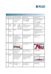
Type WLL weight A B C D E F G H H J K L L M N SW R T DB torque Ref.-No.<br />
[t] [kg] Stand. max. Stand. max. Standard Vario<br />
VLBG 0.3 t M8 0.3 0.3 30 54 34 35 40 10 29 11 76 75 45 40 105 8 5 13 32 75 24 30 Nm 8500821 8600280<br />
VLBG 0.63 tM10 0.63 0.32 30 54 34 36 39 10 29 16 96 75 45 45 125 10 6 17 32 75 24 60 Nm 8500822 8600281<br />
VLBG 1 t M12 1 0.33 32 54 34 37 38 10 29 21 116 75 45 50 145 12 8 19 32 75 26 100 Nm 8500823 8600382<br />
VLBG 1.2 t M14 1.2 0.55 33 56 36 46 39 13.5 36 34 86 47 70 16 10 24 38 85 30 120 Nm - 8600399<br />
VLBG 1.5 t M16 1.5 0.55 33 56 36 46 39 13.5 36 24 149 86 47 60 185 16 10 24 38 85 30 150 Nm 8500824 8600383<br />
VLBG 2.0 t M18 2 1.3 50 82 54 55 55 16.5 43 47 113 64 90 18 12 30 48 110 45 200 Nm - 8600384<br />
VLBG 2.5 t M20 2.5 1.3 50 82 54 55 55 16.5 43 32 187 113 64 75 230 20 12 30 48 110 45 250 Nm 8500826 8600385<br />
VLBG 4 t M24 4 1.5 50 82 54 58 67 18 43 37 222 130 78 80 265 24 14 36 48 125 45 400 Nm 8500827 8600386<br />
VLBG 4 t M27 4 3.1 60 103 65 78 69 22.5 61 39 - 151 80 100 - 27 - 41 67 147 60 400 Nm 7983658 -<br />
VLBG 5 t M30 5 3.3 60 103 65 80 67 22.5 61 49 279 151 80 110 340 30 17 46 67 147 60 500 Nm 8500828 8600388<br />
VLBG 7 t M36 7 3.4 60 103 65 72 74 22.5 55 52 - 151 80 107 - 36 - 55 67 146 60 700 Nm 8500829 -<br />
VLBG 8 t M36 8 6.2 77 122 82 100 97 26.5 77 63 223 205 110 140 300 36 22 55 87 197 70 800 Nm 7983553 8600289<br />
VLBG 10 t M42 10 6.7 77 122 82 103 94 26.5 77 73 273 205 110 150 350 42 24 65 87 197 70 1000 Nm 7983554 8600290<br />
VLBG 15 t M42 15 11.2 95 156 100 113 109 36 87 63 263 230 130 150 350 42 24 65 100 222 85 1500 Nm 7982966 8600291<br />
VLBG 20 t M48 20 11.6 95 156 100 117 105 36 87 73 303 230 130 160 390 48 27 75 100 222 95 2000 Nm 7982967 8600292<br />
LBG (3) M16 RS 1 t 1 1 50 85 50 45 43 16.5 38 25 - 95 45 63 - 16 - 24 46 88 40 100 Nm 62086<br />
LBG (3) M20 RS 2 t 2 1.1 50 85 50 46 42 16.5 38 27 - 95 45 65 - 20 - 30 46 88 40 200 Nm 62813<br />
Attention: the stainless load ring is not suitable for use in chloride media (e.g. indoor swimming-pools)<br />
VLBG-Z 0.63 t 0.63 0.32 30 54 34 36 39 10 29 16 96 75 45 45 125 3/8" 1/4" 9/16" 32 75 24 60 Nm 8504256 8600440<br />
3/8"-16 UNC<br />
VLBG-Z 1 t 1 0.33 32 54 34 38 37 10 29 22 121 75 45 50 150 1/2" 5/16" 3/4" 32 75 26 100 Nm 8502349 8600441<br />
1/2"-13 UNC<br />
VLBG-Z 1.5 t 1.5 0.55 33 56 36 46 38 13.5 36 24 148 87 47 60 184 5/8" 3/8" 15/16" 38 85 30 150 Nm 8502350 8600442<br />
5/8"-11UNC<br />
LBG-Z 2.5 t 2.5 1.3 50 82 54 56 54 16.5 43 28 187 113 64 71 230 3/4" 1/2" 1 1/8" 48 110 45 250 Nm 8502351 8600443<br />
3/4"-10UNC<br />
VLBG-Z 2.5 t 2.5 1.3 50 82 54 58 52 16.5 43 27 211 113 64 70 254 7/8" 1/2" 1 5/16" 48 110 45 300 Nm 8502352 8600444<br />
7/8"-9 UNC<br />
VLBG-Z 4 t 4 1.5 50 82 54 61 64 18 43 41 211 130 78 84 254 1" 9/16" 1 1/2" 48 125 45 400 Nm 8502353 8600445<br />
1"-8 UNC<br />
VLBG-Z 5 t 5 3.3 60 103 65 80 64 22.5 61 41 279 151 80 102 340 1 1/4" 5/8" 1 7/8" 67 147 60 500 Nm 8503187 8600446<br />
11/4"-7 UNC<br />
VLBG-Z 8 t 8 6.2 77 122 82 100 97 26.5 77 62 270 205 110 139 347 1 1/2" 7/8" 2 1/4" 87 197 70 800 Nm 8504257 8600447<br />
1 1/2"-6 UNC<br />
VLBG-Z 20 t 20 11.6 95 156 100 117 105 36 87 69 303 230 130 156 390 2" 1 1/8" 3" 100 222 95 2000 Nm 8504258 8600448<br />
2"-4 1/2 UNC<br />
table 3: Dimensioning Subject to technical modifications<br />
<strong>RUD</strong> components are designed for a dynamical loading<br />
of 20 000 load cycles at nominal working load.<br />
6 VLBG<br />
The BG recommends: At a high dynamic loading with<br />
high numbers of load cycles (continious work) the<br />
bearing stress acc. to FEM group 1B m<br />
(M3 acc. to DIN<br />
818-7) must be reduced.