Technical handbook
Technical handbook
Technical handbook

Create successful ePaper yourself
Turn your PDF publications into a flip-book with our unique Google optimized e-Paper software.
FOUR NOZZLES<br />
VACUUM FILLING MACHINE<br />
<br />
<br />
<br />
<br />
TENCO s.r.l.<br />
Via Arbora 1<br />
16030 Avegno (GE) Italia<br />
tel +39-0185-79556 - fax +39-0185-79412<br />
ww.tenco.it - info@tenco.it<br />
<strong>Technical</strong> <strong>handbook</strong>
SUMMARY<br />
<br />
EC Declaration of Conformity pag.3<br />
1 GENERAL DIRECTIONS AND INSTRUCTIONS pag.4<br />
1.1 Foreward pag.4<br />
1.2 Description of equipment pag.4<br />
1.3 Use pag.4<br />
1.4 <strong>Technical</strong>e Features pag.4<br />
1.5 Customer's responsibility pag.4<br />
1.6 Connection and start-up pag.4<br />
1.7 Safety instructions pag.4<br />
1.8 Direction for use pag.4<br />
1.8.1. Start-up pag.4<br />
1.8.2. Stopping and emergency procedures pag.4<br />
2 INSTALLATION AND DIRECTIONS FOR USE pag.5<br />
Drawings<br />
pag.6<br />
3 CLEANING AND MAINTENANCE pag.7<br />
4 DIAGNOSTIC pag.7<br />
4.1. Possible troubles while Enolmaster running pag.7<br />
4.2 Troubleshooting pag.7<br />
5 REFERENCE STANDARDS pag.8<br />
6 WARRANTY pag.8<br />
MIGNON SET INSTALLATION<br />
MOTOR FILTER INSTALLATION<br />
SPARE PARTS - DRAWING<br />
pag.9<br />
pag.10<br />
pag.11
EC DECLARATION OF CONFORMITY<br />
<br />
The undersigned:<br />
TENCO s.r.l.<br />
Via Arbora 1 -16030 Avegno (GE) Italy-<br />
Declares, on its own responsibility, that the new machine<br />
Mod. ENOLMASTER<br />
Serial number<br />
Building year 2008<br />
described here below: "vacuum filling machine 4 nozzles"<br />
complies with the European Regulations about Safety of home equipment EUROPEAN<br />
REGULATION EN 60335-1<br />
Name: Giuseppe Tenco<br />
Position: Sole Director<br />
Place and date : Avegno,.<br />
Signature:
CHAPTER 1 - GENERAL DIRECTIONS AND INSTRUCTIONS<br />
<br />
1.1 FOREWARD<br />
Before using Enolmaster, carefully read these directions for use, using the table enclosed. Make sure that<br />
voltage shown on the data plate -to be found on the bottom- corresponds to your home supply.<br />
1.2 DESCRIPTION OF EQUIPMENT<br />
Enolmaster is a professional vacuum filling machine for the filling of approx. 600 bottles/hour.<br />
1.3 USE<br />
This equipment is to be used with wine, oil, tomato sauce, spirits, fruit juices and thick products.<br />
NOTE: Products with more than 20% alcohol content could damage Enolmaster.<br />
Therefore, in this case, we recommend to request the model P9921 (equipped with pyrex recovery vessel).<br />
In case the machine is used with the filter, please request TANDEM PROFESSIONAL mod. P9915 (equipped<br />
with pyrex filter holder).<br />
Also, if Enolmaster is employed to fill sugary liquors or products like balsamic vinegar, the oil-filled air filter<br />
must be employed to avoid damage to the machine vacuum pump; this accessory is not part of the standard<br />
supply and, if necessary, it must be ordered directly from the manufacturer.<br />
Tenco s.n.c. shall not be held responsible in case of malfunctioning of Enolmaster when the machine is<br />
operated to fill products as those described above, without using the above specified accessories.<br />
1.4 TECHNICAL FEATURES<br />
Refer to the label on the machine.<br />
1.5 CUSTOMER'S RESPONSIBILITY<br />
Installation of filling machines in premises complying with all applicable sanitary regulations and fitted with<br />
certified electrical systems shall be responsibility of the user.<br />
1.6 CONNECTION AND START-UP<br />
Place the equipment on a suitable surface. Ensure the main switch is on OFF position and connect power<br />
cable.<br />
1.7 SAFETY INSTRUCTIONS<br />
Do not spill liquids into slots.<br />
Do not open the machine, and, if so, only after power disconnection<br />
1.8 DIRECTIONS FOR USE<br />
1.8.1. Start-up: this equipment is started by acting on the relevant control or main switch.<br />
1.8.2. Stopping and emergency procedures: emergency stop is activated by sectioning the mains<br />
through electrical plug removal.<br />
IMPORTANT: if you switch engine off while using Enolmaster, it’s absolutely necessary, before switching it on<br />
again, to raise knob “S” until there is no vacuum. The same operation must be performed to remove the bowl<br />
cover.
CHAPTER 2 - INSTALLATION AND DIRECTIONS FOR USE<br />
<br />
1. Before using Enolmaster, carefully read these directions for use, using the table enclosed. Make sure that<br />
voltage shown on the data plate -to be found on the bottom- corresponds to your home supply.<br />
2. Place Enolmaster on the work table.<br />
<br />
3. Assemble the overflow float (fig. 1) by placing the “S” knob with ists gasket into the proper hole at the<br />
centre of the vessel cover. Then place the float under the cover while slightly pressing the tapered plug of<br />
the knob into the proper float housing.<br />
<br />
4. Connect transparent hoses “B” to fittings “B” on the cover of bowl and black hose “A” to fitting “A” on bowl<br />
cover (fig. 2).<br />
<br />
5. Connect the manifold from nozzles “C” with the rigid suction pipe by using the 2 m transparent pipe<br />
supplied with the unit. The “Z” end side (suction control) must be set to allow for fluid flow (fig. 3).<br />
<br />
6. Connect the pipes of manifold ( C) to the nozzles.<br />
7. Connect the power cable by plugging in the plug into the Enolmaster socket and switch Enolmaster on by<br />
pressing switch “F” (fig. 4).<br />
8. Place the suction pipe into the demijohn (or container). Be sure not to place the “Z” end in a way lees or<br />
sediments may be sucked in.<br />
9. Place the bottles on the proper base and one after the other into the nozzles. When the bottle is properly<br />
placed, the lever “H” should be in horizontal position (fig. 5). To properly adjust the lever, adjust the height<br />
of the nozzle-holding shaft “K” and lock it with the knob “X”.<br />
10. To adjust the filling level in the bottle, act on the “N” nut of the nozzle. The maximum filling is obtained by<br />
pulling downwards the “Q” check nut while turning the “N” nut until the “R” position is reached. The<br />
minimum filling is obtained by leaving the nut in “P” position. Intermediate filling levels are obtained by<br />
positioning the nut in between “P” and “R” positions.<br />
WARNING: to mantain a constantly precise filling, after Enolmaster has filled the bottles and the foam<br />
eliminated, rapidly remove the bottles out of the nozzles.<br />
Important: if you switch engine off while using Enolmaster, it’s absolutely necessary, before switching it on<br />
again, to raise knob “S” until there is no vacuum. The same operation must be performed to remove the<br />
bowl cover.<br />
11. Filling speed may be adjusted by turning the vacuum knob (fig. 8). When using Enolmaster to fill thick fluids<br />
(oil, tomato sauce, a.s.o.) turn the knob to maximum position. Conversely, when filling sparkling wines,<br />
beer, a.s.o., turn the knob to minimum. Excessively high filling speed may cause too much foam.<br />
12. In order to empty the recovery tank without removing it from its housing, lift the “S” knob of the float (fig. 7)<br />
until you have no more vacuum inside. Then raise the lid and open the appropriate emptying tap.
CHAPTER 3 - CLEANING AND MAINTENANCE<br />
<br />
No maintenance is required, except for cleaning and sanitizing before and after use.<br />
In order to clean equipment, after rising, isolate the equipment by sectioning power supply.<br />
The recovery tank can be washed with water alone or, in case oil was bottled, with dishwashing liquid.<br />
When handling different products, kits supplied by Tenco s.n.c. (Oil kit, Jar kit, Tomato kit, ecc.) are<br />
recommended.<br />
To replace the nozzles, rotate the “T” handle by half turn and remove the “U” pin (fig. 9). Open the two plastic<br />
elements of the lever and disconnect the entire assembly fron the rod. Then disengage the spring. To install<br />
others nozzles, follow the above instructions in the opposite way.<br />
CHAPTER 4 - DIAGNOSTICS<br />
4.1 POSSIBLE TROUBLES WHILE ENOLMASTER IS RUNNING<br />
In case of malfuncioning and/or breakdown/failure, set the main switch on OFF and immediately unplug the<br />
unit.<br />
Any operation on electrical parts inside the case shall be performed by authorised and specifically trained<br />
personnel. Warning: hazardous voltage can harm you during maintenance on energised apparatus.<br />
Warning: any operation on equipment shal be performed after releasing any remaining pressure and<br />
disconnecting from mains (see chap. 2- point 9).<br />
If things go wrong, check the table below. If none of the solutions listed gives a positive result, get in touch with<br />
our authorized retailer.<br />
4.2 TROUBLESHOOTING<br />
Troubles Causes Solutions<br />
Engine doesn’t start 1) no electricity supply<br />
2) plug not connected<br />
1) check<br />
2) check<br />
3) the fuses of the power socket may 3) disconnect the power cable and remove<br />
have burnt out (fig. 4)<br />
4) the whole device is in a vacuum<br />
them by unscrewing the fuse block in the<br />
socket by one quarter of turn. Check the<br />
fuse conditions and if necessary replace<br />
them (1,6 A 250 V)<br />
4) raise knob “S” of the float for few seconds<br />
(fig. 7)<br />
Liquid doesn’t go<br />
into the bottle<br />
1) engine off<br />
2) the bowl cover is improperly closed<br />
3) the speed adjuster is improperly<br />
set to minimum<br />
4) the nozzles are clogged<br />
5) the suction pipe is resting on the<br />
demijohn bottom<br />
6) the bottle mouth edge is chipped<br />
7) the rubber ring of the closing cone<br />
is broken<br />
8) the nozzles fail to slide properly<br />
1) check<br />
2) close it well by pushing downwards<br />
3) turn the knob clocwise to maximum (fig. 8)<br />
4) check whether the “A” suction hole is<br />
obstructed. Blow into the nozzle from the<br />
side of the “B” foam recovery hose, while<br />
raising the “E” closing cone. Further check<br />
that the “C” fluid outflow hole is not clogged<br />
by blowing from the side of the “D” suction<br />
pipe, while still raising the “E” closing cone.<br />
(fig. 13)<br />
5) adjust the “Z” end side to mantain the<br />
suction pipe at a certain distance from the<br />
bottom<br />
6) replace the bottle<br />
7) replace it<br />
8) check the 2.02 and 2.06 o-rings. (see<br />
exploded drawing). Grease nozzles with<br />
vaseline oil (see 4.03 on the exploded<br />
drawing)
!<br />
<br />
<br />
CHAPTER 5 - REFERENCE STANDARDS<br />
<br />
Statutory regulations<br />
- Decree Law n° 615, dd. 12/11/1996 - Transposition of the Community Directive n° 89/336/EEC on<br />
Electromagnetic Compatibility (EMC).<br />
- Law n° 791, dd. 18/10/1977 - Transposition of the Community Directive (DB) (73/23/EEC) on electrical<br />
equipment safety assurance.<br />
- Decree Law n° 626, dd. 25/11/1996 - Transposition of the directive 93/68/EEC on CE marking for electrical<br />
equipment to be used within specific voltage ranges.<br />
Voluntary regulations<br />
- EN 60335-1 (1989 - Safety on household elecrical appliances and similar appliances.<br />
- General provisions (IEC 335-1/1/1976).<br />
- European Directive on Electromagnetical Compatibility n° 89/336/EMC<br />
CHAPTER 6 - WARRANTY<br />
The Manufacturer guarantees that the equipment to which these documents refer has been tested and that the<br />
established test results have been achieved.<br />
The warranty period shall last 12 months, beginning on the date of delivery of the equipment (as indicated in<br />
the transport document), except as otherwise agreed upon between the Parties.<br />
The Manufacturer guarantees the equipment to be free from defects in materials and workmanship. Damage<br />
deriving from transport not carried out by transport means of the Manufacturer, from improper maintenance,<br />
failure of electrical equipment, improper use or negligence, or adjustments/repairs carried out by service<br />
personnel not duly authorized by the Manufacturer or in any case beyond the control of the Manufacturer shall<br />
NOT be covered by this warranty.<br />
The warranty cannot be transferred by the initial owner of the product to third parties.<br />
During the applicable warranty period, the Manufacturer will repair or replace free of charge any warranted<br />
parts that prove defective. For these operations to be carried out, the equipment shall have to be transported to<br />
the Manufacturer, who shall not be responsible for any transport charges.<br />
The Manufacturer shall not repair the equipment during the warranty period at the Customer's premises, except<br />
as otherwise agreed upon between the Parties.<br />
After the above specified period, this warrantee shall expire<br />
The Manufacturer shall in no event be liable for any direct, consequential, incidental, indirect or special<br />
damages caused to people or property by original defects of the equipment, equipment failure, or subsequent<br />
forced stoppage in the use of the equipment.<br />
The Manufacturer shall not be liable for filling defects if, at the time of equipment construction, the Client has<br />
failed to provide a full sampling of containers and products required in order to carry out the necessary tests.<br />
!
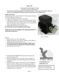
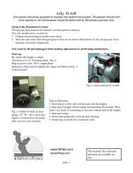
MIGNON SET – INSTALLATION<br />
<br />
1) Unscrew and remove screws C e D<br />
2) Plug in the two pins supplied with the kit into the screw housings, with their larger end turned downward.<br />
Plug them in by half their length.<br />
3) Connect the mignon manifold to the pins, through the proper housings on the manifold. Place the manifold<br />
so that the suction pipe hose adapter is on the left.<br />
4) Put the frame and the support for mignon bottles in the approriate support stick.<br />
5) Connect the manifold pipes to the four hose adapters of each filler nozzle.
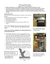
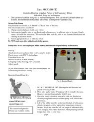
MOTOR FILTER INSTALLATION<br />
<br />
This type of filter is used when the filling machine is employed for filling fluids with a high alcohol and sugar<br />
content, such as balsamic vinegar and the whole range or products releasing vapors that could damage the<br />
Enolmaster pump.<br />
We recommend to order the filter directly from the manufacturer, if required, for it is not supplied with the filling<br />
machine. Tenco s.n.c. shall not be liable for any problems that could arise with Enolmaster operation, caused<br />
by its use without said filter when employed for the filling of products as described above.<br />
Installation:<br />
The filter must always be mounted in a vertical position. A max 30° angle is allowed.<br />
- connect the rubber junction gasket with the wording «al motore» (to motor) to rubber junction gasket «A»<br />
- connect the rubber junction gasket with the word «vaso» (tank) to rubber junction gasket «C»<br />
Note: lubricant oil for enologic use is always required. Do not allow it to exceed the level indicated in the oil<br />
sump.<br />
c<br />
MOTORE<br />
VASO<br />
Fig: 1 Fig. 2
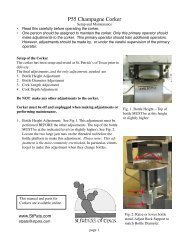
SPARE PARTS - DRAWING<br />
<br />
This manual is the property of TENCO s.r.l.. - Via Arbora 1 - 16030 Avegno (GE) Italy.<br />
Reproduction or disclosure to third party of the content of this document is forbidden.<br />
All rights are reserved.
INFORMATION FOR USERS<br />
<br />
This product is compliant with the European directive EU 2OO2/96/EC.<br />
The. crossed waste bin symbol showed on the appliance indicates that the product, by the end of its<br />
Iifetime, must be thrown out separately from usual domestic garbage, it has to be consigned to a waste<br />
differentation centre equipped for electronic and electric appliances or to the company a similar item is to be<br />
bought from.<br />
The user is responsible of the appliances consignrnent to an appropriate structure, by the end of its lifetime.<br />
The proper differentiated waste collection for the proceeding ol the treatment and the recycling o the appliance,<br />
environmentally compliant, contributes to avoiding possible negative effects on the environment and health,<br />
and favours the recycle of the compounds o the appIiance.<br />
For more detailed information regarding waste collection systems available, pIease refer to your local recycling<br />
centre, or to the appliance retailer