Motor Control PWM
Motor Control PWM
Motor Control PWM

You also want an ePaper? Increase the reach of your titles
YUMPU automatically turns print PDFs into web optimized ePapers that Google loves.
845 SNS<br />
Sensor and Sensorless <strong>Control</strong> of a<br />
BLDC <strong>Motor</strong> Using a dsPIC ® DSC<br />
Hands-on Class<br />
© 2004 Microchip Technology Incorporated. All Rights Reserved. 845 SNS Sensor and Sensorless <strong>Control</strong> of a BLDC motor using a dsPIC ® DSC 1
Agenda<br />
BLDC <strong>Motor</strong> Basics<br />
dsPIC ® DSC Peripherals for BLDC control - <strong>PWM</strong> and ADC<br />
<br />
<br />
<br />
lab 1 - “How to get started” by blinking an LED<br />
lab 2 - using the ADC<br />
lab 3 - using the <strong>PWM</strong> and multiple ADC channels<br />
<strong>Control</strong> of a BLDC motor with Position Sensors<br />
<br />
Lab 4 - Spinning a Sensored BLDC <strong>Motor</strong><br />
Review of BLDC Sensorless Techniques<br />
The Back EMF “zero crossing” technique<br />
Implementation on the dsPIC ® DSC (AN901)<br />
Commutation and other control loops<br />
<br />
Lab 5 - Setting Up and Tuning the Sensorless BLDC Reference<br />
Design<br />
© 2004 Microchip Technology Incorporated. All Rights Reserved. 845 SNS Sensor and Sensorless <strong>Control</strong> of a BLDC motor using a dsPIC ® DSC 2
Learning Objectives<br />
<br />
<br />
<br />
<br />
dsPIC ® DSC Peripherals used for BLDC<br />
<strong>Control</strong>:<br />
<br />
<br />
10-bit ADC<br />
<strong>Motor</strong> <strong>Control</strong> <strong>PWM</strong><br />
BLDC Basics<br />
BLDC <strong>Control</strong> Techniques<br />
<br />
<br />
Sensored Techniques<br />
Sensorless Techniques<br />
Write Code to Spin a Sensored and<br />
Sensorless BLDC <strong>Motor</strong><br />
© 2004 Microchip Technology Incorporated. All Rights Reserved. 845 SNS Sensor and Sensorless <strong>Control</strong> of a BLDC motor using a dsPIC ® DSC 3
BLDC <strong>Motor</strong> Basics<br />
© 2004 Microchip Technology Incorporated. All Rights Reserved. 845 SNS Sensor and Sensorless <strong>Control</strong> of a BLDC motor using a dsPIC ® DSC 4
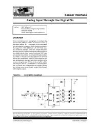
The BrushLess DC (BLDC) <strong>Motor</strong><br />
<br />
<br />
<br />
<br />
<br />
An inside out brushed DC motor with<br />
electronic commutation<br />
A modern, much improved, version of the<br />
traditional brushed DC motor.<br />
Field, which has relatively low loss, is<br />
generated on the rotor using permanent<br />
magnets.<br />
Armature, which causes the majority of the<br />
loss, is on the stator which has good<br />
cooling.<br />
The Back EMF is usually somewhere<br />
between being sinusoidal and trapezoidal.<br />
© 2004 Microchip Technology Incorporated. All Rights Reserved. 845 SNS Sensor and Sensorless <strong>Control</strong> of a BLDC motor using a dsPIC ® DSC 5
Brushed & Brushless DC <strong>Motor</strong><br />
Construction<br />
PERMANENT MAGNET BRUSHED DC<br />
MOTOR<br />
PERMANENT MAGNET BRUSHLESS<br />
DC MOTOR<br />
© 2004 Microchip Technology Incorporated. All Rights Reserved. 845 SNS Sensor and Sensorless <strong>Control</strong> of a BLDC motor using a dsPIC ® DSC 6
BLDC Advantages Over Brushed<br />
DC <strong>Motor</strong><br />
<br />
<br />
<br />
<br />
<br />
<br />
Smaller size for same power owing, mainly,<br />
to the improved cooling of the armature.<br />
Operation to higher speeds.<br />
Lower inertia as no commutator or rotor<br />
windings.<br />
Therefore much higher acceleration rates<br />
possible.<br />
No brushes to maintain.<br />
No sparking on Commutator.<br />
© 2004 Microchip Technology Incorporated. All Rights Reserved. 845 SNS Sensor and Sensorless <strong>Control</strong> of a BLDC motor using a dsPIC ® DSC 7
BLDC <strong>Control</strong><br />
<br />
<br />
<br />
<br />
Mechanical commutator of brushed motor replaced<br />
by electronic switching of the phases.<br />
Switching must be correctly synchronised to<br />
absolute rotor position to ensure smooth and<br />
efficient torque production.<br />
The BLDC is a synchronous motor with no<br />
damping or starting windings.<br />
All discussions will focus on Y connected 3 phase<br />
motors with 3 leg inverters and square wave (120°)<br />
conduction.<br />
© 2004 Microchip Technology Incorporated. All Rights Reserved. 845 SNS Sensor and Sensorless <strong>Control</strong> of a BLDC motor using a dsPIC ® DSC 8
Standard BLDC Position Sensing<br />
<br />
<br />
<br />
A sensing disk is attached to the rotor which<br />
provides a ˜ 50% duty pattern aligned to the<br />
rotor magnets. The repetition rate of the<br />
pattern will follow the number of rotor poles.<br />
The disk is monitored by three optical or hall<br />
sensors, displaced by the equivalent of<br />
120°, , located on the stator.<br />
In the case of hall sensors, the rotor<br />
magnets themselves may be sensed<br />
directly.<br />
© 2004 Microchip Technology Incorporated. All Rights Reserved. 845 SNS Sensor and Sensorless <strong>Control</strong> of a BLDC motor using a dsPIC ® DSC 9
Brushless DC <strong>Motor</strong> Construction<br />
100<br />
R<br />
R<br />
N<br />
101 b<br />
com<br />
y<br />
001<br />
S<br />
Y<br />
N<br />
S<br />
r<br />
com<br />
r<br />
S 110<br />
N<br />
N<br />
S<br />
N<br />
y<br />
B<br />
b 010<br />
B<br />
6<br />
b<br />
4<br />
r<br />
com<br />
2<br />
5<br />
1<br />
3<br />
y<br />
Y<br />
S<br />
com<br />
011<br />
© 2004 Microchip Technology Incorporated. All Rights Reserved. 845 SNS Sensor and Sensorless <strong>Control</strong> of a BLDC motor using a dsPIC ® DSC 10
Standard Sensored BLDC<br />
<strong>Control</strong><br />
The 3 logic signals are decoded to determine<br />
which windings should be energized.<br />
There are 6 valid states and 2 states that should<br />
never be seen (000, 111).<br />
Use Lookup table to drive the 3 windings, high or<br />
low or no-drive.<br />
The 6 different valid states directly translate to the<br />
6 different 60° electrical cycle sectors.<br />
The states should only transition by one at a time.<br />
Missing transitions or invalid states should be<br />
detected for robust operation.<br />
© 2004 Microchip Technology Incorporated. All Rights Reserved. 845 SNS Sensor and Sensorless <strong>Control</strong> of a BLDC motor using a dsPIC ® DSC 11
Standard BLDC <strong>Control</strong><br />
HALL A<br />
Red Winding<br />
60 o<br />
HALL B<br />
Q1<br />
Q2<br />
Q3<br />
Yellow Winding<br />
HALL C<br />
Q4<br />
R Y B<br />
Q5 Q6<br />
Blue Winding<br />
+TORQUE FIRING<br />
Q3,Q5<br />
Q1,Q5 Q1,Q6 Q2,Q6 Q2,Q4 Q3,Q4 Q3,Q5<br />
Q1,Q5<br />
Q1,Q6<br />
Sector 5<br />
0 1 2<br />
3<br />
4<br />
5<br />
0<br />
1<br />
Hall States<br />
5 4 6 2<br />
3<br />
1<br />
5<br />
4<br />
6<br />
© 2004 Microchip Technology Incorporated. All Rights Reserved. 845 SNS Sensor and Sensorless <strong>Control</strong> of a BLDC motor using a dsPIC ® DSC 12
16-bit Digital Signal <strong>Control</strong>ler<br />
Architecture<br />
© 2004 Microchip Technology Incorporated. All Rights Reserved. 845 SNS Sensor and Sensorless <strong>Control</strong> of a BLDC motor using a dsPIC ® DSC 13
dsPIC30F <strong>Control</strong>ler Family<br />
Flash Program Memory:<br />
12 K - 144 K Bytes<br />
RAM<br />
512 - 8 K bytes<br />
Data EEPROM<br />
1K - 4K Bytes<br />
Pin-count<br />
18 - 80 pins<br />
Timers 16-bit Up to 5<br />
Input Capture Up to 8<br />
Output Compare / <strong>PWM</strong><br />
Up to 8 (individual time bases)<br />
<strong>Motor</strong> <strong>Control</strong> <strong>PWM</strong><br />
6 or 8 with shutdown pins<br />
A/D converter<br />
10-bit, 500 KSPS, up to 16 ch<br />
A/D converter<br />
12-bit, 100 KSPS, up to 16 ch<br />
UART 1 - 2<br />
SPI (8/16-bit) 1 - 2<br />
I 2 C 1<br />
QEI 1<br />
CODEC interface 1<br />
CAN 1 - 2<br />
© 2004 Microchip Technology Incorporated. All Rights Reserved. 845 SNS Sensor and Sensorless <strong>Control</strong> of a BLDC motor using a dsPIC ® DSC 14
Operating Parameters<br />
<br />
Operating Speed @ 5V (-40ºC to 85ºC) : 30 MIPS<br />
<br />
VDD: 2.5 to 5.5V<br />
<br />
Temp:<br />
-40º C to 125º C<br />
<br />
Program Memory:<br />
Flash<br />
<br />
Data Memory:<br />
SRAM, EEPROM<br />
<br />
Analog:<br />
10-bit & 12-bit Precision<br />
<br />
Package sizes<br />
<br />
<br />
<br />
<br />
18-pin SO & SP<br />
28-pin SO, SP and QFN<br />
40-pin SP; 44-pin TQFP<br />
64- and 80-pin TQFP<br />
DS<br />
© 2004 Microchip Technology Incorporated. All Rights Reserved. 845 SNS Sensor and Sensorless <strong>Control</strong> of a BLDC motor using a dsPIC ® DSC 15
Program Memory<br />
<br />
<br />
<br />
<br />
<br />
Modified Harvard Bus<br />
Architecture<br />
Single Core : MCU + DSP<br />
Instruction is 24-bit wide<br />
Total Architecture Reach:<br />
4M x 24-bit<br />
Linear Program<br />
Space<br />
Devices contain up to 144K<br />
byte Flash Memory<br />
<br />
No Paging or Segmentation<br />
4M<br />
Total<br />
24 Bit<br />
Instruction<br />
144K Flash<br />
© 2004 Microchip Technology Incorporated. All Rights Reserved. 845 SNS Sensor and Sensorless <strong>Control</strong> of a BLDC motor using a dsPIC ® DSC 16
Data EEPROM Memory<br />
<br />
<br />
<br />
<br />
<br />
<br />
Up to 4K bytes Data EE Memory<br />
Run-Time programmable<br />
Row and Word erasable<br />
Row and Word programmable<br />
Modify a Row of 16 words in 2 milliseconds<br />
Can access Data EEPROM for 16-bit data read<br />
operations<br />
MOV [++w4], [w6++]<br />
Data EE Memory used as source address for data read operation<br />
© 2004 Microchip Technology Incorporated. All Rights Reserved. 845 SNS Sensor and Sensorless <strong>Control</strong> of a BLDC motor using a dsPIC ® DSC 17
Data Memory<br />
<br />
<br />
<br />
<br />
Data is 16-bit wide<br />
<br />
Byte addressable<br />
Total Space:<br />
64K Bytes Linear Data Space<br />
<br />
No Banking<br />
Devices contain up to 8K Byte<br />
User RAM<br />
64K<br />
Total<br />
16 Bit Data<br />
Addressable Indirectly or with<br />
8K RAM<br />
Memory Direct ‘MOV’ ’ Instruction © 2004 Microchip Technology Incorporated. All Rights Reserved. 845 SNS Sensor and Sensorless <strong>Control</strong> of a BLDC motor using a dsPIC ® DSC 18
W Registers<br />
General Purpose<br />
Data Registers<br />
or<br />
Address Pointers<br />
Programmers Model<br />
W0<br />
W1<br />
W2<br />
W3<br />
W4<br />
W5<br />
W6<br />
W7<br />
W8<br />
W9<br />
W10<br />
W11<br />
W12<br />
W13<br />
W14<br />
W15<br />
15 0<br />
Divide Quotient<br />
Divide Remainder<br />
Frame Pointer<br />
Stack Pointer 0<br />
15 0<br />
Stack Pointer Limit<br />
SPLIM<br />
DSP OPERAND<br />
Registers<br />
DSP ADDRESS<br />
Registers<br />
DSP Accumulators<br />
(40-bit)<br />
ACCA<br />
ACCB<br />
39<br />
32<br />
31<br />
16<br />
15<br />
0<br />
OA OB SA SB OAB SAB DA DC IPL2IPL1 IPL0<br />
RA<br />
N<br />
OV<br />
Z<br />
C<br />
Status Register<br />
© 2004 Microchip Technology Incorporated. All Rights Reserved. 845 SNS Sensor and Sensorless <strong>Control</strong> of a BLDC motor using a dsPIC ® DSC 19
Interrupt Subsystem<br />
© 2004 Microchip Technology Incorporated. All Rights Reserved. 845 SNS Sensor and Sensorless <strong>Control</strong> of a BLDC motor using a dsPIC ® DSC 20
Interrupt Vector<br />
Table (IVT)<br />
Alternate<br />
Interrupt Vector<br />
Table (AIVT)<br />
Interrupt Vector Table<br />
Reset - GOTO Instruction<br />
Reset - GOTO Address<br />
Reserved<br />
Oscillator Fail Trap<br />
Address Error Trap<br />
Stack Error Trap<br />
Math Error Trap<br />
Reserved<br />
Reserved<br />
Reserved<br />
Interrupt Vector 0<br />
Interrupt Vector 1<br />
Interrupt Vector 2<br />
•<br />
•<br />
Interrupt Vector 53<br />
Reserved<br />
Reserved<br />
Reserved<br />
Oscillator Fail Trap<br />
•<br />
•<br />
•<br />
•<br />
Interrupt Vector 53<br />
0x000000<br />
0x000004<br />
0x00007E<br />
0x000084<br />
0x0000FE<br />
Decreasing Natural Order Priority<br />
© 2004 Microchip Technology Incorporated. All Rights Reserved. 845 SNS Sensor and Sensorless <strong>Control</strong> of a BLDC motor using a dsPIC ® DSC 21
Traps for Robust Operation<br />
Oscillator Failure Trap (level 14)<br />
Address Error Trap (level 13)<br />
<br />
<br />
<br />
Instruction fetch from illegal program space<br />
Data fetch from unimplemented data space<br />
Unaligned word access from data space<br />
Stack Error Trap (level 12)<br />
<br />
Stack overflow or underflow<br />
Arithmetic Error Trap (level 11)<br />
<br />
Divide by Zero<br />
Unsaturated Accumulator Overflow (A or B)<br />
<br />
<br />
Catastrophic Accumulator Overflow (either)<br />
Accumulator Shift Overflow<br />
© 2004 Microchip Technology Incorporated. All Rights Reserved. 845 SNS Sensor and Sensorless <strong>Control</strong> of a BLDC motor using a dsPIC ® DSC 22
System Management Features<br />
© 2004 Microchip Technology Incorporated. All Rights Reserved. 845 SNS Sensor and Sensorless <strong>Control</strong> of a BLDC motor using a dsPIC ® DSC 23
System Management<br />
Features<br />
dsPIC ® DSC has the same system management<br />
features that PIC ® MCU users love<br />
♥ Configurable Watchdog Timer with its own RC oscillator<br />
Programmable Time out: 2 ms - 16 sec<br />
♥ Power-On-Reset with a programmable delay 0, 4, 16, 64<br />
ms<br />
♥ Brown-out Reset with programmable levels<br />
♥ Low VDDV<br />
Detect Interrupt with programmable levels<br />
© 2004 Microchip Technology Incorporated. All Rights Reserved. 845 SNS Sensor and Sensorless <strong>Control</strong> of a BLDC motor using a dsPIC ® DSC 24
Clock sources<br />
Low Pwr RC 512KHz<br />
Fast RC 8.0 MHz<br />
OSCI<br />
EC Clock<br />
XTL, XT, HS<br />
Primary<br />
Xtal OSC<br />
PLL<br />
4x,<br />
8x,<br />
16x<br />
or bypass<br />
Clock Divide<br />
By<br />
1, 4, 16, 64<br />
System<br />
Clock<br />
OSCO<br />
SOSCI<br />
SOSCO<br />
32KHz<br />
Timer1 Xtal<br />
OSC<br />
Primary Oscillator for Crystals<br />
<br />
32 kHz for Real Time Clock<br />
<br />
<br />
Includes 2 Internal RC Oscillators<br />
PLL multiplies oscillator source<br />
for high frequency operation<br />
Clock divide can optionally slow clock<br />
to conserve power<br />
© 2004 Microchip Technology Incorporated. All Rights Reserved. 845 SNS Sensor and Sensorless <strong>Control</strong> of a BLDC motor using a dsPIC ® DSC 25
Fail-Safe Operation<br />
<br />
Features that make the target system safe!<br />
<br />
<br />
<br />
Clock monitor detects oscillator failure<br />
<br />
Automatic switch to an internal RC clock<br />
Illegal Program Instruction<br />
<br />
Device Resets<br />
Traps let software handle error conditions<br />
<br />
<br />
<br />
<br />
Oscillator Fail<br />
Address out of range<br />
Stack out of range<br />
Math errors<br />
© 2004 Microchip Technology Incorporated. All Rights Reserved. 845 SNS Sensor and Sensorless <strong>Control</strong> of a BLDC motor using a dsPIC ® DSC 26
LAB 1<br />
<br />
<br />
Getting Started with the dsPIC ® DSC BLDC<br />
board<br />
Objectives for Lab:<br />
<br />
<br />
<br />
<br />
<br />
Configure board hardware connections<br />
Open a workspace in MPLAB ® IDE<br />
Compile or Build the project in MPLAB IDE<br />
Follow procedure to Program the dsPIC DSC<br />
using ICD 2<br />
Follow procedure to Run the program using<br />
ICD 2<br />
© 2004 Microchip Technology Incorporated. All Rights Reserved. 845 SNS Sensor and Sensorless <strong>Control</strong> of a BLDC motor using a dsPIC ® DSC 27
You should have….<br />
1) MPLAB ® IDE V6.5 or higher installed<br />
2) Complete MPLAB ® ICD 2 setup<br />
3) BLDC motor control board(05-60001)<br />
4) 24V power supply for the above board<br />
5) Hurst(NTDynamo) BLDC motor with<br />
<br />
<br />
Power cable (4 wires with white square connector) and<br />
Hall sensor cable (5 wires with 8-pin inline connector)<br />
6) Circuit schematic BLDC motor control board<br />
© 2004 Microchip Technology Incorporated. All Rights Reserved. 845 SNS Sensor and Sensorless <strong>Control</strong> of a BLDC motor using a dsPIC ® DSC 28
Training board - Top<br />
dsPIC30F2010<br />
Power<br />
Reset<br />
R60<br />
S2<br />
S3<br />
Led D1<br />
<strong>Motor</strong><br />
connector<br />
DIP Switches<br />
Serial connector<br />
ICD 2 connector<br />
© 2004 Microchip Technology Incorporated. All Rights Reserved. 845 SNS Sensor and Sensorless <strong>Control</strong> of a BLDC motor using a dsPIC ® DSC 29
Training board - Bottom<br />
Power<br />
MOSFETs<br />
© 2004 Microchip Technology Incorporated. All Rights Reserved. 845 SNS Sensor and Sensorless <strong>Control</strong> of a BLDC motor using a dsPIC ® DSC 30
Jumper<br />
J15<br />
Jumpers and LEDs<br />
dsPIC30f2010<br />
Jumper J2<br />
LEDs<br />
<strong>PWM</strong>0<br />
to<br />
<strong>PWM</strong>5<br />
Power LED<br />
D7<br />
LEDs<br />
D1<br />
D2<br />
D3<br />
Jumpers<br />
J7, J8, J11, J12, J13, J14<br />
© 2004 Microchip Technology Incorporated. All Rights Reserved. 845 SNS Sensor and Sensorless <strong>Control</strong> of a BLDC motor using a dsPIC ® DSC 31
Default Jumper settings<br />
<br />
J2(2 pin) - shorted.<br />
<br />
J15(3 pin) - shorted between pin 2 & 3<br />
(short link towards the crystal oscillator)<br />
<br />
J7, J11 and J13 - shorted between pin 3 & 2<br />
<br />
<br />
(short link away from ICD 2 connector)<br />
JP8, JP12, JP14, JP16 and JP17 keep open<br />
Keep Potentiometer REF(R14) and R60 in<br />
center position<br />
© 2004 Microchip Technology Incorporated. All Rights Reserved. 845 SNS Sensor and Sensorless <strong>Control</strong> of a BLDC motor using a dsPIC ® DSC 32
Instructions for Lab1:<br />
<br />
<br />
<br />
<br />
<br />
<br />
Contd ...<br />
Lab1<br />
Make sure the DIP switches are in the<br />
CLOSE position (not OPEN)<br />
Connect power to System<br />
Open MPLAB ® IDE by double clicking on<br />
icon<br />
Select “File -> Open Workspace”<br />
Browse to<br />
“C:\MASTERs\845\Lab1\Lab1.mcw”<br />
Select “Lab1.mcw” to open workspace<br />
© 2004 Microchip Technology Incorporated. All Rights Reserved. 845 SNS Sensor and Sensorless <strong>Control</strong> of a BLDC motor using a dsPIC ® DSC 33
Lab 1 (contd.)<br />
<br />
Instructions for Lab1 (contd):<br />
<br />
Select “Debugger -> Build All”<br />
IF NO errors then ...<br />
<br />
Select “Debugger -> Program” to program<br />
<br />
Move DIP switches to OPEN position<br />
<br />
Select “Debugger -> Run” and D1 should<br />
blink<br />
© 2004 Microchip Technology Incorporated. All Rights Reserved. 845 SNS Sensor and Sensorless <strong>Control</strong> of a BLDC motor using a dsPIC ® DSC 34
Lab1 Results<br />
This same procedure has to be followed for<br />
programming and running software:<br />
<br />
<br />
When programming, move DIPs to CLOSE<br />
position (not OPEN)<br />
When running, move DIPs in OPEN position<br />
<br />
Each Lab has a workspace in the<br />
appropriate folder already created<br />
<br />
Use the workspace for each lab<br />
If D1 is blinking, your system is functional -<br />
Congratulations!!!!<br />
© 2004 Microchip Technology Incorporated. All Rights Reserved. 845 SNS Sensor and Sensorless <strong>Control</strong> of a BLDC motor using a dsPIC ® DSC 35
10-bit A/D Converter<br />
© 2004 Microchip Technology Incorporated. All Rights Reserved. 845 SNS Sensor and Sensorless <strong>Control</strong> of a BLDC motor using a dsPIC ® DSC 36
dsPIC 10-bit A/D Converter<br />
<br />
Feature Summary<br />
<br />
<br />
<br />
<br />
<br />
<br />
<br />
10-bit Resolution with +/- 1 bit accuracy<br />
500K Samples/Sec conversion rate<br />
Up to 16 input channels, 4 S/H Amplifiers<br />
Unipolar differential measurements<br />
External VREF+ V<br />
+ and VREF-V<br />
Many sampling sequences can be<br />
programmed<br />
Multiple conversion trigger sources<br />
© 2004 Microchip Technology Incorporated. All Rights Reserved. 845 SNS Sensor and Sensorless <strong>Control</strong> of a BLDC motor using a dsPIC ® DSC 37
Input Muxes<br />
10-bit A/D Block Diagram<br />
VREF+<br />
VREF-<br />
Conversion<br />
<strong>Control</strong><br />
AN0<br />
AN1<br />
SH0<br />
SH1<br />
SH2<br />
A D C<br />
10 bit<br />
500 ksps<br />
16-word<br />
buffer<br />
Data<br />
Formatting<br />
Bus Interface<br />
AN15<br />
SH3<br />
Sample<br />
Sequence<br />
<strong>Control</strong><br />
© 2004 Microchip Technology Incorporated. All Rights Reserved. 845 SNS Sensor and Sensorless <strong>Control</strong> of a BLDC motor using a dsPIC ® DSC 38
10-bit A/D Converter<br />
<br />
A/D Configuration for Labs<br />
<br />
Lab 2 - Sample one channel, manual<br />
sampling, manual conversion<br />
Lab 3 - Simultaneously sample 4<br />
channels, auto sample, trigger<br />
conversion from <strong>PWM</strong><br />
<br />
Keep these configurations in mind as<br />
we look at the A/D control registers<br />
© 2004 Microchip Technology Incorporated. All Rights Reserved. 845 SNS Sensor and Sensorless <strong>Control</strong> of a BLDC motor using a dsPIC ® DSC 39
10-bit A/D Converter<br />
<br />
ADCON1 Register Bits<br />
<br />
<br />
<br />
<br />
<br />
<br />
<br />
<br />
DONE - A/D conversion status<br />
SAMP - A/D sampling status/control<br />
ASAM - Auto sample control bit<br />
SIMSAM - Simultaneous sample control<br />
SSRC - Conversion trigger source<br />
FORM - Result format<br />
ADSIDL - Stop in IDLE control bit<br />
ADON - A/D enable bit (set last)<br />
© 2004 Microchip Technology Incorporated. All Rights Reserved. 845 SNS Sensor and Sensorless <strong>Control</strong> of a BLDC motor using a dsPIC ® DSC 40
10-bit A/D Converter<br />
<br />
A/D Conversion Trigger Options<br />
<br />
<br />
<br />
<br />
<br />
Auto convert (internal counter)<br />
<strong>Motor</strong> <strong>Control</strong> <strong>PWM</strong> special event trigger<br />
<br />
allows synchronized shunt current<br />
measurement<br />
Timer3 period match event<br />
Edge input on I/O pin<br />
Manual trigger<br />
<br />
user clears SAMP bit to begin CONV<br />
© 2004 Microchip Technology Incorporated. All Rights Reserved. 845 SNS Sensor and Sensorless <strong>Control</strong> of a BLDC motor using a dsPIC ® DSC 41
10-bit A/D Converter<br />
<br />
ADCON2 Register Bits<br />
<br />
<br />
<br />
<br />
<br />
<br />
<br />
ALTS - Alternate MUX sample mode<br />
BUFM - Buffer mode control bit<br />
SMPI - Samples per interrupt<br />
BUFS - Buffer status<br />
CHPS - S/H Channels per Sample<br />
CSCNA - MUX A Scan enable bit<br />
VCFG - Voltage Ref configuration<br />
© 2004 Microchip Technology Incorporated. All Rights Reserved. 845 SNS Sensor and Sensorless <strong>Control</strong> of a BLDC motor using a dsPIC ® DSC 42
10-bit A/D Converter<br />
<br />
A/D Sampling Options<br />
<br />
<br />
<br />
<br />
<br />
<br />
1, 2, or 4 S/H amplifiers for conversions<br />
<br />
Simultaneous or sequentially sampled<br />
Scan mode with enable for each input<br />
Two multiplexer settings can be programmed<br />
<br />
Alternate between conversions<br />
Selectable number of samples per interrupt<br />
Selectable buffer fill mode<br />
Auto or manual sample<br />
© 2004 Microchip Technology Incorporated. All Rights Reserved. 845 SNS Sensor and Sensorless <strong>Control</strong> of a BLDC motor using a dsPIC ® DSC 43
Sampling Options<br />
AN0<br />
AN1<br />
AN2<br />
AN3<br />
SIMULTANEOUS<br />
SAMPLING<br />
SEQUENTIAL<br />
SAMPLING<br />
© 2004 Microchip Technology Incorporated. All Rights Reserved. 845 SNS Sensor and Sensorless <strong>Control</strong> of a BLDC motor using a dsPIC ® DSC 44
10-bit A/D Converter<br />
<br />
ADCON3 Register Bits<br />
<br />
<br />
<br />
ADCS - A/D Clock setting (Tad)<br />
<br />
Tcy/2 increments, 167ns min<br />
ADRC - A/D RC oscillator<br />
SAMC - Auto Sample Time bits<br />
© 2004 Microchip Technology Incorporated. All Rights Reserved. 845 SNS Sensor and Sensorless <strong>Control</strong> of a BLDC motor using a dsPIC ® DSC 45
10-bit A/D Converter<br />
<br />
<br />
ADPCFG Register<br />
<br />
Sets port pin for analog (default) or digital<br />
mode<br />
ADCSSL - A/D Input Scan Select Register<br />
<br />
Use when CSCNA bit set<br />
© 2004 Microchip Technology Incorporated. All Rights Reserved. 845 SNS Sensor and Sensorless <strong>Control</strong> of a BLDC motor using a dsPIC ® DSC 46
Lab2 - Single channel ADC<br />
Conversion<br />
Instructions for Lab2:<br />
<br />
<br />
….. Contd.<br />
Use workspace<br />
“C:\MASTERs\845\Lab2\Lab2.mcw”<br />
Write code to setup ADC:<br />
<br />
Convert single Pot REF on AN2(RB2)<br />
<br />
Use Manual Sample by setting SAMP bit<br />
every 100 mS (use Delay100 mS routine)<br />
<br />
Manually check conversion complete<br />
<br />
Use Internal RC for Tad<br />
© 2004 Microchip Technology Incorporated. All Rights Reserved. 845 SNS Sensor and Sensorless <strong>Control</strong> of a BLDC motor using a dsPIC ® DSC 47
Lab2 - Single channel ADC<br />
Conversion (contd.)<br />
<br />
Code to be modified clearly marked:<br />
“Replace text with Code”<br />
<br />
Compile the program using “Project -> Build<br />
All”<br />
If no errors then Program the part but ...<br />
<br />
MAKE SURE DIPs are in CLOSE position<br />
<br />
Use “Debugger -> Program” to program part<br />
<br />
MAKE SURE DIPs are in OPEN position<br />
Contd ...<br />
© 2004 Microchip Technology Incorporated. All Rights Reserved. 845 SNS Sensor and Sensorless <strong>Control</strong> of a BLDC motor using a dsPIC ® DSC 48
Lab2 - Single channel ADC<br />
Conversion (contd.)<br />
<br />
In Windows ® :<br />
<br />
Open Hyperterm “Lab2.ht” in Lab2<br />
directory.<br />
<br />
If Bottom Status reads “Disconnected” then<br />
connect by selecting: “Call -> Call”<br />
<br />
In MPLAB ® IDE, Run the program: “Debugger -<br />
> RUN”<br />
<br />
Turn POT REF to view different values in<br />
Hyperterm.<br />
© 2004 Microchip Technology Incorporated. All Rights Reserved. 845 SNS Sensor and Sensorless <strong>Control</strong> of a BLDC motor using a dsPIC ® DSC 49
Lab 2 Result<br />
© 2004 Microchip Technology Incorporated. All Rights Reserved. 845 SNS Sensor and Sensorless <strong>Control</strong> of a BLDC motor using a dsPIC ® DSC 50
Lab 2 Results<br />
<br />
<br />
Configuration of 10-bit ADC<br />
Serial communications using dsPIC ® DSC<br />
© 2004 Microchip Technology Incorporated. All Rights Reserved. 845 SNS Sensor and Sensorless <strong>Control</strong> of a BLDC motor using a dsPIC ® DSC 51
10-bit A/D Converter<br />
<br />
ADCHS Register - CH0 S/H Input Selection<br />
AN1<br />
AN0 - AN15<br />
+<br />
-<br />
CH 0<br />
ADCHS Register<br />
VREF-<br />
R/W-0 R/W-0 R/W-0 R/W-0 R/W-0 R/W-0 R/W-0 R/W-0<br />
CHXNB CHXSB CH0NB<br />
CH0SB<br />
bit15 14 13 12 11 10 9 bit8<br />
R/W-0 R/W-0 R/W-0 R/W-0 R/W-0 R/W-0 R/W-0 R/W-0<br />
CHXNA CHXSA CH0NA<br />
CH0SA<br />
bit7 6 5 4 3 2 1 bit0<br />
© 2004 Microchip Technology Incorporated. All Rights Reserved. 845 SNS Sensor and Sensorless <strong>Control</strong> of a BLDC motor using a dsPIC ® DSC 52
10-bit A/D Converter<br />
<br />
ADCHS - CH1, CH2, CH3 Input Select<br />
AN0<br />
AN3<br />
AN6<br />
+<br />
CH 1<br />
-<br />
AN1<br />
AN4<br />
AN7<br />
+<br />
CH 2<br />
-<br />
AN2<br />
AN5<br />
AN8<br />
+<br />
CH 3<br />
-<br />
AN9<br />
VREF-<br />
VREF-<br />
AN10<br />
AN11<br />
VREF-<br />
ADCHS Register<br />
R/W -0 R/W -0 R/W -0 R/W -0 R/W -0 R/W -0 R/W -0 R/W-0<br />
CHXNB CHXSB CH0NB<br />
CH0SB<br />
bit15 14 13 12 11 10 9 bit8<br />
R/W-0 R/W-0 R/W-0 R/W-0 R/W-0 R/W-0 R/W-0 R/W-0<br />
CHXNA CHXSA CH0NA<br />
CH0SA<br />
bit7 6 5 4 3 2 1 bit0<br />
© 2004 Microchip Technology Incorporated. All Rights Reserved. 845 SNS Sensor and Sensorless <strong>Control</strong> of a BLDC motor using a dsPIC ® DSC 53
<strong>Motor</strong> <strong>Control</strong> <strong>PWM</strong> Module<br />
© 2004 Microchip Technology Incorporated. All Rights Reserved. 845 SNS Sensor and Sensorless <strong>Control</strong> of a BLDC motor using a dsPIC ® DSC 54
<strong>Motor</strong> <strong>Control</strong> <strong>PWM</strong><br />
<br />
Features Overview<br />
<br />
<br />
<br />
<br />
<br />
<br />
<br />
Designed for ACIM, BLDC, SR, UPS<br />
Complementary <strong>PWM</strong> signals w/ dead time<br />
Independent output mode<br />
Special <strong>PWM</strong> generation modes<br />
Fault pins for protection of power circuits<br />
Override register for commutation applications<br />
Synchronized A/D conversions<br />
© 2004 Microchip Technology Incorporated. All Rights Reserved. 845 SNS Sensor and Sensorless <strong>Control</strong> of a BLDC motor using a dsPIC ® DSC 55
<strong>Motor</strong> <strong>Control</strong> <strong>PWM</strong><br />
15-bit Time-base<br />
Manual Override<br />
Duty Cycle<br />
Generator #4<br />
Dead Time Unit<br />
<strong>PWM</strong>4H<br />
<strong>PWM</strong>4L<br />
Duty Cycle<br />
Generator #3<br />
Duty Cycle<br />
Generator #2<br />
Dead Time Unit<br />
Dead Time Unit<br />
<strong>PWM</strong> Output<br />
<strong>Control</strong> Logic<br />
<strong>PWM</strong>3H<br />
<strong>PWM</strong>3L<br />
<strong>PWM</strong>2H<br />
<strong>PWM</strong>2L<br />
Four <strong>PWM</strong> output<br />
pairs with output<br />
polarity control<br />
Duty Cycle<br />
Generator #1<br />
Dead Time Unit<br />
<strong>PWM</strong>1H<br />
<strong>PWM</strong>1L<br />
A/D Conversion<br />
Trigger<br />
Fault A<br />
Fault B<br />
Two fault pins w/<br />
programmable fault<br />
states<br />
© 2004 Microchip Technology Incorporated. All Rights Reserved. 845 SNS Sensor and Sensorless <strong>Control</strong> of a BLDC motor using a dsPIC ® DSC 56
<strong>Motor</strong> <strong>Control</strong> <strong>PWM</strong><br />
<br />
PTCON register<br />
<br />
<br />
<br />
<br />
<br />
PTMOD - Timebase Mode<br />
PTCKPS - Timebase clock pre-scale<br />
PTOPS - Timebase interrupt post-scale<br />
PTSIDL - Stop in IDLE mode<br />
PTEN - Timebase Enable<br />
R/W-0 U-0 R/W-0 U-0 U-0 U-0 U-0 U-0<br />
PTEN - PTSIDL -<br />
-<br />
-<br />
- -<br />
bit15 14 13 12 11 10 9 bit8<br />
R/W-0 R/W-0 R/W-0 R/W-0 R/W-0 R/W-0 R/W-0 R/W-0<br />
PTOPS<br />
PTCKPS PTMOD<br />
bit7 6 5 4 3 2 1 bit0<br />
© 2004 Microchip Technology Incorporated. All Rights Reserved. 845 SNS Sensor and Sensorless <strong>Control</strong> of a BLDC motor using a dsPIC ® DSC 57
<strong>Motor</strong> <strong>Control</strong> <strong>PWM</strong><br />
<br />
Edge Aligned <strong>PWM</strong><br />
PTPER<br />
PDC3<br />
PDC2<br />
PDC1<br />
<strong>PWM</strong>1<br />
<strong>PWM</strong>2<br />
<strong>PWM</strong>3<br />
© 2004 Microchip Technology Incorporated. All Rights Reserved. 845 SNS Sensor and Sensorless <strong>Control</strong> of a BLDC motor using a dsPIC ® DSC 58
<strong>Motor</strong> <strong>Control</strong> <strong>PWM</strong><br />
<br />
Center Aligned <strong>PWM</strong><br />
buffer<br />
update<br />
duty<br />
cycle<br />
changed<br />
buffer<br />
update<br />
PTPER<br />
PDCx<br />
<strong>PWM</strong><br />
We will use center aligned <strong>PWM</strong> for today’s labs.<br />
© 2004 Microchip Technology Incorporated. All Rights Reserved. 845 SNS Sensor and Sensorless <strong>Control</strong> of a BLDC motor using a dsPIC ® DSC 59
<strong>Motor</strong> <strong>Control</strong> <strong>PWM</strong><br />
<br />
<strong>PWM</strong> Frequency and Counting Resolution<br />
<br />
<br />
<br />
<br />
<br />
<br />
<br />
The 15-bit PTMR increments every Tcy<br />
PTPER sets the counting period in Tcy<br />
16-bit duty cycles allow Tcy/2 edge resolution<br />
Upper 15 bits of d.c. compared to PTMR<br />
LSbit of duty cycle specifies Tcy/2 boundary<br />
Divide count period value by 2 to get PTPER<br />
<strong>PWM</strong> frequency is halved for center-aligned<br />
© 2004 Microchip Technology Incorporated. All Rights Reserved. 845 SNS Sensor and Sensorless <strong>Control</strong> of a BLDC motor using a dsPIC ® DSC 60
<strong>Motor</strong> <strong>Control</strong> <strong>PWM</strong><br />
<br />
Duty Cycle Comparison Block Diagram<br />
15<br />
PDCx<br />
1<br />
16-bit Compare<br />
PTDIR<br />
15<br />
14<br />
PTMR<br />
0<br />
Tcy<br />
D<br />
Tcy/2<br />
© 2004 Microchip Technology Incorporated. All Rights Reserved. 845 SNS Sensor and Sensorless <strong>Control</strong> of a BLDC motor using a dsPIC ® DSC 61
<strong>Motor</strong> <strong>Control</strong> <strong>PWM</strong><br />
<br />
<strong>PWM</strong> Formula for Center Aligned <strong>PWM</strong><br />
PTPER = (Fcy/Fpwm - 1)/2<br />
<br />
<strong>PWM</strong> Formula for Edge Aligned <strong>PWM</strong><br />
PTPER = (Fcy/Fpwm - 1)<br />
© 2004 Microchip Technology Incorporated. All Rights Reserved. 845 SNS Sensor and Sensorless <strong>Control</strong> of a BLDC motor using a dsPIC ® DSC 62
<strong>Motor</strong> <strong>Control</strong> <strong>PWM</strong><br />
<br />
Complementary output mode<br />
+V<br />
1H<br />
2H<br />
3H<br />
3 Phase<br />
BLDC or<br />
ACIM<br />
1L<br />
2L<br />
3L<br />
V DD<br />
<strong>PWM</strong> Generator<br />
<strong>PWM</strong>xH<br />
Dead Band<br />
<strong>PWM</strong>xL<br />
© 2004 Microchip Technology Incorporated. All Rights Reserved. 845 SNS Sensor and Sensorless <strong>Control</strong> of a BLDC motor using a dsPIC ® DSC 63
<strong>Motor</strong> <strong>Control</strong> <strong>PWM</strong><br />
<br />
<strong>PWM</strong>CON1 register<br />
<br />
<br />
<strong>PWM</strong> output enable bits<br />
<strong>PWM</strong> output mode select<br />
<br />
For labs, enable <strong>PWM</strong>1, <strong>PWM</strong>2, and <strong>PWM</strong>3<br />
pairs for complementary mode<br />
U-0 U-0 U-0 U-0 R/W-0 R/W-0 R/W-0 R/W-0<br />
-<br />
-<br />
-<br />
- PMOD4 PMOD3 PMOD2 PMOD1<br />
bit15 14 13 12 11 10 9 bit8<br />
R/W-0 R/W-0 R/W-0 R/W-0 R/W-0 R/W-0 R/W-0 R/W-0<br />
PEN4H PEN3H PEN2H PEN1H PEN4L PEN3L PEN2L PEN1L<br />
bit7 6 5 4 3 2 1 bit0<br />
© 2004 Microchip Technology Incorporated. All Rights Reserved. 845 SNS Sensor and Sensorless <strong>Control</strong> of a BLDC motor using a dsPIC ® DSC 64
<strong>Motor</strong> <strong>Control</strong> <strong>PWM</strong><br />
<br />
Dead Time Generators<br />
<br />
<br />
<br />
<br />
<br />
Two programmable dead times<br />
<br />
one for dsPIC2010<br />
<strong>Control</strong> bits choose dead time for<br />
active/inactive events<br />
Two ways to use DTA and DTB<br />
Tcy minimum resolution<br />
Prescalers for increased dead time range<br />
© 2004 Microchip Technology Incorporated. All Rights Reserved. 845 SNS Sensor and Sensorless <strong>Control</strong> of a BLDC motor using a dsPIC ® DSC 65
MC<strong>PWM</strong> Dead Time Insertion<br />
<br />
<br />
<br />
<br />
<br />
Applies only to pin pairs in complimentary mode<br />
Two programmable dead times<br />
One dead time per pair for multiple inverters OR<br />
Two dead times per pair for distortion optimization<br />
T cy minimum resolution with four pre-scale options<br />
T cy<br />
Dead Time A<br />
Dead Time B<br />
<strong>PWM</strong>1H<br />
<strong>PWM</strong>1H<br />
<strong>PWM</strong>1L<br />
<strong>PWM</strong>1L<br />
© 2004 Microchip Technology Incorporated. All Rights Reserved. 845 SNS Sensor and Sensorless <strong>Control</strong> of a BLDC motor using a dsPIC ® DSC 66
<strong>Motor</strong> <strong>Control</strong> <strong>PWM</strong><br />
<br />
DTCON1 selects dead time value for A and B<br />
DTBPS1 DTBPS0<br />
DTB
MC<strong>PWM</strong> Fault Inputs<br />
<br />
<br />
<br />
<br />
<br />
<br />
<br />
<br />
Two programmable fault pins: Fault A, Fault B<br />
<br />
dsPIC2010 only has Fault A<br />
Fault pins can be assigned to each output pair<br />
Fault state for each output is programmable<br />
Automatic or latched fault protection<br />
Interrupt vector for each fault input<br />
Fault A has priority over Fault B<br />
Fault condition overrides all other pin control<br />
Fault pins can be used as interrupt pins when<br />
not used for <strong>PWM</strong> module<br />
© 2004 Microchip Technology Incorporated. All Rights Reserved. 845 SNS Sensor and Sensorless <strong>Control</strong> of a BLDC motor using a dsPIC ® DSC 68
<strong>Motor</strong> <strong>Control</strong> <strong>PWM</strong><br />
<br />
FLTACON Register<br />
<br />
<br />
<br />
FAENx - Enables pin pair for control by fault pin<br />
FLTAM - Latched or cycle-by-cycle mode<br />
FAOVxx - Override value bits<br />
<br />
<br />
FLTBCON register is identical<br />
For labs - FLTA drives all outputs inactive, latched<br />
mode<br />
FAOV4H FAOV4L FAOV3H FAOV3L FAOV2H FAOV2L FAOV1H FAOV1L<br />
bit15 14 13 12 11 10 9 bit8<br />
FLTAM -<br />
-<br />
- FAEN4 FAEN3 FAEN2 FAEN1<br />
bit7 6 5 4 3 2 1 bit0<br />
© 2004 Microchip Technology Incorporated. All Rights Reserved. 845 SNS Sensor and Sensorless <strong>Control</strong> of a BLDC motor using a dsPIC ® DSC 69
MC<strong>PWM</strong> A/D Synchronization<br />
SEVTCMP register sets A/D conversion start time in <strong>PWM</strong><br />
cycle<br />
Ensure A/D properly captures shunt current<br />
Can also use to minimize control loop update delay<br />
Trigger conversion at end of bottom transistor on-time<br />
<strong>PWM</strong>1H<br />
<strong>PWM</strong>1H<br />
<strong>PWM</strong>1L<br />
T<br />
<strong>PWM</strong>1L<br />
To A/D<br />
© 2004 Microchip Technology Incorporated. All Rights Reserved. 845 SNS Sensor and Sensorless <strong>Control</strong> of a BLDC motor using a dsPIC ® DSC 70
Lab 3 Objectives<br />
<br />
3 MC <strong>PWM</strong> pairs are connected to 3 ADC<br />
inputs<br />
MC <strong>PWM</strong>s will be driven with a 25%, 50%<br />
and 75% duty cycle<br />
<br />
The average of the duty cycle will be<br />
measured by each ADC<br />
<br />
If the configuration is correct then the 3 ADC<br />
value displayed will be 1.8V, 2.8V and 3.75V<br />
using Hyperterm<br />
© 2004 Microchip Technology Incorporated. All Rights Reserved. 845 SNS Sensor and Sensorless <strong>Control</strong> of a BLDC motor using a dsPIC ® DSC 71
Lab 3 Hardware<br />
+V<br />
1H<br />
2H<br />
3H<br />
<strong>PWM</strong>3<br />
AN5<br />
1L<br />
2L<br />
3L<br />
<strong>PWM</strong>2<br />
AN4<br />
<strong>PWM</strong>1<br />
AN3<br />
© 2004 Microchip Technology Incorporated. All Rights Reserved. 845 SNS Sensor and Sensorless <strong>Control</strong> of a BLDC motor using a dsPIC ® DSC 72
Lab3 Jumper settings<br />
<br />
J2(2 pin) - shorted.<br />
<br />
J15(3 pin) - shorted between pin 2 & 3<br />
(short link towards the crystal oscillator)<br />
<br />
J7, J11 and J13 - shorted between pin 2 & 3<br />
<br />
<br />
(short link away from ICD 2 connector)<br />
JP8, JP12, JP14, JP16 and JP17 keep open<br />
Keep Potentiometer REF(R14) and R60 in<br />
center position<br />
© 2004 Microchip Technology Incorporated. All Rights Reserved. 845 SNS Sensor and Sensorless <strong>Control</strong> of a BLDC motor using a dsPIC ® DSC 73
Lab 3 Objectives<br />
<br />
<br />
Learn to setup the MC <strong>PWM</strong> period, duty<br />
cycle, dead time, ADC trigger etc.<br />
Learn to setup the ADC for simultaneous<br />
sampling and conversion on multiple<br />
channels<br />
© 2004 Microchip Technology Incorporated. All Rights Reserved. 845 SNS Sensor and Sensorless <strong>Control</strong> of a BLDC motor using a dsPIC ® DSC 74
Lab 3:<br />
<br />
Lab3 Setup<br />
Part 1: Setup ADC<br />
<br />
ADC to simultaneously sample 4 channels<br />
Set CH0 - AN2(Pot), CH1 - AN3, CH2 -<br />
AN4 and CH3 - AN5. Vref- = GND<br />
<br />
Trigger Conversion with 16 <strong>PWM</strong> Periods<br />
<br />
Set Tad = 4Tcy<br />
<br />
Modify Registers ADCON1, ADCON2,<br />
ADCON3, ADCHS and ADPCFG<br />
<br />
Code to be modified is clearly marked<br />
© 2004 Microchip Technology Incorporated. All Rights Reserved. 845 SNS Sensor and Sensorless <strong>Control</strong> of a BLDC motor using a dsPIC ® DSC 75
Lab3 :<br />
<br />
Lab 3 Setup (contd.)<br />
Part 2: setup MC <strong>PWM</strong><br />
<br />
Setup for continuous center aligned <strong>PWM</strong><br />
<br />
Complementary pairs<br />
<br />
Fcy = 20Mips , <strong>PWM</strong> Freq = 80khz<br />
PDC1 = 25%, PDC2 = 50% PDC3 = 75%<br />
<br />
Dead time = 1 uS (active and inactive)<br />
<br />
Code to be modified is clearly marked<br />
© 2004 Microchip Technology Incorporated. All Rights Reserved. 845 SNS Sensor and Sensorless <strong>Control</strong> of a BLDC motor using a dsPIC ® DSC 76
Lab 3 Setup (contd.)<br />
<br />
Lab 3 General:<br />
<br />
<br />
<br />
<br />
<br />
Use workspace in:<br />
“C:\MASTERs\845\Lab3\Lab3.mcw”<br />
Do not connect the motor to the board<br />
Use Hyperterm setup: “Lab2.ht” in Lab3<br />
directory to view results of the ADC<br />
Make sure that DIPs are in CLOSE position<br />
when programming<br />
Make sure that DIPs are in OPEN position<br />
when running<br />
© 2004 Microchip Technology Incorporated. All Rights Reserved. 845 SNS Sensor and Sensorless <strong>Control</strong> of a BLDC motor using a dsPIC ® DSC 77
Lab3 Result<br />
© 2004 Microchip Technology Incorporated. All Rights Reserved. 845 SNS Sensor and Sensorless <strong>Control</strong> of a BLDC motor using a dsPIC ® DSC 78
Lab 3 Results<br />
<br />
<br />
<br />
Learned how to setup the ADC<br />
Learned how to setup the <strong>PWM</strong><br />
We should now have sufficient information<br />
to setup a simple sensored control of a<br />
BLDC motor<br />
© 2004 Microchip Technology Incorporated. All Rights Reserved. 845 SNS Sensor and Sensorless <strong>Control</strong> of a BLDC motor using a dsPIC ® DSC 79
Brushless DC <strong>Motor</strong> Construction<br />
100<br />
R<br />
R<br />
N<br />
101 b<br />
com<br />
y<br />
001<br />
S<br />
Y<br />
N<br />
S<br />
r<br />
com<br />
r<br />
S 110<br />
N<br />
N<br />
S<br />
N<br />
y<br />
B<br />
b 010<br />
B<br />
6<br />
b<br />
4<br />
r<br />
com<br />
2<br />
5<br />
1<br />
3<br />
y<br />
Y<br />
S<br />
com<br />
011<br />
© 2004 Microchip Technology Incorporated. All Rights Reserved. 845 SNS Sensor and Sensorless <strong>Control</strong> of a BLDC motor using a dsPIC ® DSC 80
Standard BLDC <strong>Control</strong><br />
HALL A<br />
Red Winding<br />
60 o<br />
HALL B<br />
Q1<br />
Q2<br />
Q3<br />
Yellow Winding<br />
HALL C<br />
Q4<br />
R Y B<br />
Q5 Q6<br />
Blue Winding<br />
+TORQUE FIRING<br />
Q3,Q5<br />
Q1,Q5 Q1,Q6 Q2,Q6 Q2,Q4 Q3,Q4 Q3,Q5<br />
Q1,Q5<br />
Q1,Q6<br />
Sector 5<br />
0 1 2<br />
3<br />
4<br />
5<br />
0<br />
1<br />
Hall States<br />
5 4 6 2<br />
3<br />
1<br />
5<br />
4<br />
6<br />
© 2004 Microchip Technology Incorporated. All Rights Reserved. 845 SNS Sensor and Sensorless <strong>Control</strong> of a BLDC motor using a dsPIC ® DSC 81
Standard Sensored BLDC<br />
<strong>Control</strong><br />
The 3 logic signals are decoded to determine<br />
which windings should be energized.<br />
There are 6 valid states and 2 states that should<br />
never be seen (000, 111).<br />
Use Lookup table to drive the 3 windings, high or<br />
low or no-drive.<br />
The 6 different valid states directly translate to the<br />
6 different 60° electrical cycle sectors.<br />
The states should only transition by one at a time.<br />
Missing transitions or invalid states should be<br />
detected for robust operation.<br />
© 2004 Microchip Technology Incorporated. All Rights Reserved. 845 SNS Sensor and Sensorless <strong>Control</strong> of a BLDC motor using a dsPIC ® DSC 82
Standard BLDC Position Sensing<br />
HALL R<br />
60 o<br />
HALL Y<br />
HALL B<br />
SECTOR<br />
HALL STATE<br />
RYB<br />
5 0 1 2 3 4 5 0 1<br />
5 4 6 2 3 1 5 4 6<br />
© 2004 Microchip Technology Incorporated. All Rights Reserved. 845 SNS Sensor and Sensorless <strong>Control</strong> of a BLDC motor using a dsPIC ® DSC 83
BLDC <strong>Motor</strong> Construction<br />
Rotor magnets<br />
Stator winding<br />
Hall sensors<br />
© 2004 Microchip Technology Incorporated. All Rights Reserved. 845 SNS Sensor and Sensorless <strong>Control</strong> of a BLDC motor using a dsPIC ® DSC 84
<strong>Control</strong> of Sensored BLDC<br />
<br />
Simple <strong>Control</strong> Technique:<br />
<br />
<br />
<br />
<br />
Sense change in state of position<br />
Read Hall sensors to determine the new state<br />
Use lookup table for commutation<br />
Use <strong>PWM</strong> for speed control<br />
© 2004 Microchip Technology Incorporated. All Rights Reserved. 845 SNS Sensor and Sensorless <strong>Control</strong> of a BLDC motor using a dsPIC ® DSC 85
Change Notification (CN)<br />
<br />
dsPIC ® DSC has Change Notification inputs:<br />
<br />
<br />
<br />
Detect digital changes on a specific input pin<br />
and generates an interrupt<br />
Hall sensors A, B and C are connected to RB3,<br />
4 and 5 or CN4, 5 and 6 respectively.<br />
When CNxInterrupt occurs, all 3 Hall inputs are<br />
read and a lookup table is used to control the<br />
BLDC motor<br />
© 2004 Microchip Technology Incorporated. All Rights Reserved. 845 SNS Sensor and Sensorless <strong>Control</strong> of a BLDC motor using a dsPIC ® DSC 86
CN Hardware<br />
Hall A<br />
CN4<br />
100<br />
A<br />
N<br />
101<br />
c<br />
com<br />
a<br />
S 110<br />
N<br />
S<br />
N<br />
com<br />
b<br />
001<br />
S<br />
B<br />
N<br />
S<br />
a<br />
N<br />
c<br />
b<br />
C<br />
010<br />
Hall B<br />
CN5<br />
S<br />
com<br />
011<br />
Hall C<br />
CN6<br />
© 2004 Microchip Technology Incorporated. All Rights Reserved. 845 SNS Sensor and Sensorless <strong>Control</strong> of a BLDC motor using a dsPIC ® DSC 87
<strong>Motor</strong> <strong>Control</strong> <strong>PWM</strong> -<br />
Manual Override <strong>Control</strong><br />
15-bit Time-base<br />
Manual Override<br />
Duty Cycle<br />
Generator #4<br />
Dead Time Unit<br />
<strong>PWM</strong>4H<br />
<strong>PWM</strong>4L<br />
Duty Cycle<br />
Generator #3<br />
Duty Cycle<br />
Generator #2<br />
Dead Time Unit<br />
Dead Time Unit<br />
<strong>PWM</strong> Output<br />
<strong>Control</strong> Logic<br />
<strong>PWM</strong>3H<br />
<strong>PWM</strong>3L<br />
<strong>PWM</strong>2H<br />
<strong>PWM</strong>2L<br />
Four <strong>PWM</strong> output<br />
pairs with output<br />
polarity control<br />
Duty Cycle<br />
Generator #1<br />
Dead Time Unit<br />
<strong>PWM</strong>1H<br />
<strong>PWM</strong>1L<br />
A/D Conversion<br />
Trigger<br />
Fault A<br />
Fault B<br />
Two fault pins w/<br />
programmable fault<br />
states<br />
© 2004 Microchip Technology Incorporated. All Rights Reserved. 845 SNS Sensor and Sensorless <strong>Control</strong> of a BLDC motor using a dsPIC ® DSC 88
<strong>Motor</strong> <strong>Control</strong> <strong>PWM</strong><br />
OVDCON (override control) register<br />
<br />
<br />
<br />
<br />
<br />
Used for motor commutation<br />
I/O pin can be <strong>PWM</strong>, active, or inactive<br />
POVD =0, I/O pin is controlled manually<br />
POUT bits set pin state for manual control<br />
Dead time requirements are always<br />
satisfied in complementary mode<br />
R/W-1 R/W-1 R/W-1 R/W-1 R/W-1 R/W-1 R/W-1 R/W-1<br />
POVD4H POVD4L POVD3H POVD3L POVD2H POVD2L POVD1H POVD1L<br />
bit15 14 13 12 11 10 9 bit8<br />
R/W-0 R/W-0 R/W-0 R/W-0 R/W-0 R/W-0 R/W-0 R/W-0<br />
POUT4H POUT4L POUT3H POUT3L POUT2H POUT2L POUT1H POUT1L<br />
bit7 6 5 4 3 2 1 bit0<br />
© 2004 Microchip Technology Incorporated. All Rights Reserved. 845 SNS Sensor and Sensorless <strong>Control</strong> of a BLDC motor using a dsPIC ® DSC 89
<strong>Motor</strong> <strong>Control</strong> <strong>PWM</strong><br />
<br />
Using OVDCON for BLDC commutation<br />
1 Electrical Revolution<br />
Step<br />
OVDCON Value<br />
POVD<br />
POUT<br />
<strong>PWM</strong>1H<br />
1<br />
2 3 4 5 6<br />
1 00000010 00000100<br />
2 00000010 00010000<br />
3 00001000 00010000<br />
4 00001000 00000001<br />
5 00100000 00000001<br />
6 00100000 00000100<br />
<strong>PWM</strong>1L<br />
<strong>PWM</strong>2H<br />
<strong>PWM</strong>2L<br />
<strong>PWM</strong>3H<br />
<strong>PWM</strong>3L<br />
© 2004 Microchip Technology Incorporated. All Rights Reserved. 845 SNS Sensor and Sensorless <strong>Control</strong> of a BLDC motor using a dsPIC ® DSC 90
Lab4 Jumper settings<br />
<br />
J2(2 pin) - shorted.<br />
<br />
J15(3 pin) - shorted between pin 2 & 3<br />
(short link towards the crystal oscillator)<br />
<br />
J7, J11 and J13 - shorted between pin 2 & 1<br />
<br />
<br />
(short link towards ICD 2 connector)<br />
JP8, JP12, JP14, JP16 and JP17 keep open<br />
Keep Potentiometer REF(R14) and R60 in<br />
center position<br />
© 2004 Microchip Technology Incorporated. All Rights Reserved. 845 SNS Sensor and Sensorless <strong>Control</strong> of a BLDC motor using a dsPIC ® DSC 91
Lab 4:<br />
<br />
Lab 4: Sensored <strong>Control</strong><br />
Part A: Setup CNxInterrupts<br />
<br />
Set up CNx interrupt vectors to sense<br />
changes in Hall sensors<br />
<br />
Read PORTB and check States (3-bits)<br />
<br />
Use Lookup table to set up the Override<br />
<strong>Control</strong> Register<br />
<br />
Lookup Table already Provided as<br />
“StateLoTable[0,1,2,3,4,5,6,7]”<br />
<br />
Note: States 0 and 7 are illegal<br />
© 2004 Microchip Technology Incorporated. All Rights Reserved. 845 SNS Sensor and Sensorless <strong>Control</strong> of a BLDC motor using a dsPIC ® DSC 92
Lab 4:<br />
<br />
Lab 4: Sensored <strong>Control</strong><br />
(contd.)<br />
Part B: Setup <strong>PWM</strong><br />
<br />
Set period to 10-bit, 4.9 kHz @ 5 Mips<br />
<br />
Set Duty Cycle = ADC input on Pot REF<br />
<br />
Set for Edge Aligned <strong>PWM</strong><br />
<br />
Dead Time not required<br />
<br />
Initialize the OVDCON register for override<br />
control<br />
© 2004 Microchip Technology Incorporated. All Rights Reserved. 845 SNS Sensor and Sensorless <strong>Control</strong> of a BLDC motor using a dsPIC ® DSC 93
Lab 4:<br />
<br />
Lab 4: Sensored <strong>Control</strong><br />
(contd.)<br />
Part C: Setup ADC:<br />
<br />
Convert single channel on AN2(POT REF)<br />
<br />
Use Tad = ADRC<br />
<br />
Use Manual Sample by setting SAMP bit<br />
every 100 mS (use Delay100mS routine)<br />
<br />
Manually check conversion complete<br />
<br />
Load ADC result as Duty Cycle for all<br />
<strong>PWM</strong>s<br />
© 2004 Microchip Technology Incorporated. All Rights Reserved. 845 SNS Sensor and Sensorless <strong>Control</strong> of a BLDC motor using a dsPIC ® DSC 94
Lab 4:<br />
<br />
Lab 4: Sensored BLDC<br />
(contd.)<br />
General:<br />
<br />
Use workspace in<br />
“C:\MASTERs\845\Lab4\Lab4.mcw”<br />
<br />
Position REF to center position<br />
<br />
Connect <strong>Motor</strong>’s Black and white connector<br />
Build project and program part ...<br />
<br />
DIPs in CLOSED position for programming<br />
<br />
DIPs in OPEN position for running<br />
© 2004 Microchip Technology Incorporated. All Rights Reserved. 845 SNS Sensor and Sensorless <strong>Control</strong> of a BLDC motor using a dsPIC ® DSC 95
Lab 4 Results<br />
<br />
<br />
We learned how to control a sensored BLDC<br />
motor<br />
We controlled speed of the motor by using a<br />
potentiometer<br />
<br />
Now let us look at Sensorless Contol of a<br />
BLDC motor<br />
© 2004 Microchip Technology Incorporated. All Rights Reserved. 845 SNS Sensor and Sensorless <strong>Control</strong> of a BLDC motor using a dsPIC ® DSC 96
Sensorless BLDC <strong>Motor</strong><br />
© 2004 Microchip Technology Incorporated. All Rights Reserved. 845 SNS Sensor and Sensorless <strong>Control</strong> of a BLDC motor using a dsPIC ® DSC 97
Why sensorless?<br />
<br />
<br />
<br />
<br />
<br />
<br />
Reliability – especially aerospace, military<br />
Physical space restrictions – axial length<br />
Issues surrounding sealing of connections<br />
Applications where rotor runs “flooded”<br />
Manufacturability – alignment and duty cycle<br />
tolerance<br />
Cost – especially on low power systems<br />
<br />
Even at high volumes, position sensing can<br />
add $3 to system cost<br />
© 2004 Microchip Technology Incorporated. All Rights Reserved. 845 SNS Sensor and Sensorless <strong>Control</strong> of a BLDC motor using a dsPIC ® DSC 98
BLDC Sensorless Techniques<br />
<br />
<br />
<br />
Many method to sense rotor position<br />
AN901 uses Back EMF sensing<br />
<br />
<br />
<br />
<br />
<br />
Reliable<br />
Varies linearly with speed<br />
Works over a wide range of BLDC <strong>Motor</strong>s<br />
Relatively easy to implement<br />
Works well for applications like Fan or pump speed<br />
control<br />
Method used is called Back EMF “zero crossing”<br />
method<br />
<br />
Consists of monitoring the voltage of the inactive<br />
winding<br />
© 2004 Microchip Technology Incorporated. All Rights Reserved. 845 SNS Sensor and Sensorless <strong>Control</strong> of a BLDC motor using a dsPIC ® DSC 99
What is BEMF?<br />
R<br />
L<br />
<strong>Motor</strong><br />
BEMF<br />
<br />
<br />
<br />
<br />
When a DC motor spins,<br />
the PM rotor, moving<br />
past the stator coils<br />
induces a electrical<br />
potential in the coils<br />
called Back EMF<br />
BEMF is directly<br />
proportional to speed<br />
BEMF = RPM/Kv<br />
In order to sense BEMF<br />
we have to spin the<br />
motor<br />
© 2004 Microchip Technology Incorporated. All Rights Reserved. 845 SNS Sensor and Sensorless <strong>Control</strong> of a BLDC motor using a dsPIC ® DSC 100
BLDC <strong>Motor</strong> Back EMF<br />
DC-<br />
C<br />
DC+<br />
A<br />
Back EMF<br />
B<br />
<br />
<br />
<br />
<br />
Phase A and C are<br />
energized<br />
Inactive Phase B has<br />
induced Back EMF<br />
Normally the phase<br />
which is not<br />
energized, is<br />
monitored for Back<br />
EMF<br />
Important: <strong>Motor</strong> has<br />
to be spinning<br />
© 2004 Microchip Technology Incorporated. All Rights Reserved. 845 SNS Sensor and Sensorless <strong>Control</strong> of a BLDC motor using a dsPIC ® DSC 101
DC-<br />
C<br />
DC+<br />
Technique to Monitor Back<br />
EMF<br />
• Back EMF signal compared with DC bus/2<br />
using external comparators<br />
A<br />
B<br />
DC/2<br />
+<br />
_<br />
+<br />
_<br />
Back EMF<br />
+<br />
_<br />
To IC3<br />
BZ_C<br />
To IC1<br />
BZ_A<br />
To IC2<br />
BZ_B<br />
CN3<br />
CN1<br />
CN2<br />
dsPIC30F2010<br />
© 2004 Microchip Technology Incorporated. All Rights Reserved. 845 SNS Sensor and Sensorless <strong>Control</strong> of a BLDC motor using a dsPIC ® DSC 102
Technique to Monitor Back<br />
EMF<br />
• Back EMF signal compared with virtual neutral<br />
C<br />
DC-<br />
DC+<br />
A<br />
B<br />
Virtual<br />
Neutral<br />
+<br />
_<br />
+<br />
_<br />
Back EMF<br />
+<br />
_<br />
To IC3<br />
BZ_C<br />
To IC1<br />
BZ_A<br />
To IC2<br />
BZ_B<br />
CN3<br />
CN1<br />
CN2<br />
dsPIC30F2010<br />
© 2004 Microchip Technology Incorporated. All Rights Reserved. 845 SNS Sensor and Sensorless <strong>Control</strong> of a BLDC motor using a dsPIC ® DSC 103
Technique to Monitor Back<br />
EMF<br />
• Back EMF signal read using A/D Channels<br />
A<br />
AN0<br />
C<br />
Back EMF<br />
B<br />
Signal Conditioning<br />
AN1<br />
dsPIC30F2010<br />
AN2<br />
© 2004 Microchip Technology Incorporated. All Rights Reserved. 845 SNS Sensor and Sensorless <strong>Control</strong> of a BLDC motor using a dsPIC ® DSC 104
BEMF vs. Hall sensors<br />
Back EMF<br />
Hall sensor<br />
© 2004 Microchip Technology Incorporated. All Rights Reserved. 845 SNS Sensor and Sensorless <strong>Control</strong> of a BLDC motor using a dsPIC ® DSC 105
How to “Start Spinning”<br />
<br />
<br />
<br />
<br />
<br />
<br />
The motor is energized Open Loop (no feedback)<br />
The speed is ramped up to a programmable value<br />
The windings are then de-energized, so the rotor<br />
will coast<br />
The windings are then monitored for two rising<br />
edges (120 degree information)<br />
From the time and sequencing of the edges we<br />
can determine the speed and rotation direction<br />
The BEMF sensing algorithm is now applied to<br />
rotate the motor<br />
© 2004 Microchip Technology Incorporated. All Rights Reserved. 845 SNS Sensor and Sensorless <strong>Control</strong> of a BLDC motor using a dsPIC ® DSC 106
Standard BLDC Position Sensing<br />
HALL R<br />
60 o<br />
HALL Y<br />
HALL B<br />
SECTOR<br />
HALL STATE<br />
RYB<br />
5 0 1 2 3 4 5 0 1<br />
5 4 6 2 3 1 5 4 6<br />
© 2004 Microchip Technology Incorporated. All Rights Reserved. 845 SNS Sensor and Sensorless <strong>Control</strong> of a BLDC motor using a dsPIC ® DSC 107
The Back EMF “zero crossing”<br />
method in detail<br />
<br />
<br />
<br />
<br />
<br />
<br />
In every electrical cycle, there are periods when each<br />
phase is not being driven.<br />
During these regions one end of the inactive phase is<br />
referenced to the star point and the other is monitored.<br />
The monitored voltage will cross the 1/2 Vdd point at<br />
30 electrical degrees.<br />
Knowing the last “zero crossing” time we now know<br />
the 60 electrical degree time.<br />
That value is divided by 2 and loaded in a second<br />
timer.<br />
The ISR of the 2nd timer then commutes the windings<br />
at 30 electrical degrees later.<br />
© 2004 Microchip Technology Incorporated. All Rights Reserved. 845 SNS Sensor and Sensorless <strong>Control</strong> of a BLDC motor using a dsPIC ® DSC 108
Back EMF Crossing Diagram<br />
0<br />
0<br />
0<br />
SECTOR<br />
5 0 1 2 3 4 5 0 1<br />
© 2004 Microchip Technology Incorporated. All Rights Reserved. 845 SNS Sensor and Sensorless <strong>Control</strong> of a BLDC motor using a dsPIC ® DSC 109
dsPIC ® DSC Implementation<br />
<br />
<br />
<br />
<br />
<br />
High speed ADC of dsPIC DSC essential for high<br />
sampling rate<br />
Voltage monitor is done by resistor dividers<br />
<br />
<br />
Lower cost for customer<br />
no external comparators used<br />
Single chip solution for customer<br />
<br />
cost advantage<br />
PID control done using the dsPIC DSC engine<br />
AN901 is used to discuss the Sensorless BLDC<br />
technique using a dsPIC DSC<br />
© 2004 Microchip Technology Incorporated. All Rights Reserved. 845 SNS Sensor and Sensorless <strong>Control</strong> of a BLDC motor using a dsPIC ® DSC 110
Lock Position 1 Time<br />
<br />
<br />
Starting Algorithm<br />
Parameters<br />
used in AN901<br />
Before start motor is rotated to a known<br />
position<br />
The time is amount of time that the rotor is held<br />
in that position<br />
Lock Position 1 Demand<br />
<br />
<br />
speed at which the rotor moves to the lock<br />
position<br />
if value is too high then rotor may overshoot<br />
position<br />
© 2004 Microchip Technology Incorporated. All Rights Reserved. 845 SNS Sensor and Sensorless <strong>Control</strong> of a BLDC motor using a dsPIC ® DSC 111
Starting Algorithm<br />
Parameters used in AN901<br />
(contd.)<br />
Ramp Start/End Speed:<br />
<br />
<br />
<br />
<br />
<br />
Open loop speed to get the rotor moving<br />
before back EMF is monitored<br />
Too low a speed will not generate enough back<br />
EMF<br />
Too high a speed may cause an over-current<br />
stall<br />
After Ramp Start speed the system increases<br />
speed to the End over the Ramp Duration<br />
Simply put: the acceleration profile<br />
© 2004 Microchip Technology Incorporated. All Rights Reserved. 845 SNS Sensor and Sensorless <strong>Control</strong> of a BLDC motor using a dsPIC ® DSC 112
Starting Algorithm<br />
Parameters used in AN901<br />
(contd.)<br />
<br />
Ramp Start/End Demand:<br />
<br />
<br />
<br />
The amount of “torque” required to spin the<br />
motor without slipping<br />
If the rotor appears to be spinning slowly as the<br />
ramp time proceeds then the ramp demand<br />
needs to be increased<br />
If the whole motor vibrated when the ramp time<br />
increases then the demand is too high and<br />
most likely the over current will trip.<br />
© 2004 Microchip Technology Incorporated. All Rights Reserved. 845 SNS Sensor and Sensorless <strong>Control</strong> of a BLDC motor using a dsPIC ® DSC 113
Lab5 Jumper settings<br />
<br />
J2(2 pin) - shorted<br />
<br />
J15(3 pin) - shorted between pin 2 & 3<br />
(short link towards the crystal oscillator)<br />
<br />
J7, J11 and J13 - shorted between pin 2 & 3<br />
<br />
<br />
<br />
(short link away from ICD 2 connector)<br />
JP8, JP12, JP14, JP16 and JP17 keep open<br />
Keep Potentiometer REF(R14) and R60 in<br />
center position<br />
Disconnect Hall Sensors from <strong>Motor</strong> (Black<br />
connector)<br />
© 2004 Microchip Technology Incorporated. All Rights Reserved. 845 SNS Sensor and Sensorless <strong>Control</strong> of a BLDC motor using a dsPIC ® DSC 114
Lab 5:<br />
<br />
<br />
<br />
Lab 5: Spinning a Sensorless<br />
BLDC <strong>Motor</strong><br />
Use workspace<br />
“C:\MASTERs\845\Lab5\Lab5.mcw”<br />
Disconnect Black Connector from <strong>Motor</strong><br />
Change Setup parameters to start BLDC motor<br />
<br />
Lock Position 1 Time<br />
<br />
Lock Position 1 Demand<br />
<br />
Ramp Start/End Speed<br />
<br />
Ramp Start/End Demand<br />
<br />
Ramp Duration<br />
© 2004 Microchip Technology Incorporated. All Rights Reserved. 845 SNS Sensor and Sensorless <strong>Control</strong> of a BLDC motor using a dsPIC ® DSC 115
Lab5:<br />
<br />
<br />
<br />
<br />
<br />
<br />
Lab 5: Spinning a Sensorless<br />
BLDC <strong>Motor</strong> (contd.)<br />
Change values as per handout<br />
Compile program for no errors<br />
Program part with …<br />
DIPs in ON position<br />
Run program with DIPs in OFF position<br />
Press S2 to run the motor<br />
© 2004 Microchip Technology Incorporated. All Rights Reserved. 845 SNS Sensor and Sensorless <strong>Control</strong> of a BLDC motor using a dsPIC ® DSC 116
Summary<br />
<br />
<br />
<br />
<br />
<br />
<br />
BLDC motor basics<br />
dsPIC ® DSC Architecture and Peripherals<br />
Programmed the dsPIC DSC ADC<br />
peripheral<br />
Programmed the dsPIC DSC <strong>PWM</strong><br />
peripheral<br />
<strong>Control</strong>led a Sensored BLDC <strong>Motor</strong><br />
<strong>Control</strong>led a Sensorless BLDC <strong>Motor</strong><br />
© 2004 Microchip Technology Incorporated. All Rights Reserved. 845 SNS Sensor and Sensorless <strong>Control</strong> of a BLDC motor using a dsPIC ® DSC 117
Thank you for your attendance<br />
© 2004 Microchip Technology Incorporated. All Rights Reserved. 845 SNS Sensor and Sensorless <strong>Control</strong> of a BLDC motor using a dsPIC ® DSC 118
Sensorless BLDC Issues<br />
<br />
Phase winding demagnetisation<br />
<br />
<br />
Stored energy in winding is automatically returned to<br />
the supply via the inverter diodes in a finite time.<br />
BEMF sampling is blanked just after commutation<br />
<br />
Coupling from active phases giving <strong>PWM</strong> “noise”<br />
<br />
<br />
Adjacent phases induce <strong>PWM</strong> noise on the inactive<br />
phase<br />
ADC sampling is done asynchronously with the <strong>PWM</strong><br />
in order to avoid the “<strong>PWM</strong>” noise spikes.<br />
© 2004 Microchip Technology Incorporated. All Rights Reserved. 845 SNS Sensor and Sensorless <strong>Control</strong> of a BLDC motor using a dsPIC ® DSC 119
Trace of <strong>PWM</strong> “Noise” on Inactive<br />
Phase Terminal Voltage<br />
CURRENT<br />
TERMINAL<br />
VOLTAGE<br />
© 2004 Microchip Technology Incorporated. All Rights Reserved. 845 SNS Sensor and Sensorless <strong>Control</strong> of a BLDC motor using a dsPIC ® DSC 120
Phase Advance<br />
<br />
<br />
<br />
The 30 electrical degree commutation time is<br />
determined in the BEMF algorithm<br />
Since current lags the voltage, energizing the<br />
winding at the precise 30 deg. time may not give<br />
us the right or adequate torque<br />
Phase advance allows us to pre-energize the<br />
winding slightly ahead of the 30 electrical degree<br />
commutation<br />
© 2004 Microchip Technology Incorporated. All Rights Reserved. 845 SNS Sensor and Sensorless <strong>Control</strong> of a BLDC motor using a dsPIC ® DSC 121
Plots showing the effect of Phase<br />
Advance at High Speed<br />
0<br />
NO ADVANCE<br />
0<br />
15° ADVANCE<br />
SECTOR<br />
5 0 1 2<br />
© 2004 Microchip Technology Incorporated. All Rights Reserved. 845 SNS Sensor and Sensorless <strong>Control</strong> of a BLDC motor using a dsPIC ® DSC 122