CHARACTERIZATION OF PLASMA NITRIDED AISI H13 TOOL STEEL
CHARACTERIZATION OF PLASMA NITRIDED AISI H13 TOOL STEEL
CHARACTERIZATION OF PLASMA NITRIDED AISI H13 TOOL STEEL

You also want an ePaper? Increase the reach of your titles
YUMPU automatically turns print PDFs into web optimized ePapers that Google loves.
Acta Metallurgica Slovaca, 12, 2006, 3 (264 - 274) 264<br />
<strong>CHARACTERIZATION</strong> <strong>OF</strong> <strong>PLASMA</strong> <strong>NITRIDED</strong> <strong>AISI</strong> <strong>H13</strong> <strong>TOOL</strong> <strong>STEEL</strong><br />
Visuttipitukul P. 1 , Paa-rai C. 2 , Kuwahara H. 3<br />
1 Dept. of Metallurgical Engineering, Engineering Faculty, Chulalongkorn University, Bangkok<br />
10330 THAILAND; E-mail:Patama.V@chula.ac.th<br />
2 Dept. of Metallurgical Engineering, Graduated School of Engineering,<br />
Chulalongkorn University, Bangkok 10330 THAILAND<br />
3 Research Institute for Applied Sciences, Kyoto 606-8201, JAPAN<br />
E-mail: kuwahara@rias.or.jp<br />
CHARAKTERIZÁCIA PLAZMOU NITRIDOVANEJ NÁSTROJOVEJ OCELE <strong>AISI</strong><br />
<strong>H13</strong><br />
Visuttipitukul P. 1 , Paa-rai C. 2 , Kuwahara H. 3<br />
1 Dept. of Metallurgical Engineering, Engineering Faculty, Chulalongkorn University, Bangkok<br />
10330 THAILAND; E-mail:Patama.V@chula.ac.th<br />
2 Dept. of Metallurgical Engineering, Graduated School of Engineering,<br />
Chulalongkorn University, Bangkok 10330 THAILAND<br />
3 Research Institute for Applied Sciences, Kyoto 606-8201, JAPAN<br />
E-mail: kuwahara@rias.or.jp<br />
Abstrakt<br />
Cieľom tohto príspevku bolo charakterizovať povrch plazmou nitridovanej<br />
nástrojovej ocele <strong>AISI</strong> <strong>H13</strong>. Vzorky z nástrojovej ocele <strong>H13</strong> boli nitridované plazmou pri<br />
teplotách 773 a 823 K a časoch 36 a 72 ks. Všetky vzorky boli charakterizované optickou<br />
mikroskopiou, metódou GIXD pri uhle dopadu 1 a 5°, metódami XRD, EDS, EPMA a<br />
Vickersovou metódou merania mikrotvrdosti. Získané výsledky naznačujú, že čas a teplota<br />
nitridácie ovplyvňujú hrúbku nitridovanej vrstvy. S predlžovaním času nitridácie alebo<br />
zvýšením teploty nitridácie hrúbka nitridovanej vrstvy narastá. Ako to bolo možné vidieť z<br />
dosiahnutých výsledkov, rýchlosť rastu nitridovanej vrstvy je možné zvýšiť zvýšením teploty<br />
nitridácie. Rýchlosť rastu nitridovanej vrstvy je buď rovná hodnote 0,69 µm/s 0.5 nameranej pri<br />
teplote nitridácie 823 K alebo hodnote 0,45 µm/s 0.5 v prípade, že teplota nitridácie bola 773 K.<br />
Mikroštruktúra nitridovaných vrstiev nástrojovej ocele <strong>H13</strong> má tmavosivú farbu, ktorá je typická<br />
pre mikroštruktúru nitridovaných ocelí získanú aj inými metódami nitridácie. Na druhej strane v<br />
nitridovanej vrstve nebola pozorovaná biela farba, dokonca i v prípadoch, keď hrúbka<br />
nitridovanej vrstvy dosahovala hrúbku väčšiu ako 200 µm. Metódami GIXD and XRD boli<br />
zistené, že nitridované vrstvy všetkých vzoriek pozostávajú z Fe 4 N, Fe 3 N a CrN. Karbidické a<br />
nitridické precipitáty bolo možné pozorovať v mikroštruktúre vzoriek použitím metód SEM a<br />
EPMA. Kvalitatívna analýza nitridovanej vrstvy využitím metód EDS a EPMA potvrdila<br />
vzájomnú koexistenciu karbidov a nitridov chrómu vo vrstve. Získané výsledky ukázali, že<br />
častice nitridu chrómu precipitovali prednostne už na existujúcich časticiach karbidu chrómu v<br />
martenzitickej matrici. Tvrdosť nitridovaného povrchu ocele <strong>H13</strong> sa značne zvýšila až na<br />
hodnotu 1300 HV. Nárast tvrdosti je možné pripísať tvorbe karbidických a nitridických<br />
precipitátov v martenzitickej matrici.
Acta Metallurgica Slovaca, 12, 2006, 3 (264 - 274) 265<br />
Abstract<br />
The purpose of this study was to characterize surface of plasma nitrided <strong>AISI</strong> <strong>H13</strong><br />
tool steels. <strong>H13</strong> tool steel specimens were plasma nitrided at 773 and 823 K for 36 and 72 ks.<br />
All samples were characterized by optical microscope, GIXD at the incident angle of 1 and<br />
5 degree, XRD, EDS, EPMA and Vicker’s microhardness testing. The results suggest that<br />
nitriding time and temperature affect on layer depth. Thickness of nitriding layer increases with<br />
increasing either nitriding time or nitriding temperature. Growth rate of nitriding layer can be<br />
increased by increasing nitriding temperature as can be seen from the results. The growth rates<br />
of nitriding layer are about 0.69 µm/s 0.5 and 0.45 µm/s 0.5 when nitriding temperatures are 823 K<br />
and 773 K, respectively. Microstructures of nitriding layers in <strong>H13</strong> tool steels are dark gray in<br />
color which is typical microstructure of nitrided steel by other nitriding methods. However,<br />
there is no white in this nitriding layer even when the nitriding layer is thicker than 200 µm.<br />
GIXD and XRD profiles show that the nitriding layers of all specimens consist of Fe 4 N, Fe 3 N<br />
and CrN compound. Carbide and nitride precipitates can be seen in the microstructures taken by<br />
SEM and EPMA. Qualitative studies of nitriding layer by EDS and EPMA show the<br />
coexistence of chromium carbide and chromium nitride in the nitriding layer. This result shows<br />
that most of chromium nitride precipitates along the existing chromium carbide in martensite<br />
matrix. Hardness of nitriding <strong>H13</strong> steel is remarkable increased up to 1300 HV at the surface.<br />
The hardness increase is due to the formation of carbide and nitride precipitates in martensite<br />
matrix.<br />
Keywords: Plasma nitriding, <strong>H13</strong> steel, Chromium nitride, Precipitate<br />
1. Introduction<br />
<strong>AISI</strong> <strong>H13</strong> hot work tool steel has many unique properties including high hardenability<br />
with minimum amount of dimensional change, high strength and ductility, good tempering<br />
resistance and moderate cost. Because of these advantages, the <strong>H13</strong> tool steel is widely used in<br />
several applications such as die-casting dies, extrusion dies and forging dies [1 - 3]. However,<br />
under high loads, temperature and corrosive environments, contact surface of tools, made of <strong>H13</strong><br />
steel, tends to wear more than other regions. For this reason, surface treatment and surface<br />
coating are normally introduced in order to increase surface hardness and improve wear<br />
resistance of tool materials such as <strong>H13</strong> tool steel. Normally, the <strong>H13</strong> steel needs to be heat<br />
treated for hardening before using to enhance performance of tools [3]. There are many methods<br />
applied for surface modifications of <strong>H13</strong> tool steel such as CVD, PVD and nitriding. Nitriding<br />
is an interesting method since it can increase surface hardness and wear resistance of steel with<br />
thick nitriding layer. After nitriding, nitrided layer, that consists of iron nitride, chromium<br />
nitride or other nitrides compound, is formed at surface of steel. With these precipitated<br />
particles, the nitrided layer has higher hardness than steel matrix, therefore the surface hardness<br />
and the wear resistance can be increased by nitriding [4 - 6]. Microstructure after nitriding,<br />
however, it is possible to form white layer or nitride layer. This layer is a ceramics layer with a<br />
very high hardness but low toughness. Therefore, in some application such as casting die, this<br />
layer has to be eliminated before using. In order to control the microstructure which affect on<br />
properties of nitriding layer, nitriding conditions such as nitriding methods, nitriding time and<br />
nitriding temperature are important parameters which must be considered. Plasma nitriding is an<br />
interesting process because it can prevent white layer formation. Moreover, it can produce clean
Acta Metallurgica Slovaca, 12, 2006, 3 (264 - 274) 266<br />
surface products, suitable for complex shape, saves nitriding gas, time and energy to heat<br />
material. Although there are some previous research works on plasma nitriding of tool steel,<br />
there are still very few number of studies on plasma nitriding of <strong>H13</strong> tool steel. Therefore, the<br />
purpose of this study was to characterize the plasma nitrided <strong>H13</strong> tool steel and to understand<br />
effect of nitriding time and nitriding temperature on the microstructure and the hardness of<br />
nitrided <strong>H13</strong> tool steel by plasma nitriding.<br />
2. Material and Experimental Procedure<br />
2.1 Material<br />
In this experiment, <strong>H13</strong> tool steel rods with a diameter of 18 mm were used as base<br />
material to be plasma nitrided. Chemical composition of <strong>H13</strong> tool steel in this experiment<br />
analyzed by Spark Emission Spectrometer is shown in Table 1.<br />
Table 1 Chemical composition of <strong>H13</strong> tool steel<br />
Element C Si Mn P S Cr Mo V Fe<br />
<strong>H13</strong><br />
Sample<br />
0.35 1.10 0.40 0.02 0.02 5.10 1.14 0.96 Balance<br />
<strong>AISI</strong> <strong>H13</strong> 0.32 0.80 0.20 max. max. 4.75 1.10 0.80<br />
steel -0.45 -1.25 -0.60 0.03 0.03 -5.50 -1.75 -1.20<br />
Balance<br />
2.2 Sample Preparation<br />
Cylindrical rod of <strong>AISI</strong> <strong>H13</strong> steel with height of 150 mm and diameter of 18 mm was<br />
heat treated by austenitizing at 1273 K for 2.4 ks and quenched in quenching oil to room<br />
temperature followed by tempering at 773 K for 3.6 ks. After that it was cut into cylindricalshape<br />
samples with height of 10 mm and diameter of 18 mm. In order to eliminate the effect of<br />
decarburizing that might occur during heat treatment, the sample at rod ends were not used.<br />
Before plasma nitriding the sample were grounded by SiC paper and polished, with a final lap<br />
using 0.5 µm alumina powder.<br />
2.3 Plasma Nitriding<br />
All samples were rinsed in acetone by ultrasonic machine for 600 seconds prior to<br />
plasma nitriding. Plasma nitriding chamber was evacuated by mechanical booster pump until<br />
gas pressure reached to 0.013 Pa in order to keep the partial pressure of oxygen and moisture as<br />
low as possible. DC glow discharge of hydrogen was ignited and then the samples were heated<br />
up to the nitriding temperature. After the sample temperature reached the nitriding temperature,<br />
nitrogen gas was introduced in to the nitriding chamber, at which plasma nitriding process<br />
started. The treatment was done under N 2 + H 2 atmosphere with H 2 :N 2 ratio of 3:1 by pressure.<br />
The nitriding holding times were varied from 36 up to 72 ks. The applied bias voltage was 200<br />
V with the direct current of 0.1 A. The nitriding temperatures in this study were 773 and 823 K.<br />
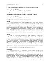
Table 2 summarized the nitriding conditions. Figure 1 shows the illustration of nitriding<br />
apparatus.
Acta Metallurgica Slovaca, 12, 2006, 3 (264 - 274) 267<br />
Table 2 Plasma nitriding conditions<br />
Temperature Time H 2 :N 2 Voltage Current<br />
[K] [ks] ratio [V] [A]<br />
773<br />
36<br />
72<br />
823<br />
36<br />
72<br />
3:1 200 0.1<br />
7<br />
3<br />
2<br />
4<br />
1<br />
5<br />
6<br />
11<br />
12<br />
(1) Specimen<br />
(2) Dummy specimen<br />
(3) Specimen table<br />
(4) Heater in quartz tube<br />
(5) Cathode<br />
(6) Insulator<br />
(7) Thermocouple<br />
(8) Nitrogen gas inlet<br />
(9) Hydrogen gas inlet<br />
(10) To Mechanical booster and rotary pump<br />
(11) Ampere Meter<br />
(12) Voltage meter<br />
(13) DC power supply<br />
8 9<br />
10<br />
13<br />
Fig.1 Scheme of nitriding apparatus<br />
2.4 Characterization<br />
The nitrided samples were analyzed with Glancing Incident angle X-ray<br />
Diffractometer (GIXD) at the incident angle of 1 o and 5 o and X-ray Diffractometer (XRD) in<br />
order to identify phases existing in nitriding layer. Microstructures of nitrided samples were<br />
obtained by optical microscope (OM) and Scanning Electron Microscope (SEM). Qualitative<br />
analysis of each phase in the microstructure was described by using Energy Dispersive<br />
Spectroscopy (EDS) and Electron Probe Microanalysis (EPMA). Micro-Vicker’s hardness<br />
testing was employed to measure the surface hardness and its profiles in the cross-section of<br />
specimens with a load of 50 g.<br />
3. Results and Discussions<br />
3.1 Effect of nitriding temperature and time on depth of nitriding layer<br />
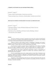
The nitrided layer in <strong>AISI</strong> <strong>H13</strong> tool steel is dark grey layer as shown in Fig. 2. It can<br />
be observed that there are some black color particles precipitate and distribute in the nitriding
Acta Metallurgica Slovaca, 12, 2006, 3 (264 - 274) 268<br />
layer. By higher magnification pictures taken by SEM shown in Fig. 3, the precipitates can be<br />
clearly seen along the nitriding layer which will be discussed later regarding its composition. At<br />
low magnification, 300 times, only large precipitate particles can be seen as shown in Figure 3<br />
(a), however, at 6000 times magnification as shown in Figs. 3 (b) and 3 (c), there exists a large<br />
amount of precipitate particle. Figure 3 (b) is taken at the nitriding front and Fig. 3 (c) is taken<br />
in the middle of the nitriding layer. From these microstructures, it can be concluded that the<br />
precipitated particles are evenly distributed in the nitriding layer. Figure 3 (d), taken by Back<br />
Scattering Electron, shows the microstructure of nitride layer with martensite matrix and needlelike<br />
precipitates.<br />
Fig.2 Cross-sectional microstructure of specimen plasma nitrided at: a) 773 K for 10 ks, b) 823 K for 10 ks, c) 773 K for<br />
20 ks and d) 823 K for 20 ks<br />
The microstructure taken by optical microscopes also display an evolution of the<br />
nitride depth as a function of temperature for 773 and 823 K, respectively. Thickness of<br />
nitriding layer increases with increasing either nitriding time or nitriding temperature as seen in<br />
Fig. 2. After nitriding for 3.6 and 7.2 ks respectively, the thickness of nitriding layer are 96.0<br />
µm and 113.6 µm for the nitriding temperature of 773 K; while, the thickness of nitriding layer<br />
are 129.9 µm to 173.0 µm for the nitriding temperature of 823 K. Each thickness data of<br />
nitrided layers is an average of 30 measurements in optical microscope. Thickness of nitriding<br />
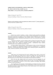
layer as a function of square root of nitriding time for the two temperatures is plotted in Fig. 4.<br />
In Figure 4, growth rate of the nitriding layer, that is the slope of the graph, increases with<br />
increasing nitriding temperature. The thickness of nitriding layer linearly increases with square<br />
root of nitriding time. Consistent with Wagner’s equation [8], meaning that the nitrided layer<br />
growth in plasma nitriding has the parabolic nature which suggests a diffusion controlled<br />
process. The growth rates of nitriding (Kp) are 0.69 µm/s 0.5 and 0.45 µm/s 0.5 when nitriding at<br />
773 K and 823 K respectively. From Fig. 4, some deviation of the square-root time dependence<br />
of thickness of nitriding layer can be seen. At the longer nitriding time, the thickness of
Acta Metallurgica Slovaca, 12, 2006, 3 (264 - 274) 269<br />
nitriding layer tends to decrease. J.D’Haen et al. [9] explained that the deviation of layer<br />
thickness is caused by sputtering or continuous ion bombardment; and hence, this deviation is<br />
expected to occur in plasma nitriding while there is no such effect to caused deviation in gas<br />
nitriding.<br />
Fig.3 Microstructure of <strong>H13</strong> nitrided at 823 K for 72 ks taken by (a) low magnification, (b) high magnification at the<br />
nitriding front, (c) high magnification at the middle of nitriding layer and (d) back scattering electron image at the<br />
middle of nitriding layer<br />
200<br />
Thickness of nitriding layer, E/µm<br />
180<br />
160<br />
140<br />
120<br />
100<br />
80<br />
60<br />
40<br />
20<br />
873 K<br />
773 K<br />
0<br />
0 1 2 3 4 5 6 7 8 9<br />
Nitriding time,t/ ks 0.5<br />
Fig.4 Relations between the thickness of nitriding layers and the square root of nitriding times
Acta Metallurgica Slovaca, 12, 2006, 3 (264 - 274) 270<br />
3.2 Characterization<br />
All specimens are characterized by GIXD at the incident angle of 1˚, 5˚ and XRD.<br />
From calculation by assuming that at the penetration depth X-ray intensity is 0.0001 of the<br />
incident x-ray intensity, X-ray penetration depth are 25.2 µm, 125.6 µm and 1250 µm into iron<br />
matrix for GIXD at the incident angle of 1˚, 5˚ and XRD respectively. Figure 5 shows XRD<br />
profiles of the nitriding samples with different times and temperatures. It can be seen from<br />
Figure 5 that the nitrided layer consist of Fe 3 N (ε), Fe 4 N (γ′), and CrN phases in all samples<br />
which were plasma nitrided at 773 - 823 K for 36 - 72 ks.<br />
Fe 3 N<br />
Fe 4 N<br />
Fe-Cr<br />
CrN<br />
Intensity, I/a.u.<br />
773 K<br />
36 ks<br />
773 K<br />
72 ks<br />
823 K<br />
36 ks<br />
823 K<br />
72 ks<br />
20 40 60 80 100 120<br />
Diffraction angle, θ/2θ<br />
Fig.5 XRD profiles of plasma nitrided samples with different nitriding times and nitriding temperatures<br />
Intensity, I/a.u.<br />
Fe 3 N<br />
Fe 4 N<br />
Fe-Cr<br />
CrN<br />
θ−2θ<br />
5 o<br />
1 o<br />
20 40 60 80 100 120<br />
Diffraction angle, θ/2θ<br />
Fig.6 GIXD at the incident angle of 1 degree and 5 degree and XRD profiles of plasma nitrided sample at 823 K for<br />
72 ks.
Acta Metallurgica Slovaca, 12, 2006, 3 (264 - 274) 271<br />
Considering the phases in the nitriding layer, Fig. 6 shows GIXD profiles at the<br />
incident angle of 1 o and 5 o . The relative intensity of each peak relates to volume fraction of the<br />
corresponding phase. The GIXD profiles in Fig. 6 show that the amount of Fe 3 N phase<br />
increases in the depth direction from the surface. However, at the depth greater than 125 µm,<br />
the volume fraction of Fe 3 N decreases in the same manner as Fe 4 N phase. On the other hand,<br />
the volume fraction of CrN phase continuously increases in the depth direction as can be seen<br />
from the relative intensity of CrN peaks in Fig. 6. It is possible that the CrN is the first phase<br />
that is formed during plasma nitriding of <strong>H13</strong> tool steel. Precipitates of Fe 3 N and Fe 4 N follow<br />
as amount of diffused nitrogen increases. That is because Cr has higher affinity to nitrogen<br />
rather than Fe resulting in easier formation of CrN than Fe 3 N and Fe 4 N [10]. In other words,<br />
sequence of state precipitate is governed by the higher affinity to nitrogen of chromium compare<br />
to that of iron atoms.<br />
Figure 3 shows the precipitated particles inside the nitriding layer. The precipitate<br />
phases can be devided into 2 groups by its morphology. The first groups has a spherical shape<br />
as shown in Figs. 3(a), (b) and (c). The second group has a needle-like shape as shown in Fig.<br />
3(d). The sphere particle was analyzed by EDS as shown in Fig. 7. EDS result of the sample<br />
plasma nitrided at 823 K for 72 ks, analyzed in line scan mode, shows that the iron content line<br />
immediately drop in black particle area compared to the matrix area. carbon and chromium<br />
contents in both areas seem to have same amount by EDS analysis. However, EPMA results are<br />
shown in Fig. 8. The concentration of each element can be known by comparing the color of<br />
each picture. The mapping of iron in Fig. 8 (b) shows that the content of iron in nitrided layer is<br />
less than in the matrix, especially at the black spot in Figure 8 (a). In contrast, the content of<br />
carbon as shown in Fig. 8 (c), nitrogen as shown in Fig. 8 (d), and chromium as shown in Fig. 8<br />
(c)<br />
Fig.7 EDS result of 823 K for 72 ks plasma nitrided specimen: (a) black scattering electron micrographic of black<br />
precipitate, (b) analysis line scan, and (c) Fe, Cr, and C content line<br />
( e) in the nitrided layer are higher than in the matrix. The chromium carbon and nitrogen<br />
concentrations<br />
are the highest at the black spot. EDS and EPMA results that the spherical<br />
shaped precipitated particles contain chromium carbon and nitrogen. With GIXD result, it can<br />
(b)
Acta Metallurgica Slovaca, 12, 2006, 3 (264 - 274) 272<br />
be concluded that these particles are CrN with some amount of carbon. This is consistent of<br />
previous research works [6, 11] which agree that during nitrogen diffusion process in the steel,<br />
nitrogen partly replaces carbon in martensite and form the metal nitride, such as iron nitrides and<br />
chromium nitrides, and the development of fine particles of CrN in nitrided layer is a direct<br />
result of dissolution of prior carbides [7]. For the needle-liked shaped precipitates, it was<br />
reported in literature [11] that it corresponds to iron nitride, which are Fe 3 N and Fe 4 N indicated<br />
by GIXD profiles in Figs. 5 and 6.<br />
Fig.8 EPMA mapping result of specimen plasma nitrided at 823 K for 72 ks; (a) back scattering electron microscopic of<br />
nitrided layer (b) iron (Fe), (c) carbon (C), (d) nitrogen (N), (e) chromium (Cr) mappings<br />
hardness, HV0.50<br />
1400<br />
1200<br />
1000<br />
800<br />
600<br />
400<br />
773K 36ks<br />
773K 72ks<br />
823K 36ks<br />
823K 72ks<br />
H0<br />
200<br />
0<br />
matrix hardness of 823K 72ks<br />
25 125 225 325 425<br />
distance, µm<br />
Fig.9 The hardness profile of plasma nitrided <strong>H13</strong> tool steel
Acta Metallurgica Slovaca, 12, 2006, 3 (264 - 274) 273<br />
3.3 Hardness profiles<br />
Figure 9 shows the evolution of microhardness for all specimens. This shows that<br />
plasma nitriding can improve the surface hardness of <strong>H13</strong> tool steel. The maximum hardness<br />
value locates at the surface with monotonic decreasing of hardness in depth direction. These<br />
hardness profiles show that the case depths of plasma nitriding specimens, about 100 to 200 µm,<br />
correlate well with the microstructures and XRD results. The hardness of nitrided specimens<br />
increases due to precipitation hardening mechanism. Figure 9 also displays the effects of<br />
nitriding time and temperature on hardness profiles. The surface hardness is the highest in the<br />
sample which was plasma nitrided at 773 K for 36 ks and decreases, when either nitriding time<br />
or temperature increases. On the contrary, the hardened depth increases with increasing<br />
nitriding time or temperature.<br />
Conclusions<br />
1. The microstructure of nitrided layer in <strong>H13</strong> tool steel consists of Fe 3 N, Fe 4 N and CrN<br />
phases all over the layer. CrN precipitates prior to Fe4N or Fe3N. CrN coexisted with<br />
chromium carbide in the spherical shaped precipitates.<br />
2. The growth of the nitriding layer is controlled by diffusion process, therefore, the<br />
nitriding depth increases with increasing time and temperature.<br />
3. Plasma nitriding process increase the surface hardness of <strong>H13</strong> tool steel by precipitate<br />
of nitride particle: CrN in spherical shape, Fe 4 N or Fe 3 N in needle-like shape.<br />
Acknowledgement<br />
The authors would like express their gratitude to Ms.Wanaporn Khanitnantharak and<br />
Ms. Thipsukhon Tinsuk of Thai Parkerizing Co., Ltd for performing in EPMA analysis and Mr.<br />
Nattapol Rattanamalee for his assistance with Spark emission spectrometer. This study was<br />
financial supported by Thai Parkerizing Co., Ltd.<br />
Literature<br />
[1] Smith W. F.: Structure and Properties of Engineering Alloys, 2 nd edition, McGraw Hill,<br />
1993, pp. 405 - 409<br />
[2] Miola E.J., de Souza S.D., Olzon-Dionysio M., Spinelli D., dos Santos C.A.: Surface and<br />
Coating Technology, 116 – 119, 1999, pp. 347 - 351<br />
[3] ASM International, ASM Metal Handbook, Vol.1, 1990, pp. 439 - 444<br />
[4] Devi M.U., Mohanty O.N.: Surface and Coating Technology, 107, 1998, pp. 55 - 64<br />
[ 5] Devi M.U., Chakrabory T.K., Mohanty O.N.: Surface and Coating Technology, 116 –119,<br />
1999, pp. 212 - 221<br />
[6] Çapa M., Tamer M., Gülmez T., Bodur C.T.: Turkey Journal Engineering Environment<br />
Science, 24, 2000, pp. 111 - 117<br />
[7] Salas O., Oseguera J., Garei N., Figueroa U.: Journal of Materials Engineering and<br />
Performance, 10, 6, 2001, pp. 649 - 655<br />
[8] Poirier D.R., Geiger G.H.: Transport Phenomena in Materials Processing, USA, 1994, pp.<br />
491 - 493<br />
[9] D’Haen J., Quaeyhaegens C., Knuyt G., D’Olieskaeger M., Stals L.M.: Surface and<br />
Coating Technology, 75-75, 1995, pp. 405 - 411
Acta Metallurgica Slovaca, 12, 2006, 3 (264 - 274) 274<br />
[10] Granito N., Kuwahara H., Aizawa T.: Journal of Materials Science, 37, 2002, pp. 835 -844<br />
[11] Riedel R.: Handbook of Ceramic Hard Materials Vol.1, Wiley-VCH Verlay GmbH,<br />
Germany, 2000, pp. 221 - 222<br />
[12] Brooks Ch. R.: Principles of the Surface Treatment of Steels, Technomic Publishing, USA,<br />
1992, pp. 182 - 190