Types of Acetylene Generators - Communitywebs.org
Types of Acetylene Generators - Communitywebs.org
Types of Acetylene Generators - Communitywebs.org

Create successful ePaper yourself
Turn your PDF publications into a flip-book with our unique Google optimized e-Paper software.
“At the February meeting Jack Muller gave me a<br />
copy <strong>of</strong> a newspaper item from 1906 describing<br />
a fatal episode with an <strong>Acetylene</strong> gas generator<br />
(see Jack’s News paper clipping)<br />
I realised how little I knew about acetylene<br />
generation and so did some research on the<br />
internet. I think the following information gives<br />
a pretty good overview <strong>of</strong> the subject.<br />
I hope you find it interesting.”<br />
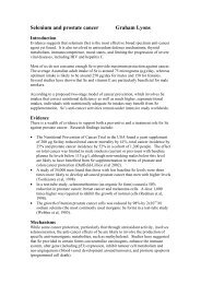
<strong>Types</strong> <strong>of</strong> <strong>Acetylene</strong> <strong>Generators</strong><br />
There are two general methods <strong>of</strong> generating acetylene for domestic<br />
illuminating and heating purposes: that <strong>of</strong> adding carbide to water,<br />
and that in which the water is<br />
mixed with carbide. The two types are illustrated in the<br />
diagrams shown in Figs.1 and 2. The first method, that in<br />
which the carbide is dropped into water, is shown in Fig. 1.<br />
The tank A is the generator and B is the receiver or gas-holder.<br />
The tank A holds a considerable quantity <strong>of</strong> water and is provided<br />
with a container C for holding the supply <strong>of</strong> carbide. The tank A<br />
is connected with the gas-holders by a pipe which extends above<br />
the water line in the tank B, where the gas is allowed to collect in<br />
the gas-holder G. A charge <strong>of</strong> carbide, sufficient to fill the holder with gas,<br />
is pushed into the tank A by raising the lever H. Immediately the water begins to combine<br />
with the carbide and the bubbles <strong>of</strong> gas pass up through the water and are conducted into the tank B.<br />
The holder G is lifted by the gas and its weight furnishes the pressure necessary to force the gas into the<br />
pipes, which conduct it to the burners. If this machine were provided with the proper mechanism to feed into<br />
the generator a supply <strong>of</strong> carbide whenever the gas in the holder is exhausted, the machine would<br />
represent the modern "carbide to water" generator.<br />
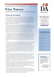
The "water to carbide" generator is shown diagrammatically in Fig.<br />
2. As in the other figure, A is the generator and B is the gas-holder.<br />
A supply <strong>of</strong> carbide S is placed in the generator and water from a<br />
tank C is allowed to drip or spray onto the carbide.<br />
The gas collects in the gas-holder as before. This apparatus<br />
represents in principle the parts <strong>of</strong> a machine for generating<br />
acetylene by this process. The actual machines are arranged to<br />
perform the functions necessary to make the machines automatic<br />
in their action.<br />
Whatever the type <strong>of</strong> the machine, the object is to keep in the<br />
holders a sufficient amount <strong>of</strong> gas with which to supply the<br />
demand made on the plant. Machines representing each <strong>of</strong> the Diagram <strong>of</strong> a carbide-to-water acetylene-gas generator.<br />
types described are to be obtained, but the greater number <strong>of</strong><br />
those manufactured are <strong>of</strong> the "carbide to water" form.<br />
In the formative period <strong>of</strong> acetylene generators many accidents <strong>of</strong><br />
serious consequence resulted from imperfect mechanism.<br />
Imperfections have been gradually eliminated until the machines<br />
which have survived are efficient in action and mechanically free<br />
from dangerous eccentricities. The qualities demanded <strong>of</strong> a good<br />
generator are: There must be no possibility <strong>of</strong> an explosive<br />
mixture in any <strong>of</strong> the parts; it must insure a cool generation <strong>of</strong> gas;<br />
it must be well-constructed and simple to operate; it should create<br />
no pressure above a few ounces; it should be provided with an<br />
indicator to show how low the charge <strong>of</strong> carbide has become in<br />
order that it may be recharged in due season, and it must use up<br />
Diagram <strong>of</strong> a water-to-carbide acetylene-gas machine.<br />
the carbide completely.
Because <strong>of</strong> the fact that the greater number <strong>of</strong> acetylene-gas machines <strong>of</strong> today are <strong>of</strong> the "carbide to<br />
water" type, in the description to follow that type <strong>of</strong> machine is used. They are generally made in two parts,<br />
one part containing the generating apparatus and the other acting as gasometer (gas-holder), but some<br />
machines made in which one cell contains both the generator and gasometer.<br />
In Fig. 211 is shown a two-part, gravity-fed machine, in which all <strong>of</strong> the internal working parts are exposed<br />
to view. The tank (a), as in the diagram, is the generator and the tank (6) contains the gasometer marked<br />
G. Each tank possesses a number <strong>of</strong> appliances which are necessary to make the machine automatic in its<br />
action. The part C <strong>of</strong> the generator contains the supply <strong>of</strong> carbide, broken into small pieces, a portion <strong>of</strong><br />
which is dropped into the water whenever additional gas is required.<br />
The feed mechanism F is controlled by the gasometer bell G, which is<br />
buoyed up by the gas it contains. When the supply <strong>of</strong> gas becomes<br />
low, the descending bell carries with it the end <strong>of</strong> the lever F, which<br />
is attached to the feed valve; this motion raises the feed valve and<br />
allows some <strong>of</strong> the carbide to fall into the water. The gas that is<br />
immediately generated passes into the gasometer through the<br />
pipe P, and as the bell is raised by the accumulating gas the<br />
valve V is closed. The gas as it enters the gasometer passes<br />
through a hollow device W, that looks like an inverted T, the<br />
lower edge <strong>of</strong> which is tooth-shaped and extends below the<br />
surface <strong>of</strong> the water. The gas, in passing this irregular surface,<br />
is broken up and comes through the water in little bubbles, in<br />
order that it may be washed clean <strong>of</strong> dust. This device also<br />
prevents the return <strong>of</strong> the gas to the generator tank during the<br />
process <strong>of</strong> charging. The gas escapes from the bell through<br />
the pipe S to the filter D, where any dust that may have<br />
escaped the washing process is removed by a felt filter. It<br />
finally leaves the machine by the pipe L, at which point it enters<br />
the system through which it is conveyed to the different lighting fixtures.<br />
Sectional view <strong>of</strong> the Colt acetylene-gas machine.<br />
It will be noticed that the tank (b) is divided into two compartments, the upper portion containing the water<br />
in which the gasometer floats. The lower compartment is also partly filled with water which acts as a safety<br />
valve to prevent any escape <strong>of</strong> gas into the room in which the generator is located. The lower end <strong>of</strong> the<br />
pipes P and S are immersed in the water at the bottom chamber <strong>of</strong> the tank, from which the gas could<br />
escape in case too much is generated and finally exit through the vent pipe U to the outside air.<br />
The float A in the tank (a) is a safety device that prevents the introduction <strong>of</strong> carbide unless the tank<br />
contains a full supply <strong>of</strong> water. The float is a hollow metal cylinder connected by a rod to a hinged cup<br />
under the bottom opening <strong>of</strong> the carbide holder. When the water is withdrawn from the generator, the float<br />
falls and the cup shuts <strong>of</strong>f the carbide outlet.<br />
The accumulation <strong>of</strong> lime, from the disintegrated carbide, requires occasional removal from the tank (a);<br />
the valve K is provided for this<br />
purpose. The lever S is used to<br />
stir up the lime which is deposited<br />
on the bottom <strong>of</strong> the tank, that it<br />
may be carried out with the discharged<br />
water. Machines <strong>of</strong> this<br />
kind that are safeguarded against<br />
leakage <strong>of</strong> gas or the possibility <strong>of</strong><br />
accumulated pressure are<br />
practically free from danger in the<br />
use <strong>of</strong> acetylene.<br />
The accidental leakage <strong>of</strong> gas<br />
from defective pipes and fixtures<br />
produce only the element <strong>of</strong> risk<br />
that is assumed with the use <strong>of</strong><br />
any other form <strong>of</strong> gas for<br />
illuminating purposes.<br />
<strong>Acetylene</strong> is distributed through<br />
the house in pipes in the same<br />
manner as for ordinary illuminating<br />
gas.<br />
Sectional view <strong>of</strong> a house equipped with acetylene lights and domestic heating apparatus.
<strong>Acetylene</strong> gas burner.<br />
The sizes <strong>of</strong> the pipes to suit the varying conditions <strong>of</strong> use are regulated by rules<br />
provided by the National Board <strong>of</strong> Fire Underwriters.<br />
These rules state definitely the sizes <strong>of</strong> pipes required<br />
for machines <strong>of</strong> different capacities. Rules <strong>of</strong> this kind<br />
and others that specify all matters relating to the use <strong>of</strong><br />
acetylene may be obtained from any fire insurance<br />
agent.<br />
The general plan <strong>of</strong> piping is shown in Fig. 4.<br />
The generator G is in this case a "water to carbide"<br />
machine and is shown connected to the kitchen range,<br />
as well as the pipe system which may be traced to the<br />
lamps in the different rooms, to the porch lights and to<br />
the boulevard lamp in front <strong>of</strong> the building.<br />
Fig. 7. - Electric igniter for acetylene gas burners.<br />
The type <strong>of</strong> burner used in acetylene lamps is shown .<br />
The gas issues from two openings to form the jet as it<br />
appears in the engraving. These burners are made in<br />
sizes to consume 1/4, 1/2, 3/4,and 1 foot per hour<br />
depending on the amount <strong>of</strong> light demanded.<br />
Carbide is CaC2. It is produced by treating lime and<br />
Coke in an electric arc furnace. An energy demanding<br />
process which was apparently only possible commercially<br />
in the US with the advent <strong>of</strong> the Niagara falls<br />
hydro electric scheme.<br />
The reaction formula for the production <strong>of</strong> acetylene is:<br />
CaC2 + 2H2O = C2H2 + CaOH2 that is Calcium Carbide +<br />
Water = <strong>Acetylene</strong> gas + Calcium hydroxide<br />
Dick Turpin<br />
Electric igniter for acetylene gas<br />
burners.<br />
Electric igniter for acetylene gas<br />
burners.