Title: Installation & Maintenance â AP Pneumatic Positioner - Kinetrol
Title: Installation & Maintenance â AP Pneumatic Positioner - Kinetrol
Title: Installation & Maintenance â AP Pneumatic Positioner - Kinetrol

You also want an ePaper? Increase the reach of your titles
YUMPU automatically turns print PDFs into web optimized ePapers that Google loves.
<strong>Title</strong>: <strong>Installation</strong> & <strong>Maintenance</strong> – <strong>AP</strong> <strong>Pneumatic</strong> <strong>Positioner</strong><br />
1. CONTENTS.<br />
Page<br />
Section<br />
1 1. Contents<br />
2 2. <strong>Installation</strong> -<br />
3<br />
2.1 Direct Mounting Units onto <strong>Kinetrol</strong> <strong>Positioner</strong><br />
Actuators<br />
2.2 Mounting of Discrete <strong>Positioner</strong>s.<br />
2.3 Air and Electrical Connections.<br />
4 3. Description of Operation<br />
5 4. Settings and Adjustments –<br />
6<br />
4.1 Change of Direction for rising signal (direct mounted)<br />
4.2 Zero and Range Adjustment<br />
4.3 Speed Control<br />
4.4 Change of Direction for rising signal (Discrete)<br />
7 5. <strong>Maintenance</strong> and Troubleshooting<br />
8-10 6. Angle Retransmit Option –<br />
6.1 <strong>Installation</strong><br />
6.2 Change of Direction for rising signal<br />
6.3 Zero and Range Adjustment<br />
6.4 Change of Direction for rising signal (Discrete)<br />
6.5 Change of Angle Retransmit direction without<br />
changing positioner direction.<br />
11-13 7. Spare Parts -<br />
7.1 Exploded View<br />
7.2 Spare Part Numbers<br />
Issue<br />
E<br />
R.C.C.<br />
17/11/08<br />
Trading Estate Farnham Surrey England<br />
Doc. No.TD 106<br />
Page 1 of 13<br />
TD106 – 11/08:INDEX H\Drawing office docs. Master KF WI TD etc.\current TD sheet masters
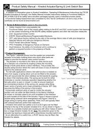
2. INSTALLATION.<br />
<strong>Title</strong>: <strong>Installation</strong> & <strong>Maintenance</strong> – <strong>AP</strong> <strong>Pneumatic</strong> <strong>Positioner</strong><br />
<strong>Positioner</strong>s can be supplied direct-mounted, or ready to be direct-mounted, onto <strong>Kinetrol</strong> rotary actuators, or in standalone<br />
(discrete) form for fitting via a mount kit to any 90 degree rotary or linear actuator. If the positioner is supplied<br />
ready mounted on an actuator, sections 2.1 & 2.2 can be bypassed. <strong>Positioner</strong>-type <strong>Kinetrol</strong> actuators (ready for direct<br />
mount of positioners) are available in models 050 to 140 inclusive.<br />
2.1 Mounting of Direct Mounting Units onto <strong>Kinetrol</strong> <strong>Positioner</strong>-Type Actuators (without angle<br />
retransmit)<br />
Note: For angle retransmit versions, refer to section 6.1<br />
2.1.1 Move actuator vane to mid travel position, with its output square as shown in Figure 1. This is advisable to prevent<br />
subsequent error in orientating positioner coupling. (This is not necessary with spring return actuators as there can be no<br />
confusion with square orientation).<br />
2.1.2 Remove positioner cover and undo the two M4 screws retaining the red angle scale plate and remove coupling as<br />
shown in Figure 2.<br />
2.1.3 Bolt the positioner body to the actuator in the orientation shown in Figure 1 taking care that the two O'rings are in<br />
place to seal the ports to the actuator (place a small amount of grease onto the O'rings to keep them in place) and that the<br />
actuator shaft is centred in the body.<br />
2.1.4 Observe the direction that the cam moves with a rising signal and, if correct, place the coupling on the actuator<br />
square with one hand whilst pulling back the mechanism with the other (refer to Figure 2). If the direction is not as required<br />
then refer to section 4.1. If the actuator has been correctly positioned near mid-stroke, the cam follower will contact the<br />
cam at approximately half way. Ensure that the coupling is pushed fully onto the actuator square and tighten the central<br />
fixing screw which will have the effect of centralising the cam follower on cam. Refit the angle scale plate.<br />
2.2 Mounting of Discrete <strong>Positioner</strong>.<br />
The design and manufacture of the mount kit between the positoner and actuator is outside the scope of this document. It<br />
is essential that the shaft of the actuator is well aligned with the positioner shaft and that the two are coupled together with<br />
a minimum of backlash as this will reduce the performance of the positioner/actuator combination.<br />
It is essential that the 90 degree travel of the actuator moves the positioner coupling through the correct 90 degrees of<br />
travel. This can be achieved by either observing the position of the indicator on the lid or the position of the cam or internal<br />
indicator with the lid removed.<br />
Issue<br />
E<br />
R.C.C.<br />
17/11/08<br />
Trading Estate Farnham Surrey England<br />
Doc. No.TD 106<br />
Page 2 of 13
<strong>Title</strong>: <strong>Installation</strong> & <strong>Maintenance</strong> – <strong>AP</strong> <strong>Pneumatic</strong> <strong>Positioner</strong><br />
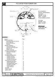
2.3 <strong>Pneumatic</strong> and Electrical Connections.<br />
2.3.1 Air Supply<br />
Connect main air supply (pressure between 3.5 and 7 bar or 50 and 100psi) to the supply port indicated in figure 3. Also<br />
connect signal air supply (pressure between 0.2 bar and 1 bar or 3 psi and 15 psi) to the inlet of the diaphragm housing.<br />
It is important that the air is clean, dry and oil free. Quality class 6.4.4 (taken from ISO standard 8573.2001) is adequate.<br />
This implies 5 micron max. Particle size, 3 deg. C dew point max. and 5mg per cubic metre max. oil content.<br />
2.3.2 Angle Retransmit Option Supply.<br />
The optional angle retransmit circuit is loop powered, requiring 8 to 30 volts to drive the 4-20mA current through it. The<br />
current which passes is linearly in proportion to the shaft angle.<br />
The cable entry has the option of a cable gland fitting or 4-way DIN plug. With the cable gland entry the wires are directly<br />
connected to the internal Connector Block. An internal earth connection is provided if required. If the DIN plug option is<br />
fitted then the internal connections have already been made as shown in Figure 3. An external earth connection is also<br />
provided if this is required.<br />
2.3.3 External Actuator Ports.<br />
For positioners not fitted directly onto <strong>Kinetrol</strong> <strong>Positioner</strong> type Actuators, two external ports are provided for connecting<br />
the positioner outlets to the actuator. The size of the ports is dependant on the positioner ordering code. These ports can<br />
also be used for fitting pressure gauges if desired.<br />
Issue<br />
E<br />
R.C.C.<br />
17/11/08<br />
Trading Estate Farnham Surrey England<br />
Doc. No.TD 106<br />
Page 3 of 13
<strong>Title</strong>: <strong>Installation</strong> & <strong>Maintenance</strong> – <strong>AP</strong> <strong>Pneumatic</strong> <strong>Positioner</strong><br />
3. DESCRIPTION OF OPERATION.<br />
The <strong>AP</strong> <strong>Positioner</strong> works using the principal of a 'force balance' spool system with mechanical cam feedback. The air<br />
input signal (normally 3-15psi) is applied to a diaphragm which produces a force on the force balance lever which is<br />
proportional to the signal pressure. The resulting torque on the lever is balanced by the force produced from the<br />
feedback spring which is also joined to the lever.<br />
A proportional flow spool valve is the third element attached to the lever. This is positioned at its central closed position<br />
when the lever is at the mid-stroke position which occurs when the actuator is at the desired angle. Several different<br />
versions of this valve are available with different flow capacities designed to give optimum performance when fitted to<br />
the range of <strong>Kinetrol</strong> actuators.<br />
The feedback cam is retained by a coupling which, in the case of a <strong>Kinetrol</strong> direct mounted positioner, is held onto the<br />
vane square by a collet. For discrete versions, the coupling is retained in bearings and connected by either a male<br />
square or 'Namur' style connector.<br />
The cam provides positional feedback via a unique four bar linkage which ensures a linear movement of the cam<br />
follower whether the cam is set for clockwise or anticlockwise movement for a rising signal. The lower part of the<br />
linkage is attached to the other end of the feedback spring which stretches the spring as the cam is rotated to produce<br />
the feedback force mentioned earlier. The standard cam produces a linear characteristic, but alternative profiles are<br />
available.<br />
The common adjustments are split into zero and range. Both are achieved without the need for special tools and the<br />
actual adjustments are made using finger pressure only.<br />
Air passages in the main body are provided with the capability of many options with a minimum of changes. External<br />
ports are provided on all models to allow for external connection to the actuator or for the fitting of pressure gauges if<br />
desired. Three main air flow options are available (as detailed in the <strong>AP</strong> literature). The two lower flow rate options (<strong>AP</strong><br />
& MP) are affected by change of valve size and tapping size in the body. The largest flow rate option (HP) not only has<br />
a larger valve but also a different port plate with 3/8 tapping and external combination silencer/snubbers.<br />
The mounting options are accommodated by three different channel plate designs. The channel plate is the plate fitted<br />
to the base of the unit. The smallest is dedicated to direct mounting on an 050 Actuator. The second is used for direct<br />
mounting on Actuators 070 to 140. The third is used for discrete models having a Namur mounting hole pattern.<br />
An optional angle retransmit can be fitted within the positioner body and additional options of I/P controller and limit<br />
switch box can also be fitted allowing a wide range of switch options to be specified.<br />
Issue<br />
E<br />
R.C.C.<br />
17/11/08<br />
Trading Estate Farnham Surrey England<br />
Doc. No. TD 106<br />
Page 4 of 13
<strong>Title</strong>: <strong>Installation</strong> & <strong>Maintenance</strong> – <strong>AP</strong> <strong>Pneumatic</strong> <strong>Positioner</strong><br />
4. SETTINGS AND ADJUSTMENTS.<br />
The positioner will have been factory set to the requirements given in the ordering code ( i.e. the direction of rotation for<br />
a rising pressure signal and the range and zero settings). However, if these settings need to be changed, the following<br />
section describes the procedure for achieving this.<br />
4.1 Change of Direction for Rising Signal (direct mounting units only).<br />
4.1.1 Move the actuator to approximately mid-position to avoid problems in correct orientation later. This is obviously not<br />
possible or necessary with spring return models because the position of the vane will be known. Reduce both main supply<br />
and signal pressures to zero.<br />
4.1.2 Remove positioner cover and undo the two M4 screws retaining the red angle scale plate and remove, as shown in<br />
Figure 5. Loosen the central coupling screw sufficiently to draw the coupling off the actuator square.<br />
4.1.3 Pull the two halves of the coupling apart sufficiently to allow the cam to be withdrawn from its location peg as shown<br />
in Figure 6. Flip the cam over and push it back into the slot between the two coupling halves and locate it back on the peg.<br />
4.1.4 If when the coupling was removed, the collet was left behind on the actuator square, remove the collet from the<br />
square and push it into the lower half of the coupling ensuring that it locates in the semicircular 'pip'. Tighten the clamping<br />
screw by two turns before placing it back on the actuator square such that the cam follower is approximately half way up<br />
the rise of the cam and tighten the clamping screw. Replace the angle scale plate.<br />
4.1.5 Undo the changeover block central screw and rotate it by a quarter turn and replace and tighten screw. For your<br />
convenience, the changeover block is marked 'A' and 'C' which refers to 'anticlockwise' and 'clockwise' respectively.<br />
Ensure the required letter is placed opposite the arrow marked on the top of the valve block.<br />
Issue<br />
E<br />
R.C.C.<br />
17/11/08<br />
Trading Estate Farnham Surrey England<br />
Doc. No. TD 106<br />
Page 5 of 13
<strong>Title</strong>: <strong>Installation</strong> & <strong>Maintenance</strong> – <strong>AP</strong> <strong>Pneumatic</strong> <strong>Positioner</strong><br />
4.2 Zero and Range Adjustment (refer to Figure 4).<br />
4.2.1 Move the actuator/positioner to the zero end of the stroke (i.e. when the cam follower is at the beginning of its rise).<br />
This can be most easily achieved by pressurising the main air supply without any signal air pressure (spring return models<br />
will already be at this position. Exhaust the supply air and move the internal indicator to indicate just below zero on the<br />
angle scale.<br />
4.2.2 Set the coarse zero by slackening the coupling screw by approximately half of a turn until the top part of the coupling<br />
can be rotated by hand and rotate until the cam follower just starts to rise up the cam profile. Retighten the screw.<br />
4.2.3 Turn on the main air supply and carefully increase the signal supply pressure to 3psi (0.2Bar). Slacken the fine zero<br />
adjustment clamp screw and rotate zero adjuster using thumb pressure so that the actuator moves to indicate zero on the<br />
internal indicator. Tighten clamp screw.<br />
4.2.4 Increase the signal pressure to 15psi (1 Bar). Slacken the range adjuster clamp screw and rotate the adjuster knob<br />
between thumb and forefinger until the actuator moves to the desired end stroke position (normally 90 degrees) as<br />
indicated on the internal indicator. Re-tighten the clamp screw.<br />
4.2.5 Reduce the signal air pressure again to 3 psi and check that the zero position has not changed.<br />
4.3 Speed Control.<br />
Maximum actuator speed can be regulated by the two following methods:<br />
a.) Changing the valve spool/liner size. The valve size is normally specified at the point of ordering by the letters '<strong>AP</strong>', 'MP'<br />
or 'HP'. This method, however, not only effects the actuator speed but also effects the 'gain' and therefore control stability<br />
of the unit and care must be taken not to specify a too high flow valve for a given size of actuator. <strong>Kinetrol</strong> Ltd has<br />
recommendations (shown in the <strong>AP</strong> literature) for each size of the actuator<br />
or<br />
b.) adjustment of the built in flow restrictors (shown in Figure 4) is achieved using a screwdriver. There are two restrictors,<br />
one for each direction of travel. Clockwise rotation, this will reduce the actuator speed. '<strong>AP</strong>' and 'MP' size units with 1/8 or<br />
1/4 ports are controlled in this way but 'HP' size units having 3/8 ports are fitted with external silencer/restrictors which are<br />
adjusted using an allen key fitted down the centre of the adjuster.<br />
4.4 Change of Direction for Rising Signal (discrete units).<br />
4.4.1 Move actuator as in Section 4.1.1.<br />
4.4.2 Remove positioner cover and undo the three M4 screws retaining the red retransmit plate, as shown in Figure 7.<br />
Loosen the central coupling screw sufficiently to pull the coupling complete with the retransmit assembly off the actuator<br />
connection.<br />
4.4.3 Remove the internal indicator from the coupling and withdraw the coupling from the retransmit plate.<br />
4.4.4 Pull the two halves of the coupling apart sufficiently to allow the cam to be withdrawn from its location peg. Flip the<br />
cam over and push it back into the slot between the two coupling halves and locate it back on the peg.<br />
4.4.5 Refit the coupling to the retransmit plate and slide the internal indicator over the top of the coupling.<br />
4.4.6 If when the coupling was removed, the collet was left behind on the actuator connection, remove the collet from the<br />
connection and push it into the lower half of the coupling ensuring that it locates in the semicircular 'pip' and tighten the<br />
clamping screw by two turns. Place the coupling and retransmit plate back on the actuator connection such that the cam<br />
follower is approximately half way up the rise of the cam and pull back the spring lever with the other hand and tighten the<br />
coupling clamping screw. Re-tighten the retransmit plate retaining screws.<br />
4.4.7 The internal changeover block is not effective with a discrete positioner. The changeover of the airflow path is<br />
achieved by swapping over the external connections. It may also be preferred to turn the positioner through 180 degrees<br />
to simplify the external pipe runs.<br />
4.4.8 The adjustment of zero and range is completed as in section 4.2.<br />
Issue<br />
E<br />
R.C.C.<br />
17/11/08<br />
Trading Estate Farnham Surrey England<br />
Doc. No. TD 106<br />
Page 6 of 13
<strong>Title</strong>: <strong>Installation</strong> & <strong>Maintenance</strong> – <strong>AP</strong> <strong>Pneumatic</strong> <strong>Positioner</strong><br />
5. MAINTENANCE AND TROUBLESHOOTING.<br />
The <strong>AP</strong> positioner is designed for a long life with very little maintenance required if it is supplied with clean, dry oil free air,<br />
as recommended in section 2.3.<br />
When the positioner lid is removed, take care not to remove all grease from the lid/coupling seal. If it does need<br />
replenishing then ensure that a synthetic grease is used as a mineral oil grease will adversely affect this seal.<br />
If, however, any of the parts do need replacement because of adverse conditions, then refer to <strong>Kinetrol</strong> Ltd for spare parts<br />
together with any instructions for replacing and resetting.<br />
The following trouble shooting guide should help in the unlikely event of a problem with the performance of the unit. If<br />
problems persist, contact your local <strong>Kinetrol</strong> distributor or <strong>Kinetrol</strong> Ltd for further advice.<br />
TABLE 1. Troubleshooting Guide<br />
Failure to move when signal air and mains air is applied<br />
- Check mains air pressure is sufficient to produce enough torque from actuator<br />
- Check signal pressure using pressure gauge in gauge port or check that the force balance lever is being pushed by<br />
the input diaphragm with the lid removed<br />
- Has the coupling been positioned at the correct angular position on the actuator?<br />
- Has the changeover block been set correctly for the direction of rotation (direct mounted units) or the external port<br />
connections been fitted the correct way around (discrete units)?<br />
- Is the air quality poor, causing the spool to jam? This can be checked by manually moving the spool carefully by<br />
hand with the lid removed.<br />
- Is the actuator or whatever it is connected to jammed? This can be checked by again moving the force balance lever<br />
manually to check if the actuator responds (air will normally be heard hissing into the actuator when this is done).<br />
Actuator moves too slowly upscale or down scale:<br />
- Is the mains air pressure too low for the load being moved or the actuator too small?<br />
- Have one or both flow adjuster screws been screwed in too far?<br />
- Is the air contaminated causing the spool movement to become sluggish?<br />
- Is the actuator volume too large for the spool flow rate chosen?<br />
Lack of sensitivity:<br />
- Is the spool sticky, caused by a contaminated air supply?<br />
- Does the actuator exhibit poor stick slip qualities? This may be especially true if it is not <strong>Kinetrol</strong> and will normally be<br />
seen also as a jerky movement.<br />
Excessive Hysteresis:<br />
- Has the inside of the positioner box become contaminated causing the force balance mechanism bearings to<br />
become sticky?<br />
- Is the actuator load excessive causing it to struggle to achieve position?<br />
Overshoot/Instability:<br />
- Is the spool valve chosen too large for the size of the actuator?<br />
- Is the inertia loading too great for the size of actuator chosen? Refer to <strong>Kinetrol</strong> for allowable limits.<br />
- Have the snubbers been used to slow the load down?<br />
Issue<br />
E<br />
R.C.C.<br />
17/11/08<br />
Trading Estate Farnham Surrey England<br />
Doc. No. TD 106<br />
Page 7 of 13
6. ANGLE RETRANSMIT OPTION.<br />
<strong>Title</strong>: <strong>Installation</strong> & <strong>Maintenance</strong> – <strong>AP</strong> <strong>Pneumatic</strong> <strong>Positioner</strong><br />
6.1.1 Move actuator vane to mid travel position, with its output square as shown in Figure 1. This is advisable to prevent<br />
subsequent error in orientating positioner coupling. (This is not necessary with spring return actuators as there can be no<br />
confusion with square orientation).<br />
6.1.2 Remove positioner cover and unscrew the three M4 screws retaining the red retransmit plate, release the two wires<br />
on the terminal block connected to the DIN plug (if fitted), as shown in Figure 7, and carefully remove coupling and<br />
retransmit assembly as one unit.<br />
6.1.3 Bolt the positioner body to the actuator in the orientation shown in Figure 1 taking care that the two O'rings are in<br />
place to seal the ports to the actuator (place a small amount of grease on to the O'rings to keep them in place) and that<br />
the actuator shaft is centred in the hole in the body.<br />
6.1.4 Observe the direction that the cam moves with a rising signal and that the retransmit strap is fitted to the correct slot<br />
in the lower coupling as marked (C & A for clockwise and anticlockwise respectively). If the direction is not as required<br />
then refer to section 6.2. If correct, place the coupling and retransmit assembly on the actuator square with one hand<br />
whilst pulling back the mechanism and two DIN plug wires with the other (refer to Figure 6). If the actuator has been<br />
correctly positioned near mid-stroke, the cam follower will contact the cam as approximately half way.<br />
6.1.5 Ensure that the coupling is pushed fully on to the actuator square and tighten the central fixing screw which will<br />
have the effect of centralising the cam follower on the cam track. Retighten the three angle retransmit retaining screws<br />
and refit the two DIN plug wires (if fitted).<br />
6.2 Change of Direction for Rising Signal (direct mounting units only).<br />
6.2.1 Move the actuator to approximately mid-position to avoid problems in correct orientation later. This is obviously not<br />
possible or necessary with spring return models because the position of the vane will be known. Reduce both main<br />
supply and signal pressures to zero.<br />
6.2.2 Remove positioner cover and undo the three M4 screws retaining the red retransmit plate, release the two wires on<br />
the terminal block connected to the DIN plug (if fitted), as shown in figure 7. Loosen the central coupling screw sufficiently<br />
to carefully pull the coupling complete with the retransmit assembly off the actuator square.<br />
6.2.3 Release the potentiometer strap from the slot in the lower coupling, as shown in figure 8, remove the internal<br />
indicator from the coupling and withdraw the coupling from the retransmit plate.<br />
Issue<br />
E<br />
R.C.C.<br />
17/11/08<br />
Trading Estate Farnham Surrey England<br />
Doc. No. TD 106<br />
Page 8 of 13
<strong>Title</strong>: <strong>Installation</strong> & <strong>Maintenance</strong> – <strong>AP</strong> <strong>Pneumatic</strong> <strong>Positioner</strong><br />
6.2.4 Pull the two halves of the coupling apart sufficiently to allow the cam to be withdrawn from its location peg. Flip the<br />
cam over and push it back into the slot between the two coupling halves and locate it back on the peg.<br />
6.2.5 Refit the coupling to the retransmit plate, slide the internal indicator over the top of the coupling and refit the<br />
potentiometer strap into one of the two marked slots of the lower coupling (marked 'A' and 'C' for anticlockwise and<br />
clockwise movement respectively).<br />
6.2.6 If when the coupling was removed, the collet was left behind on the actuator square, remove the collet from the<br />
square and push it into the lower half of the coupling ensuring that it locates in the semicircular 'pip' and tighten the<br />
clamping screw by two turns. Place the coupling and retransmit assembly back on the actuator square so that the cam<br />
follower is approximately half way up the rise of the cam whilst holding back the two retransmit wires and pull back the<br />
spring lever with the other hand and tighten the coupling clamping screw. Re-tighten the retransmit plate retaining screws<br />
and refit the retransmit wires to the terminal block.<br />
6.2.7 To ensure a rise in retransmit signal with rising input pressure signal, the top and bottom wires on the feedback<br />
potentiometer must be reversed in the connector located on the circuit. The central wire does not change.<br />
6.2.8 Undo the changeover block central screw and rotate it by a quarter turn and replace and tighten screw. The<br />
changeover block is marked 'A' and 'C' which refers to 'anti-clockwise' and 'clockwise' respectively. Ensure the required<br />
letter is placed opposite the arrow marked on the top of the valve block.<br />
6.3 Zero and Range Adjustment (refer to Figure 7).<br />
Setting of the mechanical zero and range for the positioner with an angle retransmit is the same as described in section<br />
4.2. The retransmit circuit must also be set for zero and range which is described below.<br />
6.3.1 Set the circuit zero adjustment to the central position and connect a 4-20ma electrical source via the DIN plug or<br />
terminal block.<br />
6.3.2 Set the positioner to zero degrees or the input pressure to 3 psi (0.2 Bar)<br />
6.3.3 Slacken the two screws which clamp the potentiometer to the retransmit plate but do not remove. Rotate the<br />
potentiometer slowly using finger pressure until the electrical display shows 4ma.<br />
6.3.4 Increase the air signal pressure to 15 psi (1 Bar) to set the positioner at 90 degrees. Adjust the Span potentiometer<br />
to read 20ma.<br />
6.3.5 Repeat steps 6.3.2 to 6.3.4 until the desired readings are obtained at both ends of the stroke. The fine zero<br />
potentiometer can be used to obtain a more precise reading at the zero position.<br />
6.3.6 Tighten the two potentiometer clamp screws.<br />
6.4 Change of Direction for Rising Signal (discrete units).<br />
6.4.1 Move actuator as in Section 6.2.1.<br />
6.4.2 Remove positioner cover and undo the three M4 screws retaining the red retransmit plate, release the two wires on<br />
the terminal block connected to the DIN plug (if fitted), as shown in figure 7. Loosen the central coupling screw sufficiently<br />
to pull the coupling complete with the retransmit assembly off the actuator connection.<br />
6.4.3 Release the potentiometer strap from the slot in the lower coupling, as shown in Figure 8, remove the internal<br />
indicator from the coupling and withdraw the coupling from the retransmit plate.<br />
6.4.4 Pull the two halves of the coupling apart sufficiently to allow the cam to be withdrawn from its location peg. Flip the<br />
cam over and push it back into the slot between the two coupling halves and locate it back on the peg.<br />
6.4.5 Refit the coupling to the retransmit plate and slide the internal indicator over the top of the coupling and refit the<br />
potentiometer strap into one of the two marked slots of the lower coupling (marked 'A' and 'C' for anticlockwise and<br />
clockwise movement respectively).<br />
Issue<br />
E<br />
R.C.C.<br />
17/11/08<br />
Trading Estate Farnham Surrey England<br />
Doc. No. TD 106<br />
Page 9 of 13
<strong>Title</strong>: <strong>Installation</strong> & <strong>Maintenance</strong> – <strong>AP</strong> <strong>Pneumatic</strong> <strong>Positioner</strong><br />
6.4.6 If when the coupling was removed, the collet was left behind on the actuator connection, remove the collet from<br />
the connection and push it into the lower half of the coupling ensuring that it locates in the semicircular 'pip' and<br />
tighten the clamping screw by two turns. Place the coupling and retransmit plate back on the actuator connection so<br />
that the cam follower is approximately half way up the rise of the cam whilst holding back the two retransmit wires<br />
and pull back the spring lever with the other hand and tighten the coupling clamping screw. Re-tighten the retransmit<br />
plate retaining screws and refit the retransmit wires to the terminal block.<br />
6.4.7 The internal changeover block is not effective with a discrete positioner. The changeover of the air flow path is<br />
achieved by swapping over the external connections. It may also be preferred to turn the positioner through 180<br />
degrees to simplify the external pipe runs.<br />
6.4.8 The adjustment of zero and range is completed as in section 6.3.<br />
6.5 Change of Angle Retransmit Direction Without Changing <strong>Positioner</strong> Direction<br />
If a non-standard rise in retransmit signal is required without a change in positioner direction, then this can be<br />
achieved by the following procedure.<br />
6.5.1 Swap the top and bottom wires on the angle retransmit circuit which connect to the potentiometer.<br />
6.5.2 Repeat the zero and range set-up procedure described in section 6.3.<br />
Issue<br />
E<br />
R.C.C.<br />
17/11/08<br />
Trading Estate Farnham Surrey England<br />
Doc. No. TD106<br />
Page 10 of 13
<strong>Title</strong>: <strong>Installation</strong> & <strong>Maintenance</strong> – <strong>AP</strong> <strong>Pneumatic</strong> <strong>Positioner</strong><br />
Issue<br />
E<br />
R.C.C.<br />
17/11/08<br />
Trading Estate Farnham Surrey England<br />
Doc. No. TD 106<br />
Page 11 of 13
<strong>Title</strong>: <strong>Installation</strong> & <strong>Maintenance</strong> – <strong>AP</strong> <strong>Pneumatic</strong> <strong>Positioner</strong><br />
ITEM<br />
NO.<br />
1<br />
2<br />
DESCRIPTION<br />
SPARES PART NUMBER<br />
<strong>AP</strong> MP HP<br />
050 070 090 10 / 12 / 14 16/18/20/30<br />
Cover Assembly - standard* SP1200 SP1200 SP1200 SP1200 SP1200<br />
Cover Assembly – for switch box* SP1201 SP1201 SP1201 SP1201 SP1201<br />
Cover Seal & Grease - NBR SP1202 SP1202 SP1202 SP1202 SP1202<br />
Cover Seal & Grease - Viton SPV1202 SPV1202 SPV1202 SPV1202 SPV1202<br />
3 Indicator Assembly SP703 SP703 SP703 SP703 SP703<br />
4<br />
Monitor Kit ACW SP978 SP978 SP978 SP978 SP978<br />
Monitor Kit CW SP979 SP979 SP979 SP979 SP979<br />
5 Cover screws SP1203 SP1203 SP1203 SP1203 SP1203<br />
6<br />
'O' Ring (Lid) - NBR SP1204 SP1204 SP1204 SP1204 SP1204<br />
'O' Ring (Lid) - Viton SPV1204 SPV1204 SPV1204 SPV1204 SPV1204<br />
7 Switch Box Spacer Plate & 'O' Rings SP1205 SP1205 SP1205 SP1205 SP1205<br />
8 Postioner Body* SP1206 SP1207 SP1207 SP1207 SP1207<br />
9 Screws (Pos/Act. Interface)* SP732 SP733 SP733 SP733 -<br />
10 'O' Rings (Pos/Act. Interface) SP734 SP735 SP735 SP735 -<br />
11 Cam/Spring Lever Assembly SP1208 SP1208 SP1208 SP1208 SP1208<br />
12 Cam Follower SP1209 SP1209 SP1209 SP1209 SP1209<br />
13 Short Link SP1210 SP1210 SP1210 SP1210 SP1210<br />
14 Feedback Spring SP716 SP716 SP716 SP716 SP716<br />
15 Range Adjuster Assembly SP1211 SP1211 SP1211 SP1211 SP1211<br />
16 Force Balance Lever Assembly SP1212 SP1212 SP1212 SP1212 SP1212<br />
17 Washer & Circlip SP1213 SP1213 SP1213 SP1213 SP1213<br />
18 Diaphragm Cover SP720 SP720 SP720 SP720 SP720<br />
19<br />
Diaphragm Assembly - Polyurathane SP1214 SP1214 SP1214 SP1214 SP1214<br />
Diaphragm Assembly - Viton SPV1214 SPV1214 SPV1214 SPV1214 SPV1214<br />
20 Screws & Washers (Diaphragm Cover) SP721 SP721 SP721 SP721 SP721<br />
21 Port Plate* SP1215 SP1216 SP1216 SP1216 SP1217<br />
22 Screws (Port Plate) SP1218 SP1218 SP1218 SP1218 SP1219<br />
23 Exhaust Regulators SP1220 SP1220 SP1220 SP1220 SP1221<br />
24 Port Plate Gasket SP1222 SP1222 SP1222 SP1222 SP1223<br />
25 Silencer & Silencer Clamp SP1224 SP1224 SP1224 SP1224 SP1221<br />
26 Inlet Filter SP1225 SP1225 SP1225 SP1225 SP1226<br />
27 Valve Block & Bobbin SP1227 SP1228 SP1228 SP1229 SP1230<br />
28<br />
Valve Block Gasket - NBR SP1240 SP1240 SP1240 SP1240 SP1240<br />
Valve Block Gasket - Viton SPV1240 SPV1240 SPV1240 SPV1240 SPV1240<br />
29 Screws & Washers (Valve Block) SP1241 SP1241 SP1241 SP1241 SP1241<br />
30 Changeover Block SP1242 SP1242 SP1242 SP1242 SP1242<br />
31<br />
Changeover Gasket - NBR SP1243 SP1243 SP1243 SP1243 SP1243<br />
Changeover Gasket - Viton SPV1243 SPV1243 SPV1243 SPV1243 SPV1243<br />
32 Screw & Washer (Changeover Block) SP1244 SP1244 SP1244 SP1244 SP1244<br />
33<br />
Channel Plate - Standard* SP1245 SP1246 SP1246 SP1246 SP1247<br />
Channel Plate - Discrete* SP1247 SP1247 SP1247 SP1247 SP1247<br />
34 Channel Plate Gasket SP1248 SP1248 SP1248 SP1248 SP1248<br />
35 Screws (Channel Plate) SP1249 SP1249 SP1249 SP1249 SP1249<br />
36 Bearing Bush & 'O' Ring (Discrete) SP1250 SP1250 SP1250 SP1250 SP1250<br />
37 Angle Scale & Screws SP1251 SP1251 SP1251 SP1251 SP1251<br />
38 Retransmit Plate, Bush and Screws (Discrete) SP1252 SP1252 SP1252 SP1252 SP1252<br />
Issue<br />
E<br />
R.C.C.<br />
17/11/08<br />
Trading Estate Farnham Surrey England<br />
Doc. No. TD 106<br />
Page 12 of 13
<strong>Title</strong>: <strong>Installation</strong> & <strong>Maintenance</strong> – <strong>AP</strong> <strong>Pneumatic</strong> <strong>Positioner</strong><br />
ITEM<br />
NO.<br />
39<br />
40<br />
DESCRIPTION<br />
SPARES PART NUMBER<br />
<strong>AP</strong> MP HP<br />
050 070 090 10 / 12 / 14 16/18/20/30<br />
Coupling SP1253 SP1254 SP1254 SP1254 SP1253<br />
Discrete Coupling SP1253 SP1253 SP1253 SP1253 SP1253<br />
Discrete Drive Adaptor - <strong>Kinetrol</strong> SP1255 SP1255 SP1255 SP1255 SP1255<br />
Discrete Drive Adaptor - Namur SP1256 SP1256 SP1256 SP1256 SP1256<br />
41 3/8 External Port Adaptor* - - - - SP1257<br />
42 'O' Ring (Port Adaptor) - - - - SP1258<br />
43 Blanking Plug* SP1259 SP1259 SP1259 SP1259 SP1259<br />
44 Valve Block Cap - - - - SP1260<br />
45 Valve Block Cap Gasket - - - - SP1261<br />
46 Valve Block Cap Screws & Washers - - - - SP1262<br />
47 Cam (See catalogue) - - - - -<br />
48 Angle Retransmit Kit (See catalogue) - - - - -<br />
49 Potentiometer SP1263 SP1263 SP1263 SP1263 SP1263<br />
50 Potentiometer Drive Strap SP1264 SP1264 SP1264 SP1264 SP1264<br />
51 Screw (Strap) SP1265 SP1265 SP1265 SP1265 SP1265<br />
52 Quadrant Wheel SP1266 SP1266 SP1266 SP1266 SP1266<br />
53 Torsion Spring SP1267 SP1267 SP1267 SP1267 SP1267<br />
54 Bush (Torsion Spring) SP1268 SP1268 SP1268 SP1268 SP1268<br />
55 Circuit SP1269 SP1269 SP1269 SP1269 SP1269<br />
56 Terminal Block SP1270 SP1270 SP1270 SP1270 SP1270<br />
57 Nuts (Angle Retransmit Plate) SP1271 SP1271 SP1271 SP1271 SP1271<br />
58 Din Plug* SP1272 SP1272 SP1272 SP1272 SP1272<br />
- Recommended Spares Kit (NBR) SP1280 SP1280 SP1280 SP1280 SP1280<br />
- Recommended Spares Kit (Viton) SPV1280 SPV1280 SPV1280 SPV1280 SPV1280<br />
Issue<br />
E<br />
R.C.C.<br />
17/11/08<br />
Trading Estate Farnham Surrey England<br />
Doc. No.TD 106<br />
Page 13 of 13