Krohne Optiswitch 3200 C Vibration Level Switch with ... - Instrumart
Krohne Optiswitch 3200 C Vibration Level Switch with ... - Instrumart
Krohne Optiswitch 3200 C Vibration Level Switch with ... - Instrumart

You also want an ePaper? Increase the reach of your titles
YUMPU automatically turns print PDFs into web optimized ePapers that Google loves.
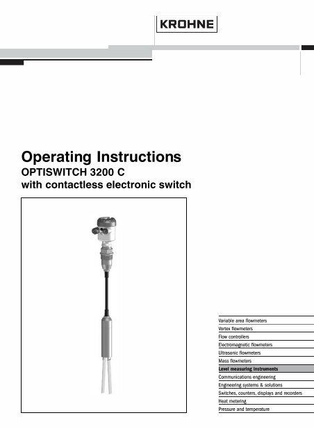
Operating Instructions<br />
OPTISWITCH <strong>3200</strong> C<br />
<strong>with</strong> contactless electronic switch
Contents<br />
Contents<br />
1 About this document<br />
1.1 Function ............................. 4<br />
1.2 Target group .......................... 4<br />
1.3 Symbolism used ....................... 4<br />
2 For your safety<br />
2.1 Authorised personnel .................... 5<br />
2.2 Appropriate use. ....................... 5<br />
2.3 Warning about misuse ................... 5<br />
2.4 CE conformity ......................... 5<br />
2.5 SIL conformity ......................... 6<br />
2.6 Safety instructions for Ex areas ............ 6<br />
3 Product description<br />
3.1 Configuration. ......................... 7<br />
3.2 Principle of operation. ................... 7<br />
3.3 Operation ............................ 9<br />
3.4 Storage and transport ................... 9<br />
4 Mounting<br />
4.1 General instructions. .................... 10<br />
4.2 Mounting instructions. ................... 11<br />
5 Connecting to voltage supply<br />
5.1 Preparing the connection ................. 16<br />
5.2 Connection steps. ...................... 16<br />
5.3 Wiring plan, single chamber housing. ........ 17<br />
6 Set up<br />
6.1 General. ............................. 20<br />
6.2 Adjustment elements .................... 20<br />
6.3 Function chart ......................... 21<br />
7 Maintenance and fault rectification<br />
7.1 Maintenance .......................... 23<br />
7.2 Rectify faults .......................... 23<br />
7.3 Exchange the electronics ................. 24<br />
7.4 Instrument repair ....................... 25<br />
8 Dismounting<br />
8.1 Dismounting procedure .................. 26<br />
8.2 Disposal ............................. 26<br />
2 OPTISWITCH <strong>3200</strong> C - <strong>with</strong> contactless electronic switch<br />
29956-EN-060830
Contents<br />
9 Supplement<br />
9.1 Technical data. ........................ 27<br />
9.2 Dimensions ........................... 30<br />
Supplementary operating instructions manuals<br />
Information:<br />
OPTISWITCH <strong>3200</strong> C is available in different versions.<br />
Depending on the selected version, supplementary operating<br />
instructions manuals may also come <strong>with</strong> the shipment. The<br />
supplementary operating instructions manuals are listed in<br />
section "Product description.<br />
29956-EN-060830<br />
Operating instructions manuals for accessories and<br />
replacement parts<br />
Tip:<br />
To ensure reliable setup and operation of your OPTISWITCH<br />
<strong>3200</strong> C, we offer accessories and replacement parts. The<br />
associated documents are:<br />
l<br />
l<br />
Operating instructions manual "Oscillator"<br />
Operating instructions manual "Cable shortening set"<br />
OPTISWITCH <strong>3200</strong> C - <strong>with</strong> contactless electronic switch 3
About this document<br />
1 About this document<br />
1.1 Function<br />
This operating instructions manual has all the information you<br />
need for quick setup and safe operation. Please read this<br />
manual before you start setup.<br />
1.2 Target group<br />
This operating instructions manual is directed to trained,<br />
qualified personnel. The contents of this manual should be<br />
made available to these personnel and put into practice by<br />
them.<br />
1.3 Symbolism used<br />
Information, tip, note<br />
This symbol indicates helpful additional information.<br />
Caution: If this warning is ignored, faults or<br />
malfunctions can result.<br />
Warning: If this warning is ignored, injury to persons and/or<br />
serious damage to the instrument can result.<br />
Danger: If this warning is ignored, serious injury to persons<br />
and/or destruction of the instrument can result.<br />
Ex applications<br />
This symbol indicates special instructions for Ex applications.<br />
l<br />
à<br />
List<br />
The dot set in front indicates a list <strong>with</strong> no implied sequence.<br />
Action<br />
This arrow indicates a single action.<br />
1 Sequence<br />
Numbers set in front indicate successive steps in a procedure.<br />
4 OPTISWITCH <strong>3200</strong> C - <strong>with</strong> contactless electronic switch<br />
29956-EN-060830
For your safety<br />
2 For your safety<br />
2.1 Authorised personnel<br />
All operations described in this operating instructions manual<br />
must be carried out only by trained specialist personnel<br />
authorised by the operator. For safety and warranty reasons,<br />
any internal work on the instruments must be carried out only<br />
by personnel authorised by the manufacturer.<br />
2.2 Appropriate use<br />
OPTISWITCH <strong>3200</strong> C is a sensor for level detection.<br />
Detailed information on the application range of OPTISWITCH<br />
<strong>3200</strong> C is available in chapter "Product description".<br />
2.3 Warning about misuse<br />
Inappropriate or incorrect use of the instrument can give rise to<br />
application-specific hazards, e.g. vessel overfill or damage to<br />
system components through incorrect mounting or adjustment.<br />
2.4 General safety instructions<br />
OPTISWITCH <strong>3200</strong> C is a high-tech instrument requiring the<br />
strict observance of standard regulations and guidelines. The<br />
user must take note of the safety instructions in this operating<br />
instructions manual, the country-specific installation standards<br />
(e.g. the VDE regulations in Germany) as well as all prevailing<br />
safety regulations and accident prevention rules.<br />
2.5 CE conformity<br />
OPTISWITCH <strong>3200</strong> C is in CE conformity <strong>with</strong> EMC (89/336/<br />
EWG), fulfils NAMUR recommendation NE 21 and is in CE<br />
conformity <strong>with</strong> LVD (73/23/EWG).<br />
Conformity has been judged according to the following<br />
standards:<br />
29956-EN-060830<br />
l<br />
EMC:<br />
- Emission EN 61326/A1: 1998 (class B)<br />
- Susceptibility EN 61326: 1997/A1:1998<br />
l LVD: EN 61010-1: 2001<br />
The instrument is designed for industrial use.<br />
OPTISWITCH <strong>3200</strong> C - <strong>with</strong> contactless electronic switch 5
For your safety<br />
2.6 SIL conformity<br />
OPTISWITCH <strong>3200</strong> C fulfills the requirements of functional<br />
safety according to IEC 61508/IEC 61511. You can find further<br />
information in the supplementary instructions manual "Safety<br />
Manual - Functional safety (SIL) OPTISWITCH 3XXX".<br />
2.7 Safety instructions for Ex areas<br />
Please note the Ex-specific safety information for installation<br />
and operation in Ex areas. These safety instructions are part of<br />
the operating instructions manual and come <strong>with</strong> the Exapproved<br />
instruments.<br />
6 OPTISWITCH <strong>3200</strong> C - <strong>with</strong> contactless electronic switch<br />
29956-EN-060830
Product description<br />
3 Product description<br />
3.1 Configuration<br />
Scope of delivery<br />
Components<br />
The scope of delivery encompasses:<br />
l<br />
l<br />
OPTISWITCH <strong>3200</strong> C level sensor<br />
Documentation<br />
- this operating instructions manual<br />
- Supplementary instructions manual "Plug connector for<br />
level sensors" (optional)<br />
- Ex specific safety instructions (<strong>with</strong> Ex versions), if<br />
necessary further certificates<br />
OPTISWITCH <strong>3200</strong> C consists of the following components:<br />
l<br />
l<br />
l<br />
Housing cover<br />
Housing <strong>with</strong> electronics<br />
process fitting <strong>with</strong> tuning fork<br />
1<br />
2<br />
3<br />
Fig. 1: OPTISWITCH <strong>3200</strong> C <strong>with</strong> plastic housing<br />
1 Housing cover<br />
2 Housing <strong>with</strong> electronics<br />
3 Process fitting<br />
3.2 Principle of operation<br />
29956-EN-060830<br />
Area of application<br />
OPTISWITCH <strong>3200</strong> C is a level sensor <strong>with</strong> tuning fork for level<br />
detection.<br />
OPTISWITCH <strong>3200</strong> C - <strong>with</strong> contactless electronic switch 7
Product description<br />
It is designed for industrial use in all areas of process<br />
technology and is preferably used for bulk solids.<br />
Typical applications are overfill and dry run protection. Thanks<br />
to its simple and robust measuring system, OPTISWITCH<br />
<strong>3200</strong> C is virtually unaffected by the chemical and physical<br />
properties of the bulk solid.<br />
It functions even when exposed to strong external vibration or<br />
changing products.<br />
Solid detection in water<br />
If OPTISWITCH <strong>3200</strong> C was ordered for detection of solids in<br />
water, the tuning fork is adjusted to the density of water. In the<br />
air or when covered by water (density: 1 g/cm³/0.036 lbs/in)<br />
OPTISWITCH <strong>3200</strong> C signals "uncovered". Only if the<br />
vibrating element is also covered <strong>with</strong> solids (e.g. sand,<br />
sludge, gravel etc.) will the sensor signal "covered".<br />
Fault monitoring<br />
The electronics of OPTISWITCH <strong>3200</strong> C continuously monitors<br />
the following criteria:<br />
l Correct vibrating frequency<br />
l Line break to the piezo drive<br />
If one of the stated malfunctions is detected or in case of<br />
power failure, the electronics takes on a defined switching<br />
condition, i.e. the contactless electronic switch opens (safe<br />
condition).<br />
Physical principle<br />
Power supply<br />
The tuning fork is piezoelectrically energised and vibrates at its<br />
mechanical resonance frequency of approx. 150 Hz. When the<br />
tuning fork is submerged in the product, the vibration<br />
amplitude changes. This change is detected by the integrated<br />
oscillator and converted into a switching command.<br />
OPTISWITCH <strong>3200</strong> C is a compact instrument, i.e. it can be<br />
operated <strong>with</strong>out external evaluation system. The integrated<br />
electronics evaluates the level signal and outputs a switching<br />
signal. With this switching signal, a connected device can be<br />
directly activated (e.g. a warning system, a PLC, a pump etc.).<br />
The exact range of the power supply is stated in the "Technical<br />
data" in the "Supplement".<br />
8 OPTISWITCH <strong>3200</strong> C - <strong>with</strong> contactless electronic switch<br />
29956-EN-060830
Product description<br />
3.3 Operation<br />
With the factory setting, products <strong>with</strong> a density of >0.02 g/cm³<br />
(>0.0008 lbs/in³) can be measured. The instrument can also<br />
be adapted to products <strong>with</strong> lower density >0.008 g/cm³<br />
(>0.0003 lbs/in³).<br />
On the electronics module you will find the following indicating<br />
and adjustment elements:<br />
l<br />
l<br />
l<br />
signal lamp for indication of the switching condition (green/<br />
red)<br />
potentiometer for adaptation to the product density<br />
Mode switch for selecting the switching condition (min./<br />
max.)<br />
3.4 Storage and transport<br />
Packaging<br />
Storage and transport temperature<br />
Your instrument was protected by packaging during transport.<br />
Its capacity to handle normal loads during transport is assured<br />
by a test according to DIN 55439.<br />
The packaging of standard instruments consists of environment-friendly,<br />
recyclable cardboard. In addition, the sensor is<br />
provided <strong>with</strong> a protective cover of cardboard. For special<br />
versions PE foam or PE foil is also used. Dispose of the<br />
packaging material via specialised recycling companies.<br />
l Storage and transport temperature see "Supplement -<br />
Technical data - Ambient conditions"<br />
l Relative humidity 20 … 85 %<br />
29956-EN-060830<br />
OPTISWITCH <strong>3200</strong> C - <strong>with</strong> contactless electronic switch 9
Mounting<br />
4 Mounting<br />
4.1 General instructions<br />
<strong>Switch</strong>ing point<br />
Moisture<br />
In general, OPTISWITCH <strong>3200</strong> C can be mounted in any<br />
position. The instrument must be mounted in such a way that<br />
the vibrating element is at the height of the requested switching<br />
point.<br />
Use the recommended cables (see chapter "Connecting to<br />
power supply") and tighten the cable gland.<br />
You can give your OPTISWITCH <strong>3200</strong> C additional protection<br />
against moisture penetration by leading the connection cable<br />
downward in front of the cable entry. Rain and condensation<br />
water can thus drain off. This applies mainly to mounting<br />
outdoors, in areas where moisture is expected (e.g. by<br />
cleaning processes) or on cooled or heated vessels.<br />
Fig. 2: Measures against moisture penetration<br />
Transport<br />
Do not hold OPTISWITCH <strong>3200</strong> C on the vibrating element.<br />
Especially <strong>with</strong> flange and tube versions, the sensor can be<br />
damaged by the weight of the instrument.<br />
Remove the protective cover just before mounting.<br />
Pressure/Vacuum<br />
The process fitting must be sealed if there is gauge or low<br />
pressure in the vessel. Before use, check if the seal material is<br />
resistant against the measured product and the process<br />
temperature.<br />
The max. permissible pressure is stated in the "Technical<br />
data" in the "Supplement" or on the type label of the sensor.<br />
10 OPTISWITCH <strong>3200</strong> C - <strong>with</strong> contactless electronic switch<br />
29956-EN-060830
Mounting<br />
Handling<br />
The vibrating level switch is a measuring instrument and must<br />
be treated accordingly. Bending the vibrating element will<br />
destroy the instrument.<br />
Warning:<br />
The housing must not be used to screw in the instrument!<br />
Applying tightening force on the housing can damage its<br />
internal mechanical parts.<br />
To screw in, use the hexagon above the thread.<br />
4.2 Mounting instructions<br />
Tensile load<br />
Material cone<br />
Make sure that the max. permissible tensile load of the<br />
suspension cable is not exceeded. The danger of this<br />
happening exists particularly <strong>with</strong> very heavy solids and large<br />
meas. lengths. The max. permissible load is stated under<br />
"Technical data" in the "Supplement".<br />
In silos for bulk solids, material cones can form and change the<br />
switching point. Please keep this in mind when installing the<br />
sensor in the vessel. We recommend selecting an installation<br />
location where the vibrating fork detects an average value of<br />
the material cone.<br />
The tuning fork must be mounted at a location that takes the<br />
arrangement of the filling and emptying apertures into account.<br />
To compensate measurement errors caused by the material<br />
cone in cylindrical vessels, the sensor must be mounted at a<br />
distance of d/6 from the vessel wall.<br />
29956-EN-060830<br />
OPTISWITCH <strong>3200</strong> C - <strong>with</strong> contactless electronic switch 11
Mounting<br />
d<br />
6<br />
d<br />
6<br />
d<br />
d<br />
Fig. 3: Filling and emptying centered<br />
1<br />
d<br />
6<br />
2<br />
d<br />
3<br />
Fig. 4: Filling in the center, emptying laterally<br />
1 OPTISWITCH <strong>3200</strong> C<br />
2 Emptying opening<br />
3 Filling opening<br />
12 OPTISWITCH <strong>3200</strong> C - <strong>with</strong> contactless electronic switch<br />
29956-EN-060830
Mounting<br />
Socket<br />
Inflowing medium<br />
The vibrating element should protrude into the vessel to avoid<br />
buildup. For that reason, avoid using mounting bosses for<br />
flanges and screwed fittings. This applies particularly to use<br />
<strong>with</strong> adhesive products.<br />
If OPTISWITCH <strong>3200</strong> C is mounted in the filling stream,<br />
unwanted switching signals may be generated. Mount OPTI-<br />
SWITCH <strong>3200</strong> C at a location in the vessel where no disturbing<br />
influence from e.g. filling openings, agitators etc. can occur.<br />
Fig. 5: Inflowing medium<br />
Flows<br />
To minimise flow resistance caused by the tuning fork,<br />
OPTISWITCH <strong>3200</strong> C should be mounted in such a way that<br />
the surfaces of the blades are parallel to the product<br />
movement.<br />
29956-EN-060830<br />
OPTISWITCH <strong>3200</strong> C - <strong>with</strong> contactless electronic switch 13
Mounting<br />
1<br />
2<br />
Fig. 6: Orientation of the tuning fork in case of flow<br />
1 Marking <strong>with</strong> screwed version<br />
2 Direction of flow<br />
Baffle protection against falling<br />
rocks<br />
In applications such as grit chambers or settling basins for<br />
coarse sediments, the vibrating element must be protected<br />
against damage <strong>with</strong> a suitable baffle.<br />
This baffle must be manufactured by you.<br />
14 OPTISWITCH <strong>3200</strong> C - <strong>with</strong> contactless electronic switch<br />
29956-EN-060830
Mounting<br />
>125<br />
Fig. 7: Baffle protection against damages<br />
29956-EN-060830<br />
OPTISWITCH <strong>3200</strong> C - <strong>with</strong> contactless electronic switch 15
Connecting to voltage supply<br />
5 Connecting to voltage supply<br />
5.1 Preparing the connection<br />
Note safety instructions<br />
Take note of safety<br />
instructions for Ex<br />
applications<br />
Select power supply<br />
Selecting the connection cable<br />
Generally not the following safety instructions:<br />
l<br />
Connect only in the complete absence of line voltage<br />
In hazardous areas you should take note of the appropriate<br />
regulations, conformity and type approval certificates of the<br />
sensors and power supply units.<br />
Connect the power supply according to the following diagrams.<br />
Oscillator WE60C is designed in protection class 1. To<br />
maintain this protection class, it is absolutely necessary that<br />
the ground conductor be connected to the internal ground<br />
terminal. Take note of the general installation regulations. As a<br />
rule, connect OPTISWITCH <strong>3200</strong> C to vessel ground (PA), or<br />
in case of plastic vessels, to the next ground potential. On the<br />
side of the housing there is a ground terminal between the<br />
cable entries. This connection serves to drain off electrostatic<br />
charges. In Ex applications, the installation regulations for<br />
hazardous areas must be given priority.<br />
The data for power supply are stated in the "Technical data" in<br />
the "Supplement".<br />
OPTISWITCH <strong>3200</strong> C is connected <strong>with</strong> standard cable <strong>with</strong><br />
round cross-section. An outer cable diameter of 5 … 9 mm<br />
(0.2 … 0.35 in) ensures the seal effect of the cable entry.<br />
If cable <strong>with</strong> a different diameter or wire cross section is used,<br />
exchange the seal or use an appropriate cable connection.<br />
In hazardous areas, only use approved cable connections for<br />
OPTISWITCH <strong>3200</strong> C.<br />
Select connection<br />
cable for Ex applications<br />
Take note of the corresponding installation regulations for Ex<br />
applications.<br />
5.2 Connection steps<br />
With Ex instruments, the housing cover may only be opened if<br />
there is no explosive atmosphere present.<br />
Proceed as follows:<br />
16 OPTISWITCH <strong>3200</strong> C - <strong>with</strong> contactless electronic switch<br />
29956-EN-060830
Connecting to voltage supply<br />
1 Unscrew the housing cover<br />
2 Loosen compression nut of the cable entry<br />
3 Remove approx. 10 cm (4 in) of the cable mantle, strip<br />
approx. 1 cm (0.4 in) insulation from the ends of the<br />
individual wires<br />
4 Insert the cable into the sensor through the cable entry<br />
5 Lift the opening levers of the terminals <strong>with</strong> a screwdriver<br />
(see following illustration)<br />
6 Insert the wire ends into the open terminals according to<br />
the wiring plan<br />
7 Press the opening lever of the terminals downward, you will<br />
hear the terminal spring closing<br />
8 Check the hold of the wires in the terminals by lightly<br />
pulling on them<br />
9 Tighten the compression nut of the cable entry, the seal<br />
ring must completely encircle the cable<br />
10 If necessary, carry out a fresh adjustment<br />
11 Screw the housing cover back on<br />
The electrical connection is hence finished.<br />
Fig. 8: Connection steps 5 and 6<br />
5.3 Wiring plan, single chamber housing<br />
29956-EN-060830<br />
The following illustrations apply to the non-Ex as well as to the<br />
EEx d version.<br />
OPTISWITCH <strong>3200</strong> C - <strong>with</strong> contactless electronic switch 17
Connecting to voltage supply<br />
Housing overview<br />
4<br />
4<br />
4<br />
1<br />
2 3<br />
Fig. 9: Material versions, single chamber housing<br />
1 Plastic (not <strong>with</strong> EEx d)<br />
2 Aluminium<br />
3 Stainless steel (not <strong>with</strong> EEx d)<br />
4 Filter element for pressure compensation (not <strong>with</strong> EEx d)<br />
Electronics and connection<br />
compartment<br />
1<br />
5<br />
2<br />
4<br />
3<br />
Wiring plan<br />
Fig. 10: Electronics and connection compartment<br />
1 Potentiometer for switching point adaptation (covered)<br />
2 DIL switch for mode adjustment<br />
3 Ground terminal<br />
4 Screwed terminals<br />
5 Control lamp<br />
We recommend connecting OPTISWITCH <strong>3200</strong> C in such a<br />
way that the switching circuit is open when there is a level<br />
signal, line break or failure (safe condition).<br />
The contactless electronic switch is always shown in nonoperative<br />
condition.<br />
The instrument is used for direct control of relays, contactors,<br />
magnet valves, warning lights, horns etc. It must not be<br />
operated <strong>with</strong>out an intermediately connected load, because<br />
18 OPTISWITCH <strong>3200</strong> C - <strong>with</strong> contactless electronic switch<br />
29956-EN-060830
Connecting to voltage supply<br />
the electronics would be destroyed if connected directly to the<br />
mains. It is not suitable for connection to low voltage PLC<br />
inputs.<br />
Domestic current is temporarily lowered below 1 mA after<br />
switching off the load so that contactors, whose holding current<br />
is lower than the constant domestic current of the electronics,<br />
are reliably switched off.<br />
1<br />
Fig. 11: Wiring plan<br />
1 Screen<br />
29956-EN-060830<br />
OPTISWITCH <strong>3200</strong> C - <strong>with</strong> contactless electronic switch 19
Set up<br />
6 Set up<br />
6.1 General<br />
The numbers in brackets refer to the following illustrations.<br />
Function/Configuration<br />
On the electronics module you will find the following indicating<br />
and adjustment elements:<br />
l Potentiometer for switching point adaptation (1)<br />
l DIL switch for mode adjustment - min./max. (2)<br />
l Signal lamp (5)<br />
Note:<br />
As a rule, always set the mode <strong>with</strong> mode switch (2) before<br />
starting the setup of OPTISWITCH <strong>3200</strong> C. The switching<br />
output will change if you set the mode switch (2) afterwards.<br />
This could possibly trigger other connected instruments or<br />
devices.<br />
6.2 Adjustment elements<br />
5<br />
1<br />
2<br />
4<br />
3<br />
Fig. 12: Oscillator WE60C - Contactless electronic switch<br />
1 Potentiometer for switching point adaptation<br />
2 DIL switch for mode adjustment<br />
3 Ground terminal<br />
4 Screwed terminals<br />
5 Control lamp<br />
20 OPTISWITCH <strong>3200</strong> C - <strong>with</strong> contactless electronic switch<br />
29956-EN-060830
Set up<br />
<strong>Switch</strong>ing point adaptation (1)<br />
Mode adjustment (2)<br />
Signal lamp (5)<br />
With the potentiometer you can adapt the switching point to the<br />
solid. It is already preset and must only be modified in special<br />
cases.<br />
By default, the potentiometer of OPTISWITCH <strong>3200</strong> C is set to<br />
the right stop (>0.02 g/cm³ or >0.0008 lbs/in³). In case of very<br />
light-weight solids, turn the potentiometer to the left stop<br />
(>0.008 g/cm³ or >0.0003 lbs/in³). OPTISWITCH <strong>3200</strong> C will<br />
thus be more sensitive and can detect light-weight solids more<br />
reliably.<br />
For instruments detecting solids in water, these values are not<br />
applicable. The potentiometer is preset and must not be<br />
changed.<br />
With the mode adjustment (min./max.) you can change the<br />
switching condition of the output. You can set the required<br />
mode acc. to the "Function chart" (max. -max. detection or<br />
overfill protection, min. -min. detection or dry run protection).<br />
We recommend connecting acc. to the quiescent current<br />
principle (contactless electronic switch is open when the<br />
switching point is reached) because the contactless electronic<br />
switch takes on the same (safe) condition if a failure is<br />
detected.<br />
Control lamp for indication of the switching condition.<br />
l<br />
l<br />
l<br />
green = switch closed<br />
red = switch open<br />
red (flashing) = failure<br />
6.3 Function chart<br />
The following chart provides an overview of the switching<br />
conditions depending on the adjusted mode and level.<br />
Mode max.<br />
Overfill protection<br />
<strong>Level</strong> <strong>Switch</strong>ing status Control lamp<br />
1<br />
2<br />
Mode max.<br />
Overfill protection<br />
<strong>Switch</strong> closed<br />
Green<br />
29956-EN-060830<br />
1 2<br />
<strong>Switch</strong> open<br />
red<br />
OPTISWITCH <strong>3200</strong> C - <strong>with</strong> contactless electronic switch 21
Set up<br />
Mode min.<br />
Dry run protection<br />
<strong>Level</strong> <strong>Switch</strong>ing status Control lamp<br />
1<br />
2<br />
Mode min.<br />
Dry run protection<br />
<strong>Switch</strong> closed<br />
Green<br />
1<br />
2<br />
Failure of the supply voltage<br />
(min./max. mode)<br />
any<br />
<strong>Switch</strong> open<br />
red<br />
1<br />
2<br />
<strong>Switch</strong> open<br />
Failure<br />
any<br />
1<br />
2<br />
<strong>Switch</strong> open<br />
flashes red<br />
22 OPTISWITCH <strong>3200</strong> C - <strong>with</strong> contactless electronic switch<br />
29956-EN-060830
Maintenance and fault rectification<br />
7 Maintenance and fault rectification<br />
7.1 Maintenance<br />
When used as directed in normal operation, OPTISWITCH<br />
<strong>3200</strong> C is completely maintenance free.<br />
7.2 Rectify faults<br />
Causes of malfunction<br />
Fault rectification<br />
OPTISWITCH <strong>3200</strong> C offers maximum reliability. Nevertheless<br />
faults can occur during operation. These may be caused by the<br />
following, e.g.:<br />
l Sensor<br />
l Process<br />
l Power supply<br />
l Signal processing<br />
The first measure to be taken is to check the output signal. In<br />
many cases, the causes can be determined this way and the<br />
faults rectified.<br />
29956-EN-060830<br />
Checking the switching signal<br />
? OPTISWITCH <strong>3200</strong> C signals "covered" when the vibrating<br />
element is not submerged (overfill protection)<br />
? OPTISWITCH <strong>3200</strong> C signals "uncovered" when the<br />
vibrating element is submerged (dry run protection)<br />
l Supply voltage too low<br />
à Check the power supply<br />
l Electronics defective<br />
à Press the mode switch (min./max.). If the instrument<br />
then changes the mode, the instrument may be<br />
mechanically damaged. Should the switching function<br />
in the correct mode still be faulty, return the instrument<br />
for repair.<br />
à Push the mode switch. If the instrument then does not<br />
change the mode, the oscillator may be defective.<br />
Exchange the oscillator.<br />
à Check if there is buildup on the vibrating element, and if<br />
so, remove it.<br />
l Unfavourable installation location<br />
à Mount the instrument at a location in the vessel where<br />
no dead zones or mounds can form.<br />
à Check if the vibrating element is covered by buildup on<br />
the socket.<br />
OPTISWITCH <strong>3200</strong> C - <strong>with</strong> contactless electronic switch 23
Maintenance and fault rectification<br />
l Wrong mode selected<br />
à Set the correct mode on the mode switch (max.: overfill<br />
protection; min.: dry run protection). Wiring should be<br />
carried out according to the quiescent current principle.<br />
? Signal lamp flashes red<br />
l Electronics has detected a failure<br />
à Exchange instrument or return instrument for repair<br />
7.3 Exchange the electronics<br />
In general, all oscillators of series WE60 can be interchanged.<br />
If you want to use an oscillator <strong>with</strong> a different signal output,<br />
you can download the corresponding operating instructions<br />
manual from our homepage under Downloads.<br />
With EEx d instruments, the housing cover must only be<br />
opened if there is no explosive atmosphere.<br />
Proceed as follows:<br />
1 <strong>Switch</strong> off power supply<br />
2 Unscrew the housing cover<br />
3 Lift the opening levers of the terminals <strong>with</strong> a screwdriver<br />
4 Pull the connection cables out of the terminals<br />
5 Loosen the two screws <strong>with</strong> a screw driver (Torx size T10<br />
or slot 4)<br />
1<br />
2<br />
Fig. 13: Loosen the screws<br />
1 Electronics module<br />
2 Screws (2 pcs.)<br />
24 OPTISWITCH <strong>3200</strong> C - <strong>with</strong> contactless electronic switch<br />
29956-EN-060830
Maintenance and fault rectification<br />
6 Remove the old oscillator<br />
7 Compare the new oscillator <strong>with</strong> the old one. The type label<br />
of the oscillator must correspond to that of the old<br />
oscillator. This applies particularly to instruments used in<br />
hazardous areas.<br />
8 Compare the settings of the two oscillators. Set the<br />
adjustment elements of the new oscillator to the same<br />
setting of the old one.<br />
Information:<br />
Make sure that the housing is not rotated during the electronics<br />
exchange. Otherwise the plug may be in a different position<br />
later.<br />
9 Insert the oscillator carefully. Make sure that the plug is in<br />
the correct position.<br />
10 Tighten the two screws <strong>with</strong> a screwdriver (Torx size T10<br />
or slot 4).<br />
11 Insert the wire ends into the open terminals according to<br />
the wiring plan<br />
12 Press the opening lever of the terminals downward, you will<br />
hear the terminal spring closing<br />
13 Check the hold of the wires in the terminals by lightly<br />
pulling on them<br />
14 Check the tightness of the cable entry. The seal ring must<br />
completely encircle the cable.<br />
15 Screw the housing cover back on<br />
The electronics exchange is now finished.<br />
29956-EN-060830<br />
7.4 Instrument repair<br />
If a repair is necessary, please proceed as follows:<br />
You can download a return form from our website http://www.<br />
krohne-mar.com/fileadmin/media-lounge/PDF-Download/<br />
Specimen_e.pdf.<br />
By doing this you help us carry out the repair quickly and<br />
<strong>with</strong>out having to call back for needed information.<br />
l<br />
l<br />
l<br />
Print and fill out one form per instrument<br />
Clean the instrument and pack it damage-proof<br />
Attach the completed form and possibly also a safety data<br />
sheet to the instrument<br />
OPTISWITCH <strong>3200</strong> C - <strong>with</strong> contactless electronic switch 25
Dismounting<br />
8 Dismounting<br />
8.1 Dismounting procedure<br />
Warning:<br />
Before dismounting, be aware of dangerous process conditions<br />
such as e.g. pressure in the vessel, high temperatures,<br />
corrosive or toxic products etc.<br />
Take note of chapters "Mounting" and "Connecting to power<br />
supply" and carry out the listed steps in reverse order.<br />
With Ex instruments, the housing cover may only be opened if<br />
there is no explosive atmosphere present.<br />
8.2 Disposal<br />
The instrument consists of materials which can be recycled by<br />
specialised recycling companies. We use recyclable materials<br />
and have designed the electronic modules to be easily<br />
separable.<br />
WEEE directive 2002/96/EG<br />
This instrument is not subject to the WEEE directive 2002/96/<br />
EG and the respective national laws (in Germany, e.g.<br />
ElektroG). Pass the instrument directly on to a specialised<br />
recycling company and do not use the municipal collecting<br />
points. These may be used only for privately used products<br />
according to the WEEE directive.<br />
Correct disposal avoids negative effects to persons and<br />
environment and ensures recycling of useful raw materials.<br />
Materials: see "Technical data"<br />
If you cannot dispose of the instrument properly, please<br />
contact us about disposal methods or return.<br />
26 OPTISWITCH <strong>3200</strong> C - <strong>with</strong> contactless electronic switch<br />
29956-EN-060830
Supplement<br />
9 Supplement<br />
9.1 Technical data<br />
General data<br />
Material 316L corresponds to 1.4404 or 1.4435<br />
Materials, wetted parts<br />
- Process fitting - thread 316L<br />
- Process fitting - flange 316L<br />
- Process seal Klingersil C-4400<br />
- Seal (vibrating element) CR, CSM<br />
- Tuning fork 316L<br />
- Suspension cable PUR<br />
Materials, non-wetted parts<br />
- Housing Plastic PBT (Polyester), Alu die-casting powder-coated,<br />
316L<br />
- Seal ring between housing and<br />
housing cover<br />
- Ground terminal 316L<br />
Weight<br />
- <strong>with</strong> plastic housing 1500 g (53 oz)<br />
- <strong>with</strong> Aluminium housing 1950 g (69 oz)<br />
- <strong>with</strong> stainless steel housing 2300 g (81 oz)<br />
- Suspension cable 165 g/m (1.8 oz/ft)<br />
NBR (stainless steel housing), silicone (Alu/<br />
plastic housing)<br />
Max. permissible tensile load<br />
Sensor length<br />
3000 N (675 lbs)<br />
0.3 … 80 m (1 … 262 ft)<br />
Output variable<br />
Output<br />
Contactless electronic switch<br />
Modes (adjustable)<br />
min./max.<br />
Integration time<br />
- when immersed approx. 0.5 s<br />
- when laid bare approx. 1 s<br />
29956-EN-060830<br />
Ambient conditions<br />
Ambient temperature on the housing -40 … +80 °C (-40 … +176 °F)<br />
Storage and transport temperature<br />
-40 … +80 °C (-40 … +176 °F)<br />
OPTISWITCH <strong>3200</strong> C - <strong>with</strong> contactless electronic switch 27
Supplement<br />
Process conditions<br />
Parameter<br />
Limit level of solids<br />
Process pressure<br />
-1 … 6 bar/-100 … 600 kPa (-14.5 … 87 psi)<br />
OPTISWITCH <strong>3200</strong> C of 316L<br />
-20 … +80 °C (-4 … +176 °F)<br />
Density<br />
- Standard >0.02 g/cm³ (0.0007 lbs/in³)<br />
- adjustable >0.008 g/cm³ (0.0003 lbs/in³)<br />
Electromechanical data<br />
Cable entry/plug (dependent on the version)<br />
- Single chamber housing l 1x cable entry M20x1.5 (cable-ø 5 … 9 mm),<br />
1x blind stopper M20x1.5, attached 1x<br />
cable entry M20x1.5<br />
or:<br />
l 1x cable entry ½ NPT, 1x blind stopper<br />
½ NPT, 1x cable entry ½ NPT<br />
or:<br />
Spring-loaded terminals<br />
l<br />
1x plug M12x1, 1x blind stopper M20x1.5<br />
for wire cross-section up to 1.5 mm²<br />
(0.0023 in²)<br />
Adjustment elements<br />
Mode switch<br />
- min. Min. detection or dry run protection<br />
- max. Max. detection or overfill protection<br />
Voltage supply<br />
Supply voltage<br />
20 … 253 VAC, 50/60 Hz, 20 … 253 VDC<br />
Domestic current requirement<br />
approx. 3 mA (via load circuit)<br />
Load current<br />
- min. 10 mA<br />
- max. 400 mA (at I >300 mA the ambient temperature<br />
can be max. 60 °C/140 °F) max. 4 A up to<br />
40 ms<br />
Electrical protective measures<br />
Protection IP 66/IP 67<br />
Overvoltage category<br />
III<br />
28 OPTISWITCH <strong>3200</strong> C - <strong>with</strong> contactless electronic switch<br />
29956-EN-060830
Supplement<br />
Protection class<br />
I<br />
Approvals 1)<br />
ATEX II 1/2G, 2G EExd d IIC T6<br />
ATEX II 1/2 DIP66 T<br />
29956-EN-060830<br />
1)<br />
Deviating data in Ex applications: see separate safety instructions.<br />
OPTISWITCH <strong>3200</strong> C - <strong>with</strong> contactless electronic switch 29
Supplement<br />
9.2 Dimensions<br />
OPTISWITCH <strong>3200</strong> C<br />
~ 69mm<br />
(2 23/ 32") ø 77mm<br />
(3 1/ 32")<br />
~ 69mm<br />
(2 23/ 32")<br />
ø 77mm<br />
(3 1/ 32")<br />
~ 116mm<br />
(4 9/ 16")<br />
ø 84mm<br />
(3 5/ 16")<br />
112mm<br />
(4 13/32")<br />
117mm<br />
(4 39/64")<br />
114mm<br />
(4 31/64")<br />
½<br />
M20x1,5/<br />
½ NPT<br />
M20x1,5/<br />
½ NPT<br />
M20x1,5<br />
1 2 3<br />
Fig. 14: Housing versions<br />
1 Plastic housing<br />
2 Stainless steel housing<br />
3 Aluminium housing<br />
30 OPTISWITCH <strong>3200</strong> C - <strong>with</strong> contactless electronic switch<br />
29956-EN-060830
Supplement<br />
150mm (5 29/32")<br />
L<br />
22mm<br />
(55/64")<br />
33mm<br />
(1 19/64")<br />
G1½A<br />
ø 43mm (1 11/ 16 ")<br />
ø 11mm (7/ 16 ")<br />
160mm (6 19/64")<br />
ø 43mm (1 11/ 16 ")<br />
29956-EN-060830<br />
Fig. 15: OPTISWITCH <strong>3200</strong> C, threaded version G1½ A<br />
L = Sensor length, see "Technical data"<br />
OPTISWITCH <strong>3200</strong> C - <strong>with</strong> contactless electronic switch 31
Supplement<br />
32 OPTISWITCH <strong>3200</strong> C - <strong>with</strong> contactless electronic switch<br />
29956-EN-060830
Supplement<br />
29956-EN-060830<br />
OPTISWITCH <strong>3200</strong> C - <strong>with</strong> contactless electronic switch 33
Supplement<br />
34 OPTISWITCH <strong>3200</strong> C - <strong>with</strong> contactless electronic switch<br />
29956-EN-060830
Supplement<br />
29956-EN-060830<br />
OPTISWITCH <strong>3200</strong> C - <strong>with</strong> contactless electronic switch 35
Subject to change <strong>with</strong>out notice<br />
29956-EN-060830