3DS SIMULIA Community News - Dassault Systèmes
3DS SIMULIA Community News - Dassault Systèmes
3DS SIMULIA Community News - Dassault Systèmes

You also want an ePaper? Increase the reach of your titles
YUMPU automatically turns print PDFs into web optimized ePapers that Google loves.
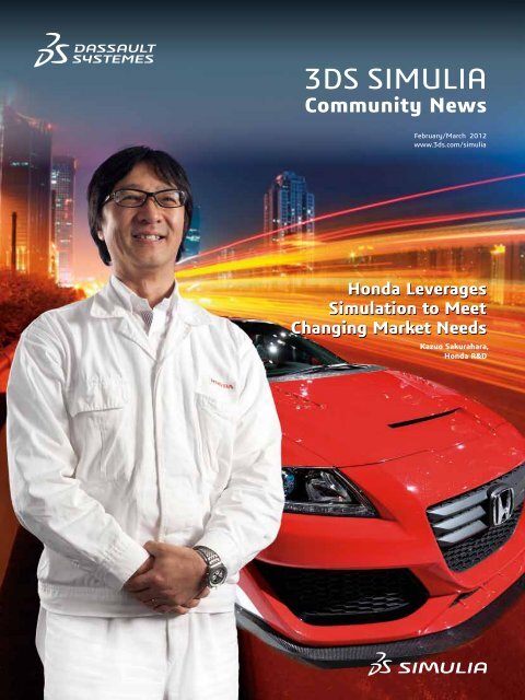
<strong>3DS</strong> <strong>SIMULIA</strong><br />
<strong>Community</strong> <strong>News</strong><br />
February/March 2012<br />
www.3ds.com/simulia<br />
Honda Leverages<br />
Simulation to Meet<br />
Changing Market Needs<br />
Kazuo Sakurahara,<br />
Honda R&D
<strong>3DS</strong> <strong>SIMULIA</strong><br />
<strong>Community</strong> <strong>News</strong><br />
February/March 2012<br />
www.3ds.com/simulia<br />
Inside This Issue<br />
12 Cover Story<br />
Honda Leverages Simulation to<br />
Meet Changing Market Needs<br />
On the cover: Kazuo Sakurahara<br />
16 Customer Case Study<br />
Hyundai Motor Company Performs<br />
Faster, Integrated Design Simulations<br />
with Abaqus Unified FEA<br />
In Each Issue<br />
3 Executive Letter<br />
Scott Berkey, Chief Executive Officer, <strong>3DS</strong> <strong>SIMULIA</strong><br />
4 Customer Viewpoint<br />
MAHLE Powertrain is Driving Towards the<br />
Sustainable Car Engine of the Future<br />
6 Customer Spotlight<br />
Ford Motor Company Accelerates Design for<br />
Manufacturability of Conical Joints<br />
8 Strategy Overview<br />
Marc Schrank, Technical Marketing Director,<br />
Transportation & Mobility, <strong>3DS</strong> <strong>SIMULIA</strong><br />
11 Alliances<br />
• Wolf Star Technologies<br />
• Digital Product Simulation<br />
14 Product Update<br />
• Isight and <strong>3DS</strong> <strong>SIMULIA</strong> Execution Engine<br />
• <strong>3DS</strong> <strong>SIMULIA</strong> Version 6 2012x<br />
18 Customer Case Study<br />
Caltech Designs Self-Deploying Composite<br />
Booms for Satellites<br />
<strong>3DS</strong> <strong>SIMULIA</strong> <strong>Community</strong> <strong>News</strong><br />
is published by<br />
<strong>Dassault</strong> <strong>Systèmes</strong> Simulia Corp.<br />
Rising Sun Mills<br />
166 Valley Street<br />
Providence, RI 02909-2499<br />
Tel. +1 401 276 4400<br />
Fax. +1 401 276 4408<br />
simulia.info@3ds.com<br />
www.3ds.com/simulia<br />
Editor<br />
Karen Curtis<br />
Associate Editors<br />
Rachel Callery<br />
Tim Webb<br />
Contributors<br />
Kazuo Sakurahara (Honda),<br />
Mark Stephenson (MAHLE),<br />
Sungjin Yoon (Hyundai),<br />
Satyendra Savanur (Ford),<br />
Chinthaka Mallikarachchi (Caltech),<br />
Jeff Tippmann (UCSD),<br />
Martha Patricia Guerrero (UANL),<br />
Tim Hunter (Wolf Star Technologies),<br />
Anne Ribeiro (Digital Product<br />
Simulation), Parker Group,<br />
Scott Berkey, Marc Schrank,<br />
Matt Ladzinski, Jill DaPonte<br />
(<strong>3DS</strong> <strong>SIMULIA</strong>)<br />
Graphic Designer<br />
Todd Sabelli<br />
The <strong>3DS</strong> logo, <strong>SIMULIA</strong>, CATIA, 3DVIA,<br />
DELMIA, ENOVIA, EXALEAD, SolidWorks,<br />
Abaqus, Isight, and Unified FEA are<br />
trademarks or registered trademarks of<br />
<strong>Dassault</strong> <strong>Systèmes</strong> or its subsidiaries<br />
in the US and/or other countries. Other<br />
company, product, and service names may<br />
be trademarks or service marks of their<br />
respective owners. Copyright <strong>Dassault</strong><br />
<strong>Systèmes</strong>, 2012.<br />
20 Academic Update<br />
University of California at San Diego<br />
Analyzes Hail Ice Impact<br />
Universidad Autonoma de Nuevo Leon<br />
Simulates Vibrations in a Catalytic Converter<br />
22 Tips & Tricks<br />
How to Perform Simple and Quick<br />
Design Studies Using Execution<br />
History Data in Isight<br />
23 <strong>News</strong> and Events<br />
• 2012 <strong>3DS</strong> <strong>SIMULIA</strong> <strong>Community</strong> Conference<br />
• New Technology Briefs<br />
• Join the <strong>3DS</strong> <strong>SIMULIA</strong> Learning <strong>Community</strong><br />
MAR_SCN_Y12_VOL 2
Executive Letter<br />
“Twenty years from now you<br />
will be more disappointed by<br />
the things you didn’t do than<br />
by the ones you did. So throw<br />
off the bowlines. Sail away<br />
from the safe harbor. Catch<br />
the trade winds in your sails.<br />
Explore. Dream. Discover.”<br />
—Mark Twain<br />
3D Experience, a Catalyst for Innovation<br />
Ifeel that this quote from Mark Twain captures the essence of the evolution of our <strong>3DS</strong><br />
<strong>SIMULIA</strong> brand promise to our user community. Since our inception in 1978, we<br />
have been committed to enhancing and expanding the technical capabilities of realistic<br />
simulation solutions so that our global user community can explore physical behavior,<br />
discover paths to innovation, and collaborate on improving product performance in<br />
life and nature. During the last 34 years, <strong>3DS</strong> <strong>SIMULIA</strong> has expanded significantly,<br />
yet we have stayed on course with our strategy to deliver not only robust simulation<br />
technology, but equally high-quality services and support to every customer.<br />
As part of our strategic commitment to our user community, we have changed the<br />
name of this publication to <strong>3DS</strong> <strong>SIMULIA</strong> <strong>Community</strong> <strong>News</strong> (SCN). This change<br />
reflects, not only our focus on interacting with our global user community, but it also<br />
recognizes the contribution of our users in pushing the boundaries of our technology to<br />
solve challenging engineering problems.<br />
I am personally inspired by the papers and case studies provided by our community<br />
and extremely pleased to have the interview from Honda Motor Company as our<br />
cover story (page 12). Honda is a pioneer and major industry influence in utilizing <strong>3DS</strong><br />
<strong>SIMULIA</strong> technology. While many of the stories in this issue have an automotive focus,<br />
we are also providing real business value across a wide spectrum of industries.<br />
We are energized by the opportunity to take the next step in our brand's journey as<br />
an integral part of <strong>Dassault</strong> <strong>Systèmes</strong>’ 3D Experience platform. The 3D Experience<br />
platform transforms the way “innovators will innovate with consumers” by connecting<br />
designers, engineers, marketing managers and even consumers, in a new ‘social<br />
enterprise’. The combined technology and experience of our sister brands—<strong>3DS</strong><br />
CATIA, <strong>3DS</strong> SolidWorks, <strong>3DS</strong> DELMIA, <strong>3DS</strong> ENOVIA, <strong>3DS</strong> Exalead, <strong>3DS</strong> <strong>3DS</strong>wYm,<br />
<strong>3DS</strong> 3DVIA, and <strong>3DS</strong> Netvibes—offer significant value to you and your organizations.<br />
We believe that the integration of our proven, robust realistic simulation technology<br />
into a 3D Experience platform will indeed be a catalyst for innovation, enabling any<br />
enterprise stakeholder to participate in simulation driven decision-making processes<br />
resulting in a competitive advantage for you and your organization.<br />
To learn more about the evolution of <strong>3DS</strong> <strong>SIMULIA</strong> and <strong>Dassault</strong> <strong>Systèmes</strong>’ 3D<br />
Experience platform, I invite you to attend the 2012 <strong>3DS</strong> <strong>SIMULIA</strong> <strong>Community</strong><br />
Conference (SCC). Bernard Charlès, CEO of <strong>Dassault</strong> <strong>Systèmes</strong>, will share our<br />
company’s overarching vision and mission in relation to the <strong>3DS</strong> <strong>SIMULIA</strong> community.<br />
The 2012 SCC also features more than 80 user presentations providing you with a<br />
wealth of information.<br />
I look forward to meeting with you to learn more about your requirements and share<br />
insights into our ongoing commitment to delivering innovative simulation technology<br />
and high-quality support that will enable each of you to be a catalyst for innovation.<br />
Scott Berkey<br />
Chief Executive Officer<br />
<strong>3DS</strong> <strong>SIMULIA</strong> <strong>Community</strong> <strong>News</strong> February/March 2012<br />
3
Customer Viewpoint<br />
Driving Towards<br />
the Sustainable<br />
Car Engine of the Future<br />
By Mark Stephenson, MAHLE Powertrain Ltd.<br />
Stricter standards for fuel consumption<br />
and emissions are leading all of us<br />
in the automotive industry to go beyond<br />
what we have done in the past. At<br />
MAHLE Powertrain Ltd., for instance, our<br />
R&D effort now includes both extremedownsized<br />
internal combustion engines<br />
and range extenders for electric vehicles.<br />
Yet pushing the creative envelope in such<br />
new areas can bring its share of design<br />
challenges.<br />
As a Tier 1 automotive supplier that<br />
designs and develops engines, MAHLE<br />
must always meet the expectations<br />
of our OEM customers. We do this<br />
while balancing a variety of tradeoffs<br />
such as the underlying regulatory, cost,<br />
production, and business hurdles of<br />
weight, durability, friction, emissions, and<br />
efficiency. Plus, we have to meet timeto-market<br />
demands. Our go-to toolset in<br />
balancing all of these targets efficiently is<br />
computer-aided engineering (CAE), the<br />
main design driver that underscores our<br />
entire development process.<br />
Simulation up front<br />
We start every product development<br />
program with a cycle simulation<br />
to determine exactly what engine<br />
configuration and technology our<br />
customers are looking for. Moving to<br />
CAD, we turn to concept-level models for<br />
information on package volume, costs,<br />
and weight. Once a concept is chosen,<br />
we manage the models using Product<br />
Lifecycle Management (PLM). For fluid<br />
studies, we utilize several 1-D tools to<br />
help avoid and reduce pressure losses<br />
in the oil and cooling systems. To guide<br />
design of the combustion chamber and<br />
related systems, we employ Computational<br />
Fluid Dynamics (CFD) for insight into very<br />
complex 3-D behavior.<br />
We incorporate structural analysis of<br />
our conceptual ideas early on in the<br />
Figure 1. The 3-cylinder design for MAHLE’s downsized engine (shown here in cross section on left) generates<br />
the power of a 6-cylinder engine, necessitating the need for structural and thermal optimization (right) to ensure<br />
that the engine can sustain the stresses of running at higher loads.<br />
MAHLE Powertrain’s 3-cylinder, 1.2 liter,<br />
extreme-downsized, demonstration engine<br />
(I3) has been installed in two VW Passats for<br />
test driving. The 50-percent downsized unit<br />
generates 160 hp, gets 49 UK-miles-per-gallon,<br />
meets EU6 CO 2<br />
standards, has CO 2<br />
emissions of<br />
only 135 g/km, and was designed with the aid of<br />
an extensive suite of simulation software tools.<br />
development process, using Abaqus<br />
Finite Element Analysis (FEA) as the<br />
main workhorse for our thermal and<br />
stress queries. These studies help us<br />
investigate ways to reduce weight and<br />
friction of components, such as the crank<br />
train, connecting rods, bearing panel,<br />
and bearings. For preprocessing, fatigue<br />
analysis, and crank train dynamics, we are<br />
able to couple other tools seamlessly with<br />
Abaqus without worrying about integration,<br />
as they can all use or generate native<br />
Abaqus data.<br />
Each tool in our extensive library of<br />
software is hand-picked for its specific<br />
complementary capabilities, and our<br />
team of designers and analysts is crosstrained<br />
for maximum flexibility. Our design<br />
engineers are capable of using numerous<br />
CAD programs—virtually whatever our<br />
customer uses.<br />
Meeting the performance and<br />
efficiency challenge<br />
In our downsized engine program (which<br />
started about four years ago), if fuel<br />
efficiency had been the only engineering<br />
challenge, finding solutions would have<br />
been much simpler. But car buyers<br />
everywhere refuse to give up performance,<br />
so our team was forced to find ways to<br />
deliver both horsepower and fuel efficiency.<br />
For boosting power in a small engine,<br />
direct fuel injection and turbocharging were<br />
critical add-ons. To cut fuel consumption,<br />
both weight and friction were methodically<br />
reduced wherever possible.<br />
Since nearly every manufacturer is investing<br />
in downsized options—shrinking their<br />
4 <strong>3DS</strong> <strong>SIMULIA</strong> <strong>Community</strong> <strong>News</strong> February/March 2012 www.3ds.com/simulia
Figure 2. Abaqus FEA was employed extensively for structural and thermal analyses during the design of<br />
MAHLE’s range extender (REx) engine for electric vehicles. Pictured is the engine assembly finite element<br />
model and temperature distribution (left), stresses on the engine block and crankcase (center) and<br />
connecting rod stresses due to combustion pressure (right).<br />
engines typically about 20 to 25 percent—<br />
we decided to go to the extreme to show<br />
what’s achievable. Working with Bosch-<br />
MAHLE Turbo Systems as a partner, and<br />
relying on extensive trade-off studies and<br />
design iterations, we developed a 3-cylinder<br />
(I3), heavily-boosted, 50-percent downsized<br />
engine with the same horsepower as a<br />
6-cylinder one [see RSN, Issue No. 9,<br />
January 2010, pages 16-18.] With power<br />
gains like this, structural FEA was key for<br />
ensuring durability of components, such<br />
as the crank train and bottom end of the<br />
engine. And thermal optimization was vitally<br />
important as well for an engine running at<br />
such high specific loads (see Figure 1).<br />
Even now with working prototypes of<br />
the I3 in demo vehicles on the road, we<br />
continue to refine our downsized concept,<br />
investigating a long list of additional frictionreducing<br />
technologies: a lower-friction valve<br />
train; improved pistons, ring packs, and<br />
bearings; a variable displacement oil pump;<br />
cooled exhaust manifolds; and enhanced<br />
boosting and intercooling. We are also<br />
looking at variable valve timing, variable<br />
valve lift, and exhaust gas recirculation.<br />
In every case, we rely on simulation to<br />
measure and evaluate the benefits of these<br />
technologies.<br />
Extending the range of<br />
electric vehicles<br />
A more recent design effort has involved<br />
the development of an engine for electric<br />
vehicles that addresses the common issue<br />
of insufficient range. Range extenders<br />
(REx)—in which a small gas engine is used<br />
to recharge the battery—provide a good<br />
alternative to the traditional electric hybrid<br />
model. In these designs, extender size and<br />
thermal issues (since the engine is typically<br />
positioned directly under the passengers’<br />
seats) are the crucial areas that our<br />
engineers are focusing on.<br />
For the REx engine, the primary challenge<br />
has been one of balancing size and weight<br />
with durability and cost. Structural analysis<br />
has played a major role in this optimization<br />
(see Figure 2), with simulation helping us<br />
choose cost-sensitive, lightweight-yetdurable<br />
materials for components such as<br />
the crankshaft and block. The end result is<br />
an extremely compact, carry-on-luggagesize<br />
internal combustion unit that can<br />
be integrated into a more typical electric<br />
vehicle (see Figure 3).<br />
Figure 3. MAHLE's REx is a gasoline-powered engine<br />
that is used to recharge the batteries of a more<br />
traditional electric-powered vehicle. To arrive at a<br />
durable, lightweight carry-on-luggage-size footprint,<br />
designers used extensive structural and thermal<br />
simulation in conjunction with optimization studies.<br />
The fundamental value of simulation can<br />
be plainly seen in the specifications of<br />
our new designs. Our REx has met target<br />
performance on the test-bed with a<br />
theoretical range of 400 miles (650 km) on<br />
8.8 UK gallons (40 liters) and promises to<br />
provide an alternative to most market-ready<br />
hybrids. The I3—currently installed in two<br />
demo VW Passats for test driving—meets<br />
EU6 legislative requirements with 49<br />
UK-miles-per-gallon (30 percent savings),<br />
CO 2<br />
emission of just 135 g/km, and a<br />
responsive 160 horsepower, garnering<br />
interest from customers and industry alike.<br />
Meeting market demands<br />
In engine R&D, technology targets are all<br />
important. However, as in most industries,<br />
so are development deadlines. For the<br />
REx, we took only 12 months from a<br />
clean-sheet-of-paper to the building of the<br />
first prototype. For the I3, it was an even<br />
more aggressive nine months. Just five<br />
years ago, before we adopted simulation,<br />
those times would easily have been almost<br />
double. If we weren’t fully invested in the<br />
software tools and were trying to solve<br />
these engineering puzzles with prototypes<br />
alone, we wouldn’t stay competitive.<br />
Already, CAE and simulation are helping<br />
us push the limits of engine technology<br />
and move toward a more energy-efficient<br />
automotive fleet—with aggressive<br />
downsizing, improved fuel efficiency,<br />
and lower CO 2<br />
emissions. In the future,<br />
standards will only get tougher, and<br />
simulation will be even more essential as<br />
engine developers work hard to stretch<br />
technology boundaries in creative and<br />
exciting ways.<br />
About Mark Stephenson<br />
Mark Stephenson is<br />
responsible for the<br />
analysis team at<br />
MAHLE Powertrain Ltd.<br />
(Northampton, Great<br />
Britain), one of the world's<br />
leading automotive<br />
powertrain consultancies and part of the<br />
MAHLE Group. He oversees a department<br />
of six dedicated analysis engineers that<br />
carry out structural, thermal, dynamic, and<br />
fluid flow analyses on all aspects of the<br />
engine and its components.<br />
For More Information<br />
www.MAHLE-powertrain.com<br />
www.3ds.com/SCN-Feb2012<br />
www.3ds.com/simulia<br />
<strong>3DS</strong> <strong>SIMULIA</strong> <strong>Community</strong> <strong>News</strong> February/March 2012<br />
5
Customer Spotlight<br />
To develop a robust conical joint between a<br />
steel inner sleeve and an aluminum knuckle<br />
the following aspects were considered:<br />
Darren Brode / Shutterstock.com<br />
Ford Motor Company Accelerates Design<br />
for Manufacturability of Conical Joints<br />
Using Abaqus for <strong>3DS</strong> CATIA and Isight<br />
Developing high-quality bolted joints<br />
is an integral part of vehicle chassis<br />
design. While less understood than the<br />
design of connecting members, such as<br />
a toe-link that connects the sub frame<br />
to the knuckle, robust joints are critical<br />
to improving handling and longevity of<br />
vehicle performance. Joints that are loose<br />
tend to exacerbate quality issues such<br />
as alignment, and ultimately the durability<br />
of the joined components. A properly<br />
designed joint is more efficient and can<br />
support larger loads with smaller size<br />
fasteners without loosening.<br />
Engineers at Ford Motor Company were<br />
tasked to deliver a robust cantilevered<br />
conical joint design for the rear suspension<br />
system of a midsize passenger car (see<br />
Figure 1). To minimize time and cost<br />
while meeting functional targets, the<br />
team developed an automated Design of<br />
Experiments (DOE) process using Abaqus<br />
for <strong>3DS</strong> CATIA (AFC) for structural analysis<br />
and Isight for process automation and<br />
optimization.<br />
“Our team chose AFC in order to deploy<br />
standard stress modeling and simulation<br />
practices in the form of templates to a<br />
broader group of engineers within the<br />
design organization,” says Satyendra<br />
Savanur, chassis CAE engineer at Ford.<br />
It is estimated it would<br />
have taken approximately<br />
70 days to complete all 35<br />
runs, while maintaining<br />
other day-to-day work;<br />
we completed this task in<br />
about four days.<br />
Satyendra Savanur,<br />
Chassis CAE Engineer,<br />
Ford Motor Company<br />
”Linking Isight with AFC enabled us to<br />
develop a powerful and automated design<br />
analysis methodology. We used response<br />
surface model, one of the approximation<br />
models, for finding optimal parameters to<br />
size the joint.”<br />
Analyzing conical joint performance<br />
A bolted joint is the most common type of<br />
attachment method used in the suspension<br />
of a car. In this application, a conical joint is<br />
used for connecting the toe-link to the rear<br />
knuckle with a cantilevered type connection.<br />
The two mating parts of the conical joint—<br />
the bushing inner sleeve and the knuckle—<br />
each have unique manufacturing tolerances<br />
of the cone angle.<br />
• manufacturing tolerances of each<br />
component<br />
• contact area between the cone and seat<br />
• angle of the cone<br />
• torque loss after the service load is<br />
removed.<br />
To perform virtual tests of their design, the<br />
Ford engineers used AFC to create the<br />
finite element model of the knuckle and<br />
the bushing inner sleeve with the geometry<br />
input and material properties from their<br />
model created in <strong>3DS</strong> CATIA. AFC maintains<br />
associativity with the <strong>3DS</strong> CATIA model to<br />
ensure that the Abaqus model updates are<br />
robust when the CAD model is changed<br />
within the usable range of design variables.<br />
During the physical assembly process, a<br />
forged steel inner cone is forced against an<br />
aluminum knuckle seat. Due to the different<br />
manufacturing processes used to make each<br />
part, the angular tolerances of the conical<br />
design features are different on the inner<br />
sleeve and the knuckle mating surface.<br />
“Because of the potential angular mismatch,<br />
there are variations in contact area when the<br />
two surfaces mate together and the joint is<br />
fully torqued,” says Savanur. Local yielding<br />
can occur in the mating materials, leading<br />
to changes in contact area and pressure<br />
distribution during assembly of the joint.<br />
When the service load is applied, further<br />
changes to the contact area and contact<br />
pressure can occur.<br />
“It is therefore important to simulate both<br />
the joint assembly and the loading and<br />
unloading of service loads on the joint during<br />
the analysis,” he says. “Our objective was to<br />
deliver a robust conical joint design for the<br />
entire range of conical mismatch between the<br />
cone and the knuckle.”<br />
Figure 1. Close-up view, before assembly, of the<br />
toe-link (black) and the rear knuckle (silver) using a<br />
conical joint.<br />
6 <strong>3DS</strong> <strong>SIMULIA</strong> <strong>Community</strong> <strong>News</strong> February/March 2012 www.3ds.com/simulia
For a robust contact analysis and even<br />
contact pressure distribution, the mesh<br />
of the inner sleeve was constructed to<br />
align with the mesh of the knuckle seat. To<br />
facilitate mesh alignment in the contact<br />
area, a separate "domain" of the knuckle<br />
seat (shown in turquoise in Figure 2) was<br />
created to simplify meshing. This part was<br />
connected to the rest of the knuckle body<br />
with a tied contact in Abaqus.<br />
To simulate the bolt assembly process, a<br />
virtual bolt between the inner sleeve and<br />
the knuckle joint seat was created. External<br />
service loads were applied on the sleeve<br />
center. Nonlinear stress-strain curves for<br />
aluminum and steel were imported into AFC<br />
to facilitate the nonlinear analysis. Contact<br />
pairs and bolt tension were all created<br />
inside AFC. Output of contact area (CAREA)<br />
and contact force magnitude (CFNM) were<br />
possible using AFC for postprocessing.<br />
Finally, the Abaqus analysis file was output<br />
and submitted to the high-performance<br />
computing (HPC) cluster for running the<br />
analyses.<br />
Managing the DOE process<br />
Ford’s need to evaluate a large number<br />
of designs with different combinations of<br />
parameters prompted the engineers to<br />
create an automated DOE process. In this<br />
process, CAD geometry updates and FEA<br />
model updates are completed in the same<br />
loop thus allowing a completely automated<br />
DOE approach.<br />
At Ford, <strong>3DS</strong> CATIA startup is customized<br />
with an external product management<br />
system. Scripting is used to strip away the<br />
linkages to the product management system<br />
before initializing the <strong>3DS</strong> CATIA interface.<br />
Design parameters are then fed into <strong>3DS</strong><br />
CATIA with an external Excel file, a common<br />
method used to update a design table within<br />
<strong>3DS</strong> CATIA. The input parameters from the<br />
Excel file are mapped to the DOE task of<br />
Figure 2. CAE mesh details of the conical joint.<br />
Figure 3. Integrated DOE automation loop using Isight.<br />
the Isight manager. This enabled automatic<br />
updates of the Excel sheet for each loop.<br />
Since Excel is synchronized with the design<br />
table, this results in automatic updates of<br />
the CAD geometry inside <strong>3DS</strong> CATIA. Within<br />
AFC, geometry and FE mesh are associated,<br />
so the resulting mesh is updated to the<br />
changed CAD data.<br />
“By developing a single integrated process,<br />
we were able to drive automatic updates<br />
of the geometry and mesh at the same<br />
time,” says Savanur. To manage and control<br />
the DOE process, Isight was used as the<br />
process automation manager. The resulting<br />
automation loop is completely integrated to<br />
run <strong>3DS</strong> CATIA and AFC for CAD updates,<br />
create the Abaqus FE models, and submit<br />
job submission for analysis and postprocess<br />
results.<br />
The Abaqus component inside the Isight<br />
loop was used to extract outputs, including<br />
CAREA and CFNM for each run of the DOE<br />
(see Figure 3). The input parameters from the<br />
Excel file are then mapped to these output<br />
parameters to create an Isight approximation<br />
model.<br />
“In our case, we used the response surface<br />
model method of approximation,” says<br />
Savanur. This approximate model of conical<br />
joint behavior can then be used to show how<br />
input affects output and quickly optimize the<br />
conical joint.<br />
“This is the first application of an integrated<br />
DOE automation loop to morph geometry<br />
using <strong>3DS</strong> CATIA with Abaqus at Ford,” says<br />
Savanur.<br />
Isight enables more efficient processes<br />
The set-up and validation of the <strong>3DS</strong> CATIA<br />
and AFC scripts, HPC job submission batch<br />
file, and the Windows batch command file<br />
took time and resources to develop, but<br />
were well worth it as they are reusable for<br />
subsequent projects with minor changes.<br />
“Developing a comparable <strong>3DS</strong> CATIA model<br />
with an associated Excel design table, and<br />
linked to an associated AFC model would<br />
take approximately three days to construct,”<br />
says Savanur. “Modifying and debugging<br />
the previously developed scripts to run with<br />
these new models would take another day.<br />
Using Isight, it took about 3.5 hours for the<br />
process to complete 35 analysis runs.”<br />
“Typically, the manual CAE process<br />
consumes two days just to complete one<br />
run. Of course, this timing can be reduced<br />
if the project is critical, but this is the typical<br />
day-to-day turnaround time balancing<br />
several projects per engineer,” says Joe<br />
Peters, chassis CAE supervisor at Ford.<br />
Time inefficiencies typically occur in the<br />
transfer of data back and forth between<br />
CAE and CAD organizations, as people have<br />
multiple assignments and do not immediately<br />
stop their current work when new design<br />
iterations are requested; this is analogous to<br />
CPU time verses wall clock time.<br />
“It is estimated it would have taken<br />
approximately 70 days to complete all<br />
35 runs, while maintaining other day-today<br />
work; whereas, our new process<br />
eliminates the inefficiencies that were part<br />
of the manual CAD/CAE procedures,” says<br />
Savanur. “By creating an integrated and<br />
automated closed-loop DOE process using<br />
Isight, we completed this task in about four<br />
days. This was the only way to help achieve<br />
the program objectives of cost and timing<br />
with a lean CAE organization.”<br />
“Using the automated DOE process, we were<br />
able to drastically cut down the time required<br />
to develop a robust conical joint with minimal<br />
resources,” says Peters. “The largest<br />
amount of time savings was realized in the<br />
automated process of creating a CAE model<br />
from CAD. This is a testament to the fact<br />
that a small CAE team using new innovative<br />
technology helped Ford to achieve program<br />
objectives.”<br />
By using AFC and creating an integrated<br />
closed-loop DOE process with the help<br />
of Isight, Ford was able to deliver a robust<br />
conical joint design. This joint exhibits<br />
good contact area and retains clamp load<br />
after load removal, within the specified<br />
manufacturing tolerances.<br />
For More Information<br />
www.ford.com<br />
www.3ds.com/SCN-Feb2012<br />
www.3ds.com/simulia<br />
<strong>3DS</strong> <strong>SIMULIA</strong> <strong>Community</strong> <strong>News</strong> February/March 2012<br />
7
Strategy Overview<br />
Driving Automotive Innovation<br />
with Realistic Simulation<br />
By Marc Schrank<br />
One could argue that the new<br />
millennium has brought about<br />
one of the most challenging<br />
periods in the history of the<br />
automotive industry. For example,<br />
there are more regulations for<br />
fuel consumption, emissions and<br />
safety standards than ever before.<br />
At the same time, we know that<br />
engineers, by nature, are problem<br />
solvers. So the wide array of<br />
automotive challenges today<br />
represents a historic opportunity<br />
for automotive engineers to put<br />
their problem-solving acumen, as<br />
well as the latest computer-aided<br />
engineering technology, to the test.<br />
Automotive challenges<br />
Steep increases in fuel economy<br />
regulations are looming on the horizon in<br />
most major automotive markets, leading<br />
to significant powertrain technology<br />
innovations. These include not only the<br />
widely publicized industry thrusts into<br />
electric vehicle and hybrid electric vehicle<br />
technologies, but also substantially<br />
improved efficiencies for the traditional<br />
internal combustion engine.<br />
However, powertrain technologies alone<br />
will not likely satisfy these upcoming<br />
fuel economy requirements, and so<br />
manufacturers are putting the modern<br />
automobile on a diet in order to reduce its<br />
curb weight to help achieve economy goals.<br />
High-strength steels, along with lightweight<br />
metals (such as aluminum and magnesium),<br />
and a variety of composite materials, are all<br />
receiving growing attention from OEMs and<br />
suppliers alike as they pursue the common<br />
goal of reducing weight.<br />
Passenger and pedestrian safety standards<br />
continue to become more stringent, with<br />
various innovative technologies, such<br />
as active hoods (or bonnets) and active<br />
headrests being developed and deployed<br />
to address the standards. And meeting<br />
these tougher standards is set against<br />
the backdrop of simultaneously slashing<br />
vehicle weight.<br />
In addition, the modern automobile is<br />
an increasingly complex design, with<br />
electronic and mechatronic systems<br />
comprising an estimated 40 percent of the<br />
vehicle sticker price. The field of systems<br />
engineering is expanding rapidly to meet<br />
these growing complexities and associated<br />
demands.<br />
8 <strong>3DS</strong> <strong>SIMULIA</strong> <strong>Community</strong> <strong>News</strong> February/March 2012 www.3ds.com/simulia
And if the engineering challenges above<br />
are not enough, global competition<br />
and consumer pressures have never<br />
been greater. While still emerging from<br />
the industry downturn that began in<br />
2008, automotive companies today are<br />
competing for the attention of consumers<br />
who have ever-growing expectations for<br />
performance, efficiency, comfort, styling,<br />
reliability, environmental impact, affordability,<br />
connectivity, and other unique features.<br />
Leaders in innovation<br />
For more than thirty years, <strong>3DS</strong> <strong>SIMULIA</strong><br />
has been serving the automotive industry<br />
by delivering powerful realistic simulation<br />
capabilities. Our global R&D and services<br />
teams work closely with our customers<br />
to understand their problems, and then<br />
develop robust and accurate simulation<br />
solutions that help solve real-world design<br />
and engineering challenges. Since our<br />
brand's inception, merely matching our<br />
competition was not acceptable. We were,<br />
and continue to be, motivated to develop<br />
technologies and products that provide<br />
substantial added value. Both we and<br />
our customers recognize that accounting<br />
for nonlinear effects—such as contact,<br />
plasticity, and large deformations—plays<br />
an important role in the successful<br />
deployment of structural design simulation<br />
for automotive components and systems.<br />
A lecture, by Dr. Erich Schelkle of Porsche<br />
AG, entitled Nonlinear FE Calculations:<br />
A Progressive Trend in the Automotive<br />
Industry, given at the very first Abaqus<br />
Users’ Conference in 1988, has proved<br />
prophetic regarding what has subsequently<br />
occurred in the industry. Since then, we<br />
have been gratified by the<br />
number and breadth of<br />
presentations shared by our<br />
automotive user community<br />
from around the globe at both<br />
our user conferences and at<br />
leading industry symposiums.<br />
These presentations cover an<br />
ever-growing range of applications<br />
such as: chassis and suspension,<br />
crashworthiness and occupant safety,<br />
durability, NVH, powertrain, tires, and more.<br />
And the models for these applications have<br />
evolved considerably, from single part or<br />
component models to system-level models<br />
of the largest size and highest complexity in<br />
the industry today.<br />
Today, automotive companies are looking<br />
to adopt simulation at an increasing pace,<br />
making it even more integral to vehicle<br />
development processes. Throughout the<br />
industry, the imperative to reduce product<br />
development costs and shorten cycle times,<br />
while also improving product quality, is<br />
pervasive. Minimizing the fabrication and<br />
testing of physical prototypes is a key driver,<br />
but that can only be achieved by adopting<br />
and utilizing simulation methods that are<br />
both robust and deliver the necessary<br />
degree of accuracy and realism. With the<br />
same passion for innovation we have had<br />
for more than three decades, we continue<br />
to collaborate closely with our customers<br />
and strive our utmost to attain these<br />
objectives.<br />
This edition of <strong>3DS</strong> <strong>SIMULIA</strong> <strong>Community</strong><br />
<strong>News</strong> highlights how a number of our<br />
automotive customers are harnessing<br />
the <strong>3DS</strong> <strong>SIMULIA</strong> product suite to help<br />
drive their own product and process<br />
innovations. MAHLE Powertrain (page 4)<br />
is using Abaqus as a key design tool in<br />
the downsizing of new engines to be more<br />
efficient, yet still deliver high performance.<br />
To design robust windshield wiper<br />
systems, Hyundai Motor Company (page<br />
16) is taking advantage of a wide range<br />
of Abaqus features, essentially carrying<br />
out Unified FEA with Abaqus to replace<br />
what was previously done using separate<br />
simulation tools. At Ford Motor Company<br />
(page 6), integration of simulation into the<br />
<strong>3DS</strong> CATIA design environment is yielding<br />
substantial productivity gains through the<br />
adoption of templates for well-defined<br />
workflows. And in our cover story (page 12),<br />
you can read about Honda R&D’s strategy<br />
to eliminate physical prototypes through<br />
a new development process that relies<br />
heavily on CAE.<br />
Growing portfolio of realistic<br />
simulation solutions<br />
To support the growing demand for robust<br />
simulation solutions, <strong>3DS</strong> <strong>SIMULIA</strong> has<br />
been working to expand our product<br />
suite beyond Abaqus. We now deliver<br />
analysis solutions integrated with leading<br />
CAD programs such as <strong>3DS</strong> CATIA and<br />
SolidWorks. We are enhancing Isight<br />
for process automation and design<br />
optimization, and we are leveraging<br />
ENOVIA to deliver a leading solution<br />
for managing and securing the growing<br />
simulation processes and resulting data.<br />
We also continue to expand our alliances<br />
program to deliver the broadest range of<br />
integrated analysis solutions available.<br />
In the Abaqus product suite, we are<br />
creating new simulation technology as well<br />
as adding improvements to the existing,<br />
large foundation of sophisticated simulation<br />
capabilities. Abaqus 6.11 delivered<br />
more than 100 new features relevant<br />
to automotive applications, including:<br />
smoothed particle hydrodynamics (SPH);<br />
Continued<br />
www.3ds.com/simulia<br />
<strong>3DS</strong> <strong>SIMULIA</strong> <strong>Community</strong> <strong>News</strong> February/March 2012<br />
9
Strategy Overview<br />
100% Volume 50% Volume<br />
Nonlinear optimization performed on a<br />
brake pedal using ATOM.<br />
Abaqus dramatically improves support for<br />
substructure modeling capabilities.<br />
Abaqus is used to design-out vehicle squeaks<br />
and rattles. Image courtesy of Applus IDIADA.<br />
coupled electrical-thermal-structural<br />
procedure; electromagnetics; assembled<br />
fasteners; GPU performance acceleration;<br />
topology and shape optimization (ATOM<br />
product); and dozens more. Scheduled for<br />
release in May, Abaqus 6.12 promises to<br />
continue this long history of strong Abaqus<br />
releases enriched with customer-requested<br />
enhancements.<br />
It is well known that manufacturers use a<br />
wide range of commercial CAD and CAE<br />
tools as well as software applications<br />
developed in-house. We are further<br />
enhancing Isight to enable our customers<br />
to integrate their tools and applications<br />
to capture repeatable processes,<br />
automate hundreds of simulations, and<br />
perform design of experiments and<br />
optimization studies. Isight 5.6 delivers<br />
several enhancements, including a<br />
reliability analysis technique, improved<br />
postprocessing, as well as enhancements<br />
to various components that are the<br />
building blocks for simulation process<br />
flows. A paper from Ford presented at the<br />
2011 SCC in Barcelona is just one recent<br />
example where Isight is being used to bring<br />
together a wide range of design simulation<br />
tools into a cohesive framework to carry<br />
out efficient multi-disciplinary vehicle<br />
optimization.<br />
With more simulation being performed<br />
throughout the product development<br />
cycle, <strong>3DS</strong> <strong>SIMULIA</strong> has responded by<br />
providing a solution for Simulation Lifecycle<br />
Management (SLM). Based on ENOVIA,<br />
SLM is addressing the growing need to<br />
manage simulation applications, processes,<br />
and data in much the same way as Product<br />
Lifecycle Management (PLM) in the<br />
automotive industry and elsewhere.<br />
Looking forward<br />
To help meet the industry demands and<br />
develop more innovative vehicles, <strong>3DS</strong><br />
<strong>SIMULIA</strong> is continuing to lead the market in<br />
developing robust simulation technologies<br />
and new methods with our characteristic<br />
commitment and passion for innovation.<br />
The Version 6, 3D Experience platform<br />
from our parent company, <strong>Dassault</strong><br />
<strong>Systèmes</strong>, provides both a foundation and<br />
an opportunity to deliver breakthrough<br />
realistic simulation solutions that will<br />
meet the exacting needs of automotive<br />
and other industries as well. Our <strong>3DS</strong><br />
<strong>SIMULIA</strong> V6 product suite integrates the<br />
key components that will enable simulation<br />
to become an even more vital and central<br />
aspect of product design, including: leading<br />
multiphysics capabilities; an immersive,<br />
intuitive environment for both expert and<br />
non-expert users; infrastructure for global<br />
collaboration; powerful tools for design<br />
exploration and optimization; and effective<br />
management for simulation data and IP. Of<br />
course, we are not doing this entirely alone.<br />
Along with the market’s largest network<br />
of Alliance partners, we are working with<br />
key customers to define, prioritize, and<br />
implement a full range of high-value<br />
simulation workflows and methods that<br />
cover nearly every automotive engineering<br />
application.<br />
To continue this conversation with me,<br />
I invite you to attend the upcoming<br />
worldwide <strong>3DS</strong> <strong>SIMULIA</strong> <strong>Community</strong><br />
Conference, being held May 15–17, 2012,<br />
in Providence, Rhode Island, the hometown<br />
of <strong>3DS</strong> <strong>SIMULIA</strong>. This is an excellent<br />
opportunity to learn more about cuttingedge<br />
simulation applications from your<br />
colleagues in the automotive field as well<br />
as other industries. You will also be able to<br />
see firsthand some of the new features that<br />
will be available in upcoming <strong>3DS</strong> <strong>SIMULIA</strong><br />
product releases. Plus, you will be able to<br />
engage with <strong>3DS</strong> <strong>SIMULIA</strong> management<br />
and R&D professionals to discuss what you<br />
need in the next generation of simulation<br />
solutions to help you meet the everincreasing<br />
industry challenges.<br />
About Marc Schrank<br />
Marc is the Technical<br />
Marketing Director for<br />
Transportation & Mobility<br />
at <strong>3DS</strong> <strong>SIMULIA</strong>, closely<br />
involved in advancing<br />
<strong>3DS</strong> <strong>SIMULIA</strong>’s industry<br />
solution experiences in this field. He has<br />
held several positions within the company<br />
over the past 20 years, and accumulated 10<br />
years of industry experience prior to joining<br />
<strong>3DS</strong> <strong>SIMULIA</strong>. Marc holds Bachelor’s and<br />
Master’s Degrees in Engineering Mechanics<br />
and Mechanical Engineering from the<br />
University of Missouri and is a registered<br />
professional engineer.<br />
For More Information<br />
www.3ds.com/simulia/automotive<br />
10 <strong>3DS</strong> <strong>SIMULIA</strong> <strong>Community</strong> <strong>News</strong> February/March 2012 www.3ds.com/simulia
Alliances<br />
In Situ Load Measurement with True-Load ® and Abaqus/CAE<br />
Typical designs in structural applications<br />
undergo complex loading. Accurate<br />
representation of the loads is required<br />
in order to accurately predict the<br />
behavior of such complex structures.<br />
Traditional methods of obtaining loads<br />
involve specialized load transducers and<br />
modification of structures to be sensitive to<br />
specific components of loading.<br />
Wolf Star Technologies, a new <strong>Dassault</strong><br />
<strong>Systèmes</strong> Simulation partner, has<br />
developed True-Load ® , which provides an<br />
alternative approach to load measurement.<br />
The software leverages the finite element<br />
method in conjunction with a physical<br />
sample to produce an in situ load<br />
transducer.<br />
While the finite element analysis<br />
methodology has become much more<br />
sophisticated in recent years—providing<br />
greater fidelity to models in terms of<br />
geometric representation—the analyst still<br />
needs to provide the model with accurate<br />
loading information. A large amount of<br />
structural loading comes from difficult, if not<br />
impossible, to quantify external sources.<br />
Domains typical of this complex loading<br />
phenomena include vehicle (on/off road,<br />
aerospace, aquatic) loads from roads, the<br />
environment, and dynamic operation of<br />
vehicle (structure). Other structures such<br />
as buildings and bridges also undergo<br />
complex loading that typically is difficult to<br />
quantify.<br />
Structures which behave linearly to the<br />
response of complex external loading can<br />
leverage the fact that loads are proportional<br />
to displacements and displacements are<br />
proportional to strains. Thus, strains are<br />
proportional to loads. Mathematically these<br />
relationships can be written as:<br />
[F] = [K] [x] (Hooke's Law)<br />
[ε] [C ] = [ F]<br />
Using these equations, True-Load ® can<br />
easily correlate loads to measured (or<br />
calculated) strains to produce load cases<br />
for subsequent analyses—eliminating<br />
complex and expensive mounting of load<br />
transducers and modification of structures.<br />
The resulting load cases reproduce the<br />
measured strains with extreme accuracy.<br />
The load cases can then be used to<br />
calculate any field variable available in the<br />
Abaqus model through linear superposition<br />
of results. All of this—loading, correlation,<br />
and placement and orientation of strain<br />
gauges—is done through a clean<br />
customized environment built on top of<br />
Abaqus/CAE. These loading time histories<br />
are available for design studies or fatigue<br />
analysis through fe-safe ® or other fatigue<br />
software and can be used to accurately<br />
predict the behavior of complex structures<br />
and drive larger nonlinear system models.<br />
For More Information<br />
www.wolfstartech.com<br />
Crankshaft Development Using Integrated CAD-CAE Processes<br />
Developing an automotive crankshaft is<br />
a very challenging process largely due<br />
to the fact that this individual component is<br />
responsible for much of the engine’s final<br />
performance characteristics. Due to shorter<br />
development cycles and requirements for<br />
improved fuel efficiency, legacy development<br />
methods—including the trial-and-error<br />
approach of physical prototyping—must be<br />
improved by taking full advantage of current<br />
CAD and CAE packages.<br />
In response to the automotive industry<br />
needs, Digital Product Simulation (DPS)<br />
based in Paris, France, and Detroit, MI, and<br />
a <strong>Dassault</strong> <strong>Systèmes</strong> Simulation partner,<br />
has successfully implemented <strong>3DS</strong> CATIA<br />
and <strong>3DS</strong> <strong>SIMULIA</strong> complementary solutions<br />
to accelerate development of optimized<br />
crankshafts. This work is the continuation<br />
of other advances made in CAD and CAE<br />
interoperability, as an answer to complex<br />
engineering processes.<br />
The workflow starts with a full parametric<br />
model of the crankshaft. DPS developed a<br />
specific <strong>3DS</strong> CATIA V5 workbench to set<br />
Crankshaft workbench is accessible within <strong>3DS</strong><br />
CATIA V5 framework<br />
up the initial baseline of the crankshaft.<br />
The designer initiates the design process<br />
by defining the crankshaft geometry with<br />
relevant parameters, including stroke,<br />
cylinders, bearing characteristics, and<br />
shapes of web. At this stage, with <strong>3DS</strong><br />
CATIA, it is easy for a designer to iterate<br />
on different design versions and compare<br />
them with a trade-off analysis.<br />
In addition to <strong>3DS</strong> CATIA workbench<br />
developments, DPS also implemented<br />
an Abaqus FEA simulation workflow with<br />
full parametric associativity to <strong>3DS</strong> CATIA,<br />
enabling a more detailed study of some<br />
important design requirements, such as<br />
external loads or natural frequencies. Excel<br />
spreadsheets, dynamically linked with <strong>3DS</strong><br />
CATIA V5 models, complete the analysis<br />
package to perform mandatory static and<br />
dynamic balance analysis.<br />
Once set up and validated, each process is<br />
automated and independently implemented<br />
with Isight as elementary subflows. At this<br />
stage, it is important to note that each<br />
subflow shares the same input based on<br />
the parametric <strong>3DS</strong> CATIA V5 model.<br />
As a result, not only has crankshaft<br />
development been sped up for an<br />
optimized final component, but the global<br />
design process has been captured to<br />
deliver knowledge-based engineering<br />
approaches that are, from DPS's pointof-view,<br />
a major strategic advantage for<br />
automotive product development.<br />
For More Information<br />
www.dps-fr.com<br />
www.3ds.com/simulia<br />
<strong>3DS</strong> <strong>SIMULIA</strong> <strong>Community</strong> <strong>News</strong> February/March 2012<br />
11
Honda Leverages Simulation to<br />
Meet Changing Market Needs<br />
The automobile market is in a period of great change, with factors like<br />
environmental conservation and rapid market growth in developing countries<br />
now coming into play. Model-based development (MBD) is advocated as a<br />
development process that can support these changes. The previous leader of<br />
engine development for the Honda F1 Team, Kazuo Sakurahara, is currently<br />
involved in the creation of a new development process for mass-produced<br />
vehicles at the Honda R&D Co., Ltd. Automobile R&D Center. Sakurahara spoke<br />
to <strong>3DS</strong> <strong>SIMULIA</strong> <strong>Community</strong> <strong>News</strong> to discuss how Honda uses computer-aided<br />
engineering (CAE) and the steps it has taken toward MBD.<br />
We are able to utilize<br />
CAE effectively for<br />
about 70% of the<br />
applications where we<br />
would like to do so.<br />
Kazuo Sakurahara,<br />
General Manager<br />
Technology Development Division 0<br />
Honda R&D Co., Ltd Automotive R&D Center<br />
<strong>3DS</strong> <strong>SIMULIA</strong> <strong>Community</strong> <strong>News</strong> (SCN): What<br />
kind of effects have changes, such as environmental<br />
issues and rapid market growth in developing<br />
countries, had on the development workplace?<br />
Kazuo Sakurahara: Speed is everything.<br />
Automobile manufacturers need to increase the rate<br />
of their development to the point that they can handle<br />
whatever changes arrive next, or they are not going to<br />
survive.<br />
SCN: How are you increasing the pace of<br />
development?<br />
Sakurahara: We strive for a process that makes<br />
full use of CAE, aiming to allow for optimization<br />
of functions and measurement parameters at an<br />
early stage of advanced development. We want<br />
to ensure that the development of the hardware<br />
skeleton is already complete as the vehicle goes<br />
into the development for mass production. MBD will<br />
heighten competitive power in comparison with the old<br />
experiment and experience-based process.<br />
SCN: Why is Honda focusing so heavily on the use of<br />
simulations (CAE)?<br />
Sakurahara: We want to avoid building prototypes. It<br />
takes an awful lot of time to build something and then<br />
test it. We want to take it to the level that you only have<br />
to build something as the final check. For this reason,<br />
we desire greater accuracy from our CAE.<br />
SCN: In the development process, how are you<br />
making use of CAE?<br />
Sakurahara: At the stage of the advanced<br />
development prior to the development for mass<br />
production, in the process of selection of specifications<br />
and basic design, the designer carries out CAE using<br />
<strong>3DS</strong> CATIA Analysis in order to check and optimize<br />
the specifications. In the detailed design process,<br />
the quality of prerelease designs is evaluated using<br />
CAE. Areas that are highly integrated and require a<br />
lot of time, like nonlinearity and vibration noise, are<br />
performed by specialists using Abaqus Finite Element<br />
Analysis (FEA).<br />
12 <strong>3DS</strong> <strong>SIMULIA</strong> <strong>Community</strong> <strong>News</strong> February/March 2012 www.3ds.com/simulia
Cover Story<br />
SCN: What has enabled designers to apply<br />
CAE more widely for themselves?<br />
Sakurahara: The evolution of <strong>3DS</strong> CATIA<br />
is largely to thank for that. The fact that<br />
the mesh in <strong>3DS</strong> CATIA can be generated<br />
more easily than before is a really big factor.<br />
The time it takes to generate a high-quality<br />
mesh is vital when it comes to using CAE.<br />
Furthermore, using optimization tools like<br />
Isight greatly reduces the amount of work<br />
and time CAE takes, and that’s another<br />
way in which we are seeking to increase<br />
the range of design CAE.<br />
SCN: When do you use Isight?<br />
Sakurahara: Take, for example, the<br />
engine. There are all sorts of conflicting<br />
requirements—it needs to be as light as<br />
possible but strong, to be quiet without too<br />
much vibration, yet sufficiently powerful—<br />
and you have to find a tradeoff. The<br />
existing manual process involves adjusting<br />
the model, carrying out CAE, and making<br />
a judgment, then repeating this process<br />
over and over. In the new workflow, Isight<br />
processes numerous design iterations<br />
without user intervention, changing<br />
the shape of the parametric model<br />
automatically during CAE and finding the<br />
best possible shape for us.<br />
SCN: With the expansion of applications<br />
for CAE in the design workplace, there<br />
have been lengthy debates concerning the<br />
importance of analytical precision. What<br />
do you think about the precision of CAE<br />
evaluation?<br />
Sakurahara: For Honda, if you include<br />
every degree to which evaluation can be<br />
performed, from complete evaluation to<br />
relative evaluation to determine a general<br />
policy, we are able to utilize CAE effectively<br />
for about 70% of the applications where we<br />
would like to do so.<br />
SCN: What do you believe needs to be<br />
done to improve evaluation and achieve<br />
greater accuracy?<br />
Sakurahara: What is important here is<br />
to note that Calibration & Evaluation is<br />
seen as “tests to increase the accuracy of<br />
simulations.” This means that many more<br />
tests are required than if they were just<br />
being performed to evaluate simply whether<br />
or not the requirements of the design had<br />
been fulfilled. It takes a lot of work, but<br />
this is necessary in order to increase the<br />
accuracy of the physical model that is the<br />
start of development using MBD. Feeding<br />
the statistical model obtained from the<br />
results back into the physical model allows<br />
the simulations to come closer to the real<br />
world and, in turn, allows greater precision<br />
at the start of development. At the moment,<br />
the process often goes back and forth<br />
between basic design and detailed design,<br />
but we want to reduce the need to go<br />
backward by increasing the accuracy of the<br />
physical model.<br />
SCN: How is this different from the<br />
comparison between CAE and experimental<br />
results that have been used until now?<br />
Sakurahara: Evaluation using simulations<br />
has been about whether or not, under<br />
certain specific and limited conditions, the<br />
experimental results fit. So, no matter how<br />
accurate the results for a certain specific<br />
engine, there is no way of knowing whether<br />
the results are accurate for a new, totally<br />
different engine. In order for us to use MBD<br />
in the future, we need to work to feed the<br />
experimental results for all the vehicles we<br />
develop back into the physical model. In the<br />
initial phase, this will increase the number<br />
of experiments performed, but as accuracy<br />
continues to increase, the number of<br />
experiments required will naturally decrease.<br />
Organizing this process and building it into<br />
the development flow is vital.<br />
For More Information<br />
www.honda.com<br />
www.3ds.com/SCN-Feb2012<br />
www.3ds.com/simulia<br />
<strong>3DS</strong> <strong>SIMULIA</strong> <strong>Community</strong> <strong>News</strong> February/March 2012 13
Product Update<br />
Accelerate Design Space Exploration with Latest<br />
Release of Isight and <strong>3DS</strong> <strong>SIMULIA</strong> Execution Engine<br />
The release of Isight and <strong>3DS</strong> <strong>SIMULIA</strong><br />
Execution Engine (SEE) 5.6 delivers a<br />
number of enhancements in the areas<br />
of optimization, modeling and simulation<br />
integration, postprocessing, and process<br />
execution.<br />
Isight – process automation and<br />
design optimization<br />
Isight provides designers, engineers, and<br />
researchers with an open system for<br />
integrating design and simulation models—<br />
created with various CAD, CAE, and other<br />
software applications—to automate the<br />
execution of hundreds or thousands of<br />
simulations. Isight allows users to save time<br />
and improve their products by optimizing<br />
them against performance or cost metrics<br />
through statistical methods such as Design<br />
of Experiments (DOE) or Design for Six<br />
Sigma.<br />
Among the new features for optimization,<br />
Isight 5.6 provides a reliability analysis<br />
technique for importance sampling that<br />
allows users to compute and sample<br />
around the most probable point of failure<br />
in a design. When compared to sampling<br />
around the mean value point, importance<br />
sampling requires orders of magnitude<br />
fewer evaluations for the same accuracy<br />
in predicting the probability of failure or<br />
success. This is especially important in the<br />
verification of high-reliability systems, such<br />
as jet turbines or automotive brakes.<br />
Isight 5.6 also enhances several<br />
components, which are the building blocks<br />
of simulation process flows. The latest<br />
release includes updates to the Abaqus<br />
component to support multiple Abaqus/<br />
CAE cases by providing users with the<br />
option to parse all detected input files<br />
and create output parameters for multiple<br />
analyses. Improvements to the Data<br />
Matching component enable the definition<br />
and matching of multiple data sets within<br />
multiple ranges.<br />
A number of postprocessing<br />
enhancements were also delivered in the<br />
latest Isight release, including new options<br />
in the approximation viewer for overlay<br />
constraints graphs to perform quick tradeoff<br />
studies by relaxing constraints, showing<br />
or hiding constraint boundaries, and<br />
viewing constraint violations using a floor<br />
projection graph.<br />
<strong>3DS</strong> <strong>SIMULIA</strong>’s Component Central<br />
provides quick and easy access to the<br />
latest components and supporting materials<br />
(e.g. demonstration videos, requirement<br />
specifications, example models, and<br />
documentation) developed for Isight and the<br />
<strong>3DS</strong> <strong>SIMULIA</strong> Execution Engine.<br />
SEE<br />
The <strong>3DS</strong> <strong>SIMULIA</strong> Execution Engine provides<br />
state-of-the-art technology for distributing<br />
and parallelizing simulation process flows in<br />
a high-performance manner that helps utilize<br />
a company’s existing hardware and software<br />
investments.<br />
By using SEE, users, administrators, and<br />
IT organizations are able to control where<br />
models are executed and the process by<br />
which they are run, allowing for optimum use<br />
of hardware and computing resources. The<br />
software integrates seamlessly with existing<br />
enterprise web application servers and<br />
databases.<br />
Isight 5.6 delivers a number of<br />
postprocessing enhancements,<br />
including a new option in the<br />
approximation viewer to examine<br />
constraint violations using a floor<br />
projection graph.<br />
Isight has features and add-ons that allow us to integrate<br />
all of the different codes and interfaces used for our<br />
physics subroutines. It played a key role in helping us to<br />
unify our processes and saved a considerable amount of<br />
time in our design optimization process.<br />
Cosimo Chiarelli, Project Manager, Thales Alenia Space Italia<br />
SEE enables engineering groups to<br />
execute complex, multidisciplinary design<br />
processes in the most cost-effective<br />
manner to quickly deliver more competitive<br />
and profitable products to the market.<br />
The SEE 5.6 release introduces a new<br />
“Fastflow” execution capability for executing<br />
part of a model on a single station, which<br />
reduces the ‘over the wire’ traffic and<br />
results in faster performance.<br />
For More Information<br />
www.3ds.com/isight-see<br />
14 <strong>3DS</strong> <strong>SIMULIA</strong> <strong>Community</strong> <strong>News</strong> February/March 2012 www.3ds.com/simulia
New <strong>3DS</strong> <strong>SIMULIA</strong> Version 6 2012x Introduces<br />
ExSight for Advanced FEA and Multiphysics<br />
The <strong>Dassault</strong> <strong>Systèmes</strong> Version 6<br />
Product Lifecycle Management (PLM)<br />
portfolio delivers a single, open, and<br />
scalable Service-Oriented Architecture<br />
(SOA) platform that spans the complete<br />
business enterprise. It natively delivers<br />
the engineering, manufacturing, and<br />
simulation applications needed to enable<br />
users to remotely create and collaborate<br />
online. Using this global collaborative<br />
innovation, companies can maximize<br />
their intellectual assets to drive the best<br />
practices by leveraging product authoring<br />
and collaboration in real-time, concurrent<br />
work across multiple remote locations over<br />
the web.<br />
The <strong>3DS</strong> <strong>SIMULIA</strong> V6 portfolio provides a<br />
scalable suite of simulation and simulation<br />
data management solutions that enable<br />
designers and engineering analysts to<br />
collaborate and secure their simulation<br />
IP while performing fast, accurate<br />
performance studies on parts, components,<br />
and products in the <strong>Dassault</strong> <strong>Systèmes</strong><br />
Version 6 environment. The <strong>3DS</strong> <strong>SIMULIA</strong><br />
V6 product suite includes:<br />
<strong>3DS</strong> CATIA V6 Analysis provides the<br />
functionality of the traditional <strong>3DS</strong> CATIA<br />
V5 analysis products in the Version 6<br />
environment. <strong>3DS</strong> CATIA V6 Analysis<br />
enables designers and engineering<br />
specialists to perform fast design-analysis<br />
iterations for any type of part and assembly<br />
designed with <strong>3DS</strong> CATIA. The online<br />
platform, knowledge capture, and IP<br />
management capabilities allow design<br />
and engineering teams to perform multiple<br />
virtual tests and collaborate to make<br />
quick and accurate product performance<br />
decisions.<br />
DesignSight provides an out-of-thebox<br />
experience for designers to perform<br />
nonlinear and thermal analysis parts and<br />
assemblies using Abaqus Finite Element<br />
Analysis (FEA) technology fully integrated<br />
with <strong>3DS</strong> CATIA V6. DesignSight is an<br />
excellent solution for occasional users of<br />
simulation who have limited training in FEA.<br />
The user is guided through the process of<br />
performing a simulation, enabling users to<br />
study their design’s behavior and to explore<br />
different design options.<br />
The new hyperelastic material model<br />
enables accurate simulation of rubber<br />
materials, even at very high strains. Gravity<br />
loads can now be simulated, permitting<br />
realistic deformations of models including<br />
heavy components. Also, cut-plane results<br />
postprocessing enables users to easily view<br />
results inside the model. Lastly, users can<br />
intuitively align and position loads based on<br />
existing geometry such as existing edges,<br />
axes, and coordinate systems making it<br />
easier to achieve precise load alignment.<br />
ExSight is the first release of an expertlevel<br />
product family that is being developed<br />
to provide robust and advanced FEA and<br />
multiphysics capabilities in the Version 6<br />
environment. This initial release includes<br />
Multiphysics Model, Scenario & Results<br />
(MSK) which provides the core capabilities<br />
required by experts for meshing, property<br />
definition, multiphysics scenario definition,<br />
and results visualization of linear and<br />
nonlinear analysis. The <strong>3DS</strong> <strong>SIMULIA</strong><br />
ExSight product family leverages Abaqus<br />
FEA technology so that analysis experts<br />
can further explore, understand, and<br />
improve product performance, while<br />
collaborating with designers and other<br />
members of the product development<br />
organization.<br />
<strong>3DS</strong> <strong>SIMULIA</strong> SLM enables the capture<br />
and deployment of approved simulation<br />
methods and best practices, providing<br />
guidance and improved confidence in the<br />
use of simulation results for collaborative<br />
decision making. The Version 6 Release<br />
2012x of SLM provides a more seamless<br />
user experience with improved data sharing<br />
capabilities between the workspace folders<br />
where reference data is stored and the<br />
process flows consuming it. Additionally,<br />
the PLM behavior of the application has<br />
been enhanced to better manage owned<br />
data and the attribute group functionality<br />
is now available for documents created<br />
during the course of the execution of<br />
process flows.<br />
By using <strong>3DS</strong> <strong>SIMULIA</strong>'s V6 integrated<br />
design analysis and SLM solutions<br />
organizations are able to rapidly explore<br />
real-world performance of designs, make<br />
immediate design improvements, and<br />
share simulation results to accelerate<br />
making performance-based decisions.<br />
For More Information<br />
www.3ds.com/simuliaV6<br />
<strong>3DS</strong> CATIA V6 Analysis<br />
DesignSight<br />
ExSight<br />
<strong>3DS</strong> <strong>SIMULIA</strong> SLM<br />
www.3ds.com/simulia<br />
<strong>3DS</strong> <strong>SIMULIA</strong> <strong>Community</strong> <strong>News</strong> February/March 2012 15
Customer Case Study<br />
Realistic Simulation Saves<br />
on the Back-and-Forth of<br />
Windshield Wiper Design<br />
Hyundai Motor Company uses Abaqus Unified FEA<br />
to perform faster, integrated design simulations<br />
Quick—what’s the most important safety<br />
device in your car? Did you answer<br />
seat belt or airbag? You might be correct<br />
on a sunny day. But you can’t safely drive<br />
a single city block in a rainstorm or blizzard<br />
without your windshield wipers. And even<br />
when skies are clear you can’t see where<br />
you’re going if your windshield is streaked<br />
with mud or smeared with bugs. It’s the<br />
inexpensive wiper that protects the driver’s<br />
most important asset: his or her vision.<br />
This fact first became clear when slowmoving<br />
horse-drawn carriages were<br />
replaced by faster motor vehicles—<br />
windshields quickly became necessary<br />
to protect people’s faces (and hairstyles).<br />
But that simple piece of glass didn’t<br />
solve everything: inventor Mary Anderson<br />
watched New York City streetcar operators<br />
struggling to see through their windshields<br />
during snowstorms and came up with a<br />
cleaning brush system, patented in 1903,<br />
that had a hand-operated lever that moved<br />
a swinging arm device.<br />
Rubber blades soon replaced brushes,<br />
and motorized windshield wipers became<br />
standard equipment on all American cars<br />
by 1917. The current intermittent type<br />
didn’t arrive until the 1960s and was<br />
featured in a 2008 movie about Robert<br />
Kearns’ battle with major U.S. automakers<br />
over patent rights to his invention. Wipers<br />
have been added to rear windows and<br />
headlights and some are now activated by<br />
just the lightest touch of precipitation on<br />
the glass.<br />
And they’re not only found on cars:<br />
planes, trains, boats, off-road vehicles<br />
and even space shuttles use windshield<br />
wipers. While the blades need periodic<br />
replacement, the wiper system itself is<br />
considered one of the most reliable of<br />
vehicle devices, with a design life average<br />
of 1.5 million wipes.<br />
Designing reliability into every<br />
vehicle component<br />
Reliability is a key tenet of Hyundai Motor<br />
Company, ranked first in a J. D. Power<br />
vehicle dependability survey for the third<br />
consecutive year in 2010. Founded in 1967<br />
and headquartered in Seoul, Korea, the<br />
automaker sold 3.61 million vehicles in the<br />
global market last year. Hyundai obviously<br />
keeps a very sharp eye on every detail<br />
affecting motorist safety, so it comes as no<br />
surprise that the windshield wiper has been<br />
the focus of considerable attention at the<br />
company’s R&D center.<br />
“We are looking to optimize both wiping<br />
performance and fatigue life of the<br />
windshield wipers on every vehicle Hyundai<br />
makes,” says Sungjin Yoon, research<br />
engineer, Hyundai Motor Company. “To<br />
achieve that we need to consider all the<br />
critical design factors such as blade shape,<br />
material, and the structure of the wiper arm<br />
and links. Computer-aided engineering<br />
(CAE) plays a central role in that process.”<br />
Using a variety of CAE tools to evaluate the<br />
geometry, kinematics, loads, and stresses<br />
on wiper mechanisms during the initial<br />
design stages helps the Hyundai engineers<br />
meet current wiper performance guidelines.<br />
The tools also let them predict the effects<br />
of design modifications employing new<br />
materials, light-weighting, and/or innovative<br />
wiper configurations. Early identification<br />
of the most efficient design for each new<br />
vehicle concept both speeds up the<br />
product development process and reduces<br />
prototyping and manufacturing costs<br />
downstream.<br />
Abaqus FEA sweeps through the<br />
physics of windshield wipers<br />
At the core of the team’s CAE work is<br />
realistic simulation with Abaqus Unified<br />
Finite Element Analysis (FEA). “The<br />
physics of windshield wipers are more<br />
complex than you might think,” says Yoon.<br />
“Previously, we’d been performing separate<br />
analyses for wiping and durability using two<br />
different FEA programs on two different<br />
computer models, but we wanted to<br />
develop a unified analysis model with which<br />
we could study both,” he says. “We found<br />
that Abaqus has a full range of simulation<br />
capabilities that allow us to analyze every<br />
aspect of the characteristics we were<br />
interested in studying within a single<br />
software package.”<br />
In addition to its essential back-and-forth<br />
behavior, a windshield wiper must, above<br />
all else, maintain uniform distribution of<br />
pressure between the windshield glass and<br />
the wiper blade so the driver’s view remains<br />
clear (this is known in some engineering<br />
circles as “the squeegee effect”). As the<br />
blade ages, it must continue to provide<br />
Figure 1. Wiper and glass<br />
model (a). Results of a<br />
wiper analysis showing<br />
pressure distribution for both<br />
passenger (b) and driver (c).<br />
a) b) c)<br />
16 <strong>3DS</strong> <strong>SIMULIA</strong> <strong>Community</strong> <strong>News</strong> February/March 2012 www.3ds.com/simulia
a certain level of cleaning ability. And the<br />
entire wiper system needs to be strong<br />
enough to withstand a variety of loading<br />
conditions, from wind-driven rain to heavy<br />
snow, and durable to last for many years of<br />
operation.<br />
Where the rubber meets the glass<br />
To begin their unified FEA inquiries into<br />
how wiper design affects both wiping<br />
and durability, the Hyundai team starts by<br />
looking at the rubber blade alone. Utilizing<br />
a material model that fully captures the<br />
behavior of the rubber is important in<br />
order to accurately predict wiper blade<br />
performance. The rubber material exhibits<br />
nonlinear elasticity as well as a certain<br />
amount of time-dependency in its response.<br />
Capturing both these phenomena together<br />
is accomplished with a combination of<br />
hyperelasticity and viscoelasticity material<br />
options available in Abaqus.<br />
Next the engineers model the wiper arm<br />
system, a highly interdependent series of<br />
links and arms that combine to provide<br />
uniform pressure over the full length of the<br />
rubber blade (very important for avoiding<br />
those annoying streaks on the windshield).<br />
To facilitate their FEA modeling the group<br />
uses kinematic visualization software<br />
with a specific template for each vehicle<br />
wiper arm type. A wiper arm assembly<br />
is essentially a mechanism, the joints of<br />
which are modeled with Abaqus connector<br />
elements.<br />
Now the team is ready to run their full<br />
Abaqus models to evaluate wiping. The<br />
first step is to properly load the wiper blade<br />
against the windshield to establish the<br />
correct initial contact pressures against<br />
the glass. The axial connector element in<br />
Abaqus is used to express the behavior of<br />
the arm spring. “It’s important to establish<br />
what the preloading strain is,” says Yoon,<br />
“because it needs to be taken into account<br />
as the wiper moves, when the deformation<br />
shape of the blade section on the glass will<br />
affect the results over the total wiping area.”<br />
A rotational moment is loaded at the<br />
base of the wiper arm to replicate the<br />
motor torque, at the point where the<br />
arm pivots, that causes the arm to slide<br />
across the glass with a wiping motion.<br />
The analysis can subsequently track the<br />
total strain on the blade at specific times<br />
and varying temperatures (the latter can<br />
particularly affect blade rubber). Final<br />
outputs are reported through an in-house<br />
post-program that shows the pressure<br />
distribution throughout a complete sweep<br />
of the windshield glass (see Figure 1).<br />
These results can then be compared<br />
Original<br />
Wiper arm<br />
Link<br />
against established design specifications<br />
to determine if the blade is performing as<br />
expected.<br />
Seeing multiple analysis results<br />
clearly with Abaqus Unified FEA<br />
The second part of the analysis, for<br />
durability (fatigue life), can be performed<br />
on the same FEA model that was set up<br />
for the wiping sequence. “All we need to<br />
do is change the boundary and loading<br />
conditions in our Abaqus Unified FEA<br />
model,” says Yoon.<br />
Just as was done with the wiping analysis,<br />
a rotational moment is entered as a loading<br />
condition. But this time, stationary ‘snow<br />
blocks’ are mounted to halt the wiper<br />
blade before the lower and upper extremes<br />
of its sweep across the windshield glass<br />
model. As the analysis is run, the moving<br />
blade arm contacts the snow blocks and<br />
the resulting internal forces on the linkage<br />
as the blade stops can be determined.<br />
Stresses corresponding to these internal<br />
forces are used to predict fatigue life during<br />
moderate snow conditions or, in the case<br />
of heavy snow, plastic deformation or<br />
failure within the wiper assembly. These<br />
predictions are then validated under realworld<br />
conditions that include actual snow<br />
deposited on the windshield of a typical<br />
mass-produced car in Hyundai’s test<br />
facilities.<br />
Two for the road: optimizing wiping<br />
and durability<br />
With their wiping and durability results in<br />
hand, the engineers can then optimize<br />
both by varying different design parameters<br />
and observing their effect on the overall<br />
performance of the wiper system.<br />
Optimized<br />
Stress: 14% Decrease<br />
Link Stiffness: 17% Increase<br />
Figure 2. Comparison of FEA results for wiper arm and link before and after optimization.<br />
“The superiority of the unified analysis<br />
model is that it enables us to consider a<br />
wide range of design factors affecting both<br />
wiping and durability,” says Yoon. “With an<br />
optimized blade arm and link combination,<br />
we can achieve a lighter-weight wiper<br />
system while also increasing key link<br />
stiffness measures and reducing maximum<br />
stresses at the same time (see Figure 2).”<br />
Hyundai’s R&D group is continuing to<br />
expand their use of templates to speed<br />
the windshield wiper design workflow.<br />
Their Abaqus analyses are contributing<br />
to the buildup of a knowledge base with<br />
parameter studies that give them better<br />
insight into which design variables have the<br />
greatest effect on component operation.<br />
They will also be looking at the car-body<br />
mounting of wipers. All of which points to<br />
their customers’ having a very clear view of<br />
the road ahead—in any weather.<br />
About Sungjin Yoon<br />
Sungjin Yoon graduated<br />
from Hanyang University<br />
in 1990 and received<br />
a graduate degree in<br />
mechanical design<br />
engineering in 1992.<br />
Since that time he has<br />
worked in the CAE department of Hyundai<br />
Motor Company. His current interests are<br />
rubber analysis and co-simulation in the<br />
automotive field.<br />
For More Information<br />
worldwide.hyundai.com/innovation/<br />
r-and-d-vision-and-strategy.html<br />
www.3ds.com/SCN-Feb2012<br />
www.3ds.com/simulia<br />
<strong>3DS</strong> <strong>SIMULIA</strong> <strong>Community</strong> <strong>News</strong> February/March 2012 17
Customer Case Study<br />
Stow-and-Go<br />
for Space Travel<br />
Figure 1. MARSIS satellite nearing Mars, showing<br />
one composite antenna boom already deployed and<br />
a second boom in the process of unfolding. Image<br />
courtesy of European Space Agency.<br />
Caltech researchers use<br />
Abaqus FEA to design<br />
self-deploying composite<br />
booms for satellites<br />
Man-made satellites have to fit a lot<br />
into a compact package. Briefly<br />
protected inside a rocket while blasted<br />
through the atmosphere, a satellite is<br />
launched into Earth's orbit, or beyond, to<br />
continue its unmanned mission alone. It<br />
uses gyroscopes, attitude thrusters and<br />
magnets to regulate sun exposure and stay<br />
pointed in the right direction. Once stable,<br />
the satellite depends on solar panels to<br />
recharge its internal batteries, mirrors and<br />
lenses for data capture, and antennas<br />
for communications with the folks back<br />
home. Whether it’s a bread-loaf-sized nano,<br />
or the school-bus-proportioned Hubble<br />
Telescope, every satellite is susceptible to<br />
static electricity buildup from solar wind,<br />
the freeze of the Earth’s shadow (or deep<br />
space), and tiny asteroids that pepper the<br />
route like killer bees.<br />
In such a hazardous environment, the<br />
functional longevity of the average satellite<br />
is limited. While more than 2,000 satellites<br />
are estimated to be in Earth's orbit at<br />
any one time, the countries and private<br />
enterprises that own them must keep<br />
sending up replacements at a pretty steep<br />
price tag. As a result, aerospace engineers<br />
continually strive to come up with smaller,<br />
lighter satellites that are cheaper to make,<br />
less expensive as rocket payloads, and<br />
still capable of fulfilling their high-tech job<br />
descriptions.<br />
Unfolding satellite hardware<br />
The size of critical hardware like solar<br />
sails, solar concentrators, and reflector<br />
antennas is limited to some degree by<br />
the weight and stowage capacity of each<br />
satellite. But in order to function properly,<br />
much of this hardware needs to expand<br />
outside the confines of the spacecraft that<br />
carries it. The engineering solution? Design<br />
deployable structures that unfold once the<br />
satellite is in position. This way a big piece<br />
of hardware can be compacted into a<br />
small configuration for transportation, then<br />
expanded to operational size in space.<br />
Many satellites accomplish this important<br />
task using motors and gears for<br />
mechanical deployment of their hardware,<br />
but other designs rely on self-deployment<br />
instead, using energy stored within the<br />
hardware itself during compaction. Imagine<br />
folding a plastic drinking straw repeatedly<br />
into a small, zigzagged cluster, then letting<br />
go so it springs back into a straight line.<br />
This kind of release action happens without<br />
the additional mass and power source that<br />
are required for mechanically deployed<br />
booms.<br />
Self-deployable booms, made from flexible<br />
composites, were used for the antennas<br />
on MARSIS (the European Space Agency’s<br />
Mars Express Spacecraft – see Figure 1)<br />
and are currently being designed into a<br />
number of future satellite missions. The<br />
booms are lightweight, easily folded, less<br />
expensive and fairly insensitive to friction<br />
compared to traditional motorized designs.<br />
Modeling complex behavior<br />
in zero gravity<br />
Structures of this type have actually been<br />
proposed for decades, but their behavior—<br />
highly nonlinear geometric deformation,<br />
buckling, dynamic snapping, etc.—was<br />
difficult to quantify and predict. As a result,<br />
earlier boom components were usually refined<br />
through repeated, costly physical experiments<br />
(including ones conducted during the 22<br />
seconds of weightlessness generated in a<br />
plunging test aircraft).<br />
“But now we can accurately portray these<br />
features using realistic simulation,” says<br />
Chinthaka Mallikarachchi, a postdoctoral<br />
scholar working with Professor Sergio<br />
Pellegrino at the Space Structures Laboratory<br />
of the California Institute of Technology. “We<br />
can optimize the structural design of selfdeployable<br />
booms through finite element<br />
simulations and conduct physical tests only on<br />
our final designs. Since ground testing on Earth<br />
of structures that are going to be deployed<br />
in the zero-gravity vacuum of space is either<br />
difficult or very expensive, such virtual testing is<br />
the answer to a lot of the challenges we face.”<br />
Mallikarachchi’s work over the past several<br />
years—on the simulation of a carbon-fiberreinforced<br />
boom that can be folded around a<br />
spacecraft—was carried out almost exclusively<br />
using Abaqus Unified Finite Element Analysis<br />
(FEA). “<strong>3DS</strong> <strong>SIMULIA</strong>’s academic package<br />
has been quite helpful to us in conducting<br />
this kind of research,” he says. “We used<br />
the meshing and visualization features in<br />
Abaqus/CAE a lot. The Abaqus/Explicit solver<br />
is the most important feature for us since it<br />
accurately captures all the complexities of our<br />
boom designs. And the general contact, shell<br />
general section, equation constraint and restart<br />
features were very user-friendly, as were the<br />
availability of Python scripting and keywords for<br />
input files.”<br />
The modeled boom was a one-meter long,<br />
thin-walled (0.22 mm) tube (38 mm diameter)<br />
made of two plies of plain-weave carbon fiber<br />
in an epoxy matrix. Certain regions of the tube<br />
were weakened by cutting away some of the<br />
composite material to form tape-spring hinges<br />
so the tube could be folded around the satellite<br />
(‘spacecraft’ in Figure 2) without causing any<br />
damage. Three possible hinge designs, with<br />
different slot parameters, were considered.<br />
The FE mesh was made finer over the hinge<br />
regions to capture the details of the complex<br />
deformation occurring in these regions.<br />
18 <strong>3DS</strong> <strong>SIMULIA</strong> <strong>Community</strong> <strong>News</strong> February/March 2012 www.3ds.com/simulia
Figure 2. The boom design challenge:<br />
fold it around a satellite, then release it<br />
and have it fully extend.<br />
Abaqus supports years of<br />
research challenges<br />
Early research used micromechanical<br />
modeling to capture the behavior of the<br />
boom’s thin laminate material through<br />
homogenization of a periodic unit cell<br />
(with Abaqus/Standard). From this, the<br />
material stiffness was computed in the form<br />
of a matrix and used to define the shell<br />
elements in the Abaqus/Explicit simulations<br />
of the quasi-static folding and dynamic<br />
deployment. The numerical simulations<br />
were then integrated with a material failure<br />
criterion. The combination of these tools<br />
allowed an analysis of the detailed effects<br />
of hinge design changes on three different<br />
boom models. This led to identifying the<br />
design that could be most safely folded<br />
and deployed.<br />
Modeling the boom deployment involved<br />
first pinching the hinges to fold the boom<br />
around the spacecraft, then releasing<br />
all constraints so the boom dynamically<br />
deployed and self latched. “This behavior<br />
needed to be fully understood and<br />
optimized since overshooting at the end of<br />
deployment could damage the boom, the<br />
spacecraft or other equipment attached<br />
to it,” says Mallikarachchi. “Alternatively,<br />
a too-slow, highly damped deployment<br />
might never achieve the fully expanded<br />
configuration that’s needed.”<br />
Spacecraft<br />
Project test launch: simulation<br />
versus reality<br />
During the FEA simulations, the first<br />
boom design overshot the fully deployed<br />
configuration and was rejected. When<br />
the failure analysis and hinge angle were<br />
optimized against the time response<br />
(full deployment occurred in about 0.3<br />
seconds), Design III performed better than<br />
Design II. With their simulation data in hand,<br />
Mallikarachchi’s team then built and tested<br />
a boom according to Design III specs,<br />
filming the results from two different camera<br />
angles. Side-by-side motion comparisons<br />
of Abaqus FEA and boom deployment<br />
confirmed that the real boom also deployed<br />
in 0.3 seconds, became fully latched,<br />
then oscillated around the deployed<br />
configuration in excellent agreement with<br />
the simulation.<br />
“Our studies showed that the most critical<br />
points are the fully folded configuration and,<br />
Composite boom<br />
during deployment, the point at which the<br />
second hinge latches, affecting the load on<br />
the root hinge,” says Mallikarachchi. “The<br />
hinge transition region between the straight<br />
and curved part of the slot experiences the<br />
most stress/strain, so special care should<br />
be given to this area during fabrication of<br />
this kind of boom.”<br />
The Caltech team’s validation of their boom<br />
design paves the way for further exploration<br />
of satellite hardware deployment. “Our<br />
simulation techniques can be used to<br />
design deployable booms with multiple<br />
hinges and optimized boom geometry to<br />
meet specific mission requirements,” says<br />
Mallikarachchi. “Future work could consider<br />
alternate laminates and thermal and<br />
viscoelastic effects in different materials.”<br />
About Chinthaka Mallikarachchi<br />
Chinthaka Mallikarachchi has a Ph.D.<br />
from the University of Cambridge, U.K.,<br />
and a B.Sc. in civil engineering from the<br />
University of Moratuwa, Sri Lanka. Now<br />
a postdoctoral scholar at the Space<br />
Structures Laboratory of the California<br />
Institute of Technology (Caltech), he<br />
has been interested in space structures<br />
since childhood and was inspired by the<br />
deployable structures work of his thesis<br />
advisor, Professor Sergio Pellegrino. The<br />
son of an electrical engineer, Chinthaka has<br />
brothers studying mortar mechanics and<br />
computer science. He plays cricket and<br />
badminton and is interested in photography.<br />
For More Information<br />
http://pellegrino.caltech.edu<br />
www.3ds.com/SCN-Feb2012<br />
www.3ds.com/simulia<br />
<strong>3DS</strong> <strong>SIMULIA</strong> <strong>Community</strong> <strong>News</strong> February/March 2012 19
Academic Update<br />
Strain Rate Sensitive Ice Material<br />
Model for Hail Ice Impact Simulation<br />
Ice impacts and the ensuing dynamic<br />
loading are significant issues in many<br />
fields, such as ship building, arctic<br />
researchers, aviation, and interplanetary<br />
space missions. Hail impacts have always<br />
been of interest to aviation, particularly<br />
in engine structures. Within the last<br />
decade this threat has become of greater<br />
importance in aviation due to the significant<br />
use of composite materials, such as<br />
carbon fiber reinforced plastics, in exposed<br />
primary structural components. Because<br />
new aircraft are using complex composite<br />
laminates, numerical simulations can<br />
provide information about internal stress<br />
states, damage initiation, and growth,<br />
which can be difficult to directly measure<br />
via experiments.<br />
In order to produce accurate predictions<br />
of a composite structure impacted by<br />
hail, the ice projectile properties must<br />
first be accurately modeled. In this case,<br />
the projectile properties modeled are of<br />
hail ice spheres. An improved strain rate<br />
dependent model was developed for<br />
use in Abaqus by University of California<br />
at San Diego graduate student Jeff<br />
Tippmann, under the guidance of Professor<br />
Hyonny Kim of the Structural Engineering<br />
Department and with assistance from<br />
graduate student Jennifer Rhymer, and<br />
partially funded by the FAA.<br />
The ice material model included elastic<br />
properties, strain rate dependent yield<br />
strength, and a tensile-pressure failure<br />
criterion. The strain rate dependent yield<br />
strength was the main improvement<br />
from past models developed by previous<br />
researchers in academia. The newly<br />
developed model uses strength data at<br />
impact strain rates measured by previous<br />
researchers. All previously developed<br />
models required the tuning of various<br />
material parameters for different impact<br />
speeds and projectile sizes. With the<br />
added strain rate dependent yield strength<br />
in Abaqus, the new material model does<br />
not require any adjustments.<br />
During development, the simulation<br />
results were compared to experimental<br />
measurements of dynamic forces<br />
generated during an ice sphere impact<br />
onto a force measurement bar. Several<br />
parametric studies were performed to<br />
study the material parameters, as well as<br />
the mesh density. Because there was a<br />
(Top-left) Quarter-symmetric model of ice sphere and rigid target (Top-right) Force history comparison of<br />
simulation results (red) with experimental data (black) (Bottom-left) High speed video frames of 50.8 mm<br />
diameter ice sphere impact at 60.6 m/s (Bottom-right) Cylindrically patterned view of quarter-symmetric model<br />
and deformation with elements failed by tensile failure pressure criterion removed from viewport<br />
considerable scatter in the experimentally<br />
measured ice strength data, the final<br />
material model incorporates the ability<br />
to use a lower bound, average, or upper<br />
bound strength curves.<br />
The Abaqus simulation results show a<br />
strong agreement with the experimental<br />
results, with the lower bound and upper<br />
strength curves bounding the peak forces<br />
observed. Additionally, using high-speed<br />
video images of the ice sphere impact, the<br />
cracking was observed to propagate along<br />
the projectile in a direction away from the<br />
initial impact side and continue growing as<br />
the impact force increases (up to 0.05 ms).<br />
Once the peak force occurred, transverse<br />
cracks also formed and the ice sphere<br />
began to fragment into many pieces.<br />
Thus, the forces created by high-velocity<br />
ice impact can be defined by two major<br />
phases: (i) elastic-dominated structural<br />
response during initial time following first<br />
contact in which cracks develop and<br />
the impact force is increasing, and (ii)<br />
fragmentation and cracking, which imparts<br />
mainly a momentum-based loading that<br />
corresponds with the decreasing force<br />
trend following the peak force.<br />
The cracking can also be observed visually<br />
in the simulation by removing the failed<br />
elements from view. As with the visual<br />
experimental observations of the ice sphere<br />
impact, the cracks propogate from the<br />
impact side of the projectile and reach their<br />
maximum length when the peak impact<br />
force is reached. However, the simulation<br />
does not predict the fragmentation of the<br />
projectile after the peak force. Therefore it<br />
is important to distinguish that the model<br />
is particularly suited for predicting early<br />
time-scale events loading up to peak force<br />
and initial localized failures in the structures<br />
impacted by high-velocity hail ice, and not<br />
the spray pattern and debris flow of ice well<br />
after it strikes a surface.<br />
Jeff Tippmann and Hyonny Kim, Department<br />
of Structural Engineering, University of<br />
California San Diego<br />
For More Information<br />
structures.ucsd.edu<br />
www.3ds.com/SCN-Feb2012<br />
20 <strong>3DS</strong> <strong>SIMULIA</strong> <strong>Community</strong> <strong>News</strong> February/March 2012 www.3ds.com/simulia
Universidad Autonoma de Nuevo Leon Successfully Simulates<br />
Vibrations in a Catalytic Converter for Diesel Engines<br />
Automotive manufacturers are faced<br />
with many challenges to meet industry<br />
standards and satisfy customer demands.<br />
One common requirement is to produce<br />
greener automobiles by reducing toxic<br />
emissions. Since the first emissions<br />
standards were passed in the 1970s,<br />
manufacturers have strived to develop<br />
technologies to detoxify the exhaust,<br />
which are an essential part of emissions<br />
control. To study the complex thermal<br />
and mechanical phenomena of these<br />
components, engineers are leveraging<br />
realistic simulation to improve designs<br />
and select the best materials for optimum<br />
performance.<br />
A good example is the catalytic converter,<br />
a device installed in the exhaust system<br />
to reduce the toxicity of exhaust gases<br />
generated by the combustion process. Car<br />
manufacturers assess the noise control<br />
of the exhaust pipe, the amount of the<br />
emissions after treatment, the reliability of<br />
achieving heat transfer, the surrounding<br />
components that can be damaged by<br />
temperature, and exhaust fumes that<br />
create discomfort to passengers or<br />
pedestrians.<br />
There are many important mechanical and<br />
thermal aspects to assure the catalytic<br />
converter meets its required operating<br />
performance. It is critical to understand the<br />
different modes of heat transfer involved in<br />
and around the exhaust system to be able<br />
to improve the design of components. A<br />
high-quality design and a proper material<br />
selection are the key to preventing damage<br />
early in the life of the catalytic converter<br />
components.<br />
Thermo-mechanical stresses in the<br />
system are caused by thermal cycles<br />
or thermal shocks. The resulting high<br />
temperature gradients can cause thermal<br />
fatigue in the components. These same<br />
thermal gradients can radically alter the<br />
dynamic response of the components<br />
themselves (through contact, thermal<br />
strains, and thermal softening). Finally, at<br />
high temperatures the exhaust system<br />
components could experience degradation<br />
by corrosion as they regularly reach up<br />
to 1000° C. Some of the mechanical<br />
aspects that influence the catalytic<br />
converter performance are related to the<br />
structural vibration from the engine and<br />
road profile. The stresses caused by the<br />
Thermal distribution in assembled catalytic converter.<br />
Table 1. Cold and Hot Modal Results (Hz)<br />
Modal Mode 1 Mode 2 Mode 3 Mode 4 Mode 5 Mode 6 Mode 7 Mode 8<br />
Cold modal 156.95 233.83 254.68 267.45 323.84 341.36 398.35 448.46<br />
Hot modal 131.55 174.10 186.34 210.02 234.87 271.25 318.73 353.24<br />
vibration inputs into the catalytic converter<br />
must be correctly distributed to avoid the<br />
nucleation of cracks that could lead to an<br />
early fracture.<br />
To properly simulate the operating<br />
conditions of the catalytic converter, a<br />
full 3D model was created in Abaqus.<br />
Geometries were imported, assembled,<br />
meshed, and material properties were<br />
assigned to them. A thermal analysis using<br />
the output from a CFD code was created,<br />
then cold and hot modal analysis were run<br />
using Abaqus. For the thermal analysis, a<br />
heat transfer step was created at steady<br />
state. Convection and radiation boundary<br />
conditions were imposed, as well as<br />
temperatures of the gas and components.<br />
In order to obtain the frequencies of the<br />
assembly, a frequency step was set up.<br />
For the frequency, the Lanczos Eigensolver<br />
was used to calculate the first 10 modes<br />
(see Table 1). It is readily seen that the<br />
component response dramatically varies<br />
when different thermal conditions are<br />
considered—these differences in turn can<br />
impact both the system-level performance<br />
and the resultant fatigue life.<br />
The obtained results could be utilized for<br />
further optimization of the design to meet<br />
the automotive manufacturer’s requirements,<br />
and various operational and thermal<br />
scenarios. This may affect the materials<br />
used, the geometries of the different<br />
components or the location of the supports.<br />
Also, it is possible to accurately predict the<br />
catalytic converter performance and to gain<br />
deeper understanding and even simulate the<br />
fatigue life and noise of the system.<br />
This article is based on a paper presented<br />
at the 2011 <strong>3DS</strong> <strong>SIMULIA</strong> Customer<br />
Conference by Nestor Martinez, Miguel<br />
Amado, and Martha P. Guerrero,<br />
Universidad Autonoma de Nuevo Leon.<br />
For More Information<br />
www.uanl.mx<br />
www.3ds.com/SCN-Feb2012<br />
www.3ds.com/simulia<br />
<strong>3DS</strong> <strong>SIMULIA</strong> <strong>Community</strong> <strong>News</strong> February/March 2012 21
Tips & Tricks<br />
Isight<br />
How to Perform Simple and Quick Design Studies<br />
Using Execution History Data in Isight<br />
T<br />
he approximations capability in Isight can be used to generate a mathematical model of<br />
previously analyzed data, which can then be used for quick and efficient design studies or<br />
optimization. The Approximation Viewer tool, also known as the Visual Design Driver, allows<br />
you to interact with the model and observe, graphically, how changing the input values<br />
affects the output values and the shape of the output function.<br />
Here's What You Do:<br />
1. Go to the History tab in the Isight Runtime Gateway for the<br />
component of interest and make sure that the input and output<br />
parameter values provide an adequate representation of the design<br />
space.<br />
2. Go to the Visual Design tab in the Isight Runtime Gateway and<br />
click on the Create Approximation button.<br />
3. Isight will use the available sets of input and output data from<br />
existing results to create an approximation model of the workflow.<br />
The Visual Design tab is updated to show the approximation<br />
information.<br />
4. The Visualization subtab presents the inputs and outputs of the<br />
approximation with their corresponding values and also displays<br />
graphs for visualizing the approximation.<br />
5. Move the sliders for one or more input parameters to change the<br />
input values. The output values will change based on the inputs and<br />
the graphs will also get updated in real time.<br />
6. If necessary, click on the Modify Range button to change the upper<br />
and lower limits of the input range.<br />
7. The Design Search subtab assists users in finding a design that<br />
meets specified criteria.<br />
8. Choose the Design Variables, specify any constraints and select<br />
the objectives for design search and click on Search option. A<br />
design search is performed and the interface is updated to show the<br />
results of the search.<br />
9. Update the constraints and objectives to refine the search. The<br />
graphs are color coded and show the bounds of the sampling range.<br />
10. Click Set Component Parameters to transfer the updated<br />
parameter values to their corresponding parameters in the model<br />
and click Compare with Actual to see how the approximate design<br />
compares with the actual design.<br />
11. The visual graphs and metrics in the Error Analysis subtab can be<br />
used to gauge the quality of the approximation model.<br />
12. Note that it is possible to configure the approximation model created<br />
and also to export the computed approximation data using the icons<br />
available in the Visual Design tab.<br />
DOE Visual Design 2-D Graphs<br />
DOE Visual Design Inputs/Outputs History<br />
DOE Visual Design Local Effects<br />
For More Information<br />
www.3ds.com/isight-see<br />
22 <strong>3DS</strong> <strong>SIMULIA</strong> <strong>Community</strong> <strong>News</strong> February/March 2012 www.3ds.com/simulia
<strong>News</strong> and Events<br />
2012 <strong>3DS</strong> <strong>SIMULIA</strong> <strong>Community</strong> Conference<br />
May 15-17, 2012 • Providence, RI<br />
Don’t miss this opportunity to join our international gathering of<br />
simulation experts to network with industry peers, engage with<br />
<strong>3DS</strong> <strong>SIMULIA</strong> managers, and enhance your technical knowledge.<br />
Keynotes from 3M and Technip will highlight the conference and<br />
you can hear firsthand how companies like Caterpillar, Baker<br />
Hughes, General Motors, Medtronic, National Institute of<br />
Aerospace and many more are using <strong>3DS</strong> <strong>SIMULIA</strong>'s realistic<br />
simulation solutions to explore design options, improve product<br />
performance, and accelerate innovation.<br />
Learn more at: www.3ds.com/scc2012<br />
2012 SCC<br />
Prosthetic Aortic Valve Analysis<br />
New Technology Brief<br />
Fluid-Structure Interaction Analysis of a Prosthetic<br />
Aortic Valve Using Abaqus/Explicit Smoothed Particle<br />
Hydrodynamics<br />
Assessment of a prosthetic heart valve’s fatigue life requires accurate<br />
estimates of the stresses induced during the cardiac cycle. To ensure<br />
durability of prosthetic heart valve function, the smoothed particle<br />
hydrodynamic analysis method in Abaqus/Explicit is used to determine<br />
the fluid-structure interaction response of a generic prosthetic heart valve.<br />
Download the Tech Brief: www.3ds.com/SCN-Feb2012<br />
New Technology Brief<br />
Isight Optimization of Material Parameters Used in<br />
the Abaqus Worldwide Side Impact Dummy<br />
Isight optimization workflows are used to analyze the response of<br />
the various parts of a crash dummy during crash-testing, a critical<br />
element of vehicle safety. Abaqus Worldwide Side Impact Dummy<br />
(WorldSID) offers a greater biofidelity than existing side impact<br />
dummies and allows engineers to validate one of the calibrated<br />
material parameters by comparing the response of several<br />
dummy responses.<br />
Download the Tech Brief: www.3ds.com/SCN-Feb2012<br />
Abaqus WorldSID<br />
Join the <strong>3DS</strong> <strong>SIMULIA</strong> Learning <strong>Community</strong><br />
This online community provides a venue for you to ask and<br />
answer questions, read and make comments on blog posts,<br />
view tutorials, download tech briefs, papers, and case<br />
studies, access regional news and training schedules, and<br />
much more.<br />
Sign in today at: www.3ds.com/simulia-learning<br />
www.3ds.com/simulia<br />
<strong>3DS</strong> <strong>SIMULIA</strong> <strong>Community</strong> <strong>News</strong> February/March 2012 23
Our Portfolio of 3D Experiences:<br />
<strong>3DS</strong> CATIA<br />
Virtual Products<br />
<strong>3DS</strong> SolidWorks<br />
3D Design for Professionals<br />
<strong>3DS</strong> <strong>SIMULIA</strong><br />
Realistic Simulation<br />
<strong>3DS</strong> DELMIA<br />
Virtual Production<br />
<strong>3DS</strong> ENOVIA<br />
Global Collaborative Innovation<br />
<strong>3DS</strong> EXALEAD<br />
Information Intelligence<br />
<strong>3DS</strong> SWYM<br />
Social Innovation<br />
<strong>3DS</strong> 3DVIA<br />
3D Lifelike Experiences<br />
<strong>Dassault</strong> <strong>Systèmes</strong>, the 3D Experience Company, provides business and people with<br />
virtual universes to imagine sustainable innovations. Its world-leading 3D design<br />
software, 3D Digital Mock-Up and Product Lifecycle Management (PLM) solutions<br />
transform the way products are designed, produced, and supported.<br />
<strong>Dassault</strong> <strong>Systèmes</strong>’ collaborative solutions foster social innovation, expanding<br />
possibilities for the virtual world to improve the real world. The group brings value to<br />
over 150,000 customers of all sizes, in all industries around the globe.<br />
The <strong>3DS</strong> logo, CATIA, DELMIA, ENOVIA, EXALEAD, <strong>SIMULIA</strong>, SolidWorks and 3D VIA, Abaqus, Isight, and Unified<br />
FEA are trademarks or registered trademarks of <strong>Dassault</strong> <strong>Systèmes</strong> or its subsidiaries in the US and/or other<br />
countries. Other company, product, and service names may be trademarks or service marks of their respective<br />
owners. Copyright <strong>Dassault</strong> <strong>Systèmes</strong>, 2012<br />
Visit us at<br />
<strong>3DS</strong>.com<br />
IF WE ask the right questions<br />
we can change the world.
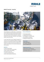
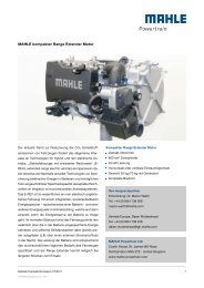
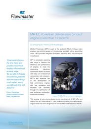

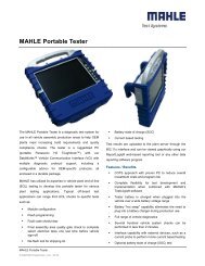
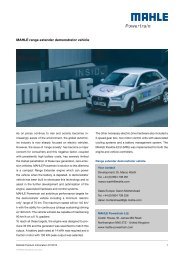
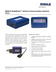

![[PDF] Dust collector SFR-08 - mahle.com](https://img.yumpu.com/37394977/1/184x260/pdf-dust-collector-sfr-08-mahlecom.jpg?quality=85)