Underground Construction for a Combined Sewer Overflow System ...
Underground Construction for a Combined Sewer Overflow System ...
Underground Construction for a Combined Sewer Overflow System ...

Create successful ePaper yourself
Turn your PDF publications into a flip-book with our unique Google optimized e-Paper software.
<strong>Underground</strong> <strong>Construction</strong> <strong>for</strong> a <strong>Combined</strong> <strong>Sewer</strong> <strong>Overflow</strong> <strong>System</strong> in<br />
Providence, Rhode Island<br />
John L. Kaplin<br />
Gilbane<br />
Jeffrey P. Peterson<br />
Jacobs Associates<br />
Philip H. Albert<br />
Narragansett Bay Commission<br />
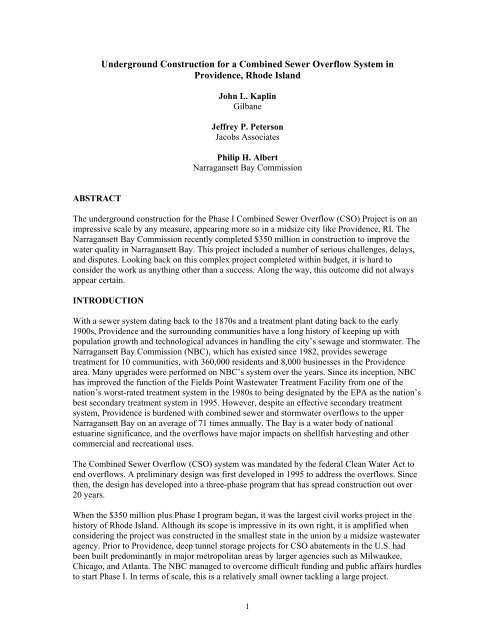
ABSTRACT<br />
The underground construction <strong>for</strong> the Phase I <strong>Combined</strong> <strong>Sewer</strong> <strong>Overflow</strong> (CSO) Project is on an<br />
impressive scale by any measure, appearing more so in a midsize city like Providence, RI. The<br />
Narragansett Bay Commission recently completed $350 million in construction to improve the<br />
water quality in Narragansett Bay. This project included a number of serious challenges, delays,<br />
and disputes. Looking back on this complex project completed within budget, it is hard to<br />
consider the work as anything other than a success. Along the way, this outcome did not always<br />
appear certain.<br />
INTRODUCTION<br />
With a sewer system dating back to the 1870s and a treatment plant dating back to the early<br />
1900s, Providence and the surrounding communities have a long history of keeping up with<br />
population growth and technological advances in handling the city’s sewage and stormwater. The<br />
Narragansett Bay Commission (NBC), which has existed since 1982, provides sewerage<br />
treatment <strong>for</strong> 10 communities, with 360,000 residents and 8,000 businesses in the Providence<br />
area. Many upgrades were per<strong>for</strong>med on NBC’s system over the years. Since its inception, NBC<br />
has improved the function of the Fields Point Wastewater Treatment Facility from one of the<br />
nation’s worst-rated treatment system in the 1980s to being designated by the EPA as the nation’s<br />
best secondary treatment system in 1995. However, despite an effective secondary treatment<br />
system, Providence is burdened with combined sewer and stormwater overflows to the upper<br />
Narragansett Bay on an average of 71 times annually. The Bay is a water body of national<br />
estuarine significance, and the overflows have major impacts on shellfish harvesting and other<br />
commercial and recreational uses.<br />
The <strong>Combined</strong> <strong>Sewer</strong> <strong>Overflow</strong> (CSO) system was mandated by the federal Clean Water Act to<br />
end overflows. A preliminary design was first developed in 1995 to address the overflows. Since<br />
then, the design has developed into a three-phase program that has spread construction out over<br />
20 years.<br />
When the $350 million plus Phase I program began, it was the largest civil works project in the<br />
history of Rhode Island. Although its scope is impressive in its own right, it is amplified when<br />
considering the project was constructed in the smallest state in the union by a midsize wastewater<br />
agency. Prior to Providence, deep tunnel storage projects <strong>for</strong> CSO abatements in the U.S. had<br />
been built predominantly in major metropolitan areas by larger agencies such as Milwaukee,<br />
Chicago, and Atlanta. The NBC managed to overcome difficult funding and public affairs hurdles<br />
to start Phase I. In terms of scale, this is a relatively small owner tackling a large project.<br />
1
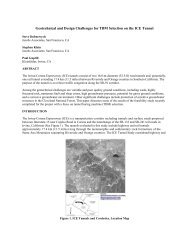
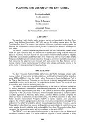
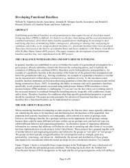
Figure 1 shows the Phase I layout. Starting in 2001, nine construction contracts were issued to<br />
build the Phase I CSO system. The subject of this paper is one of these contracts, Contract 6,<br />
which was the largest and covered the underground works. It was completed between 2002 and<br />
2007 by Shank/Balfour Beatty (S/BB) with a final contract value of $173 million, 6% above the<br />
original bid. The scope of the contract is summarized in Table 1.<br />
FIGURE 1. Location Plan.<br />
Work<br />
Element<br />
Shafts<br />
(six total)<br />
Main Spine<br />
Tunnel<br />
(MST)<br />
Adits<br />
(seven total)<br />
Pump<br />
Cavern<br />
TABLE 1. Contract 6 scope of work<br />
Description<br />
• S-1: main work shaft servicing MST; screening shaft <strong>for</strong> permanent works.<br />
• Utility and Access: servicing the pump cavern.<br />
• Foundry: north terminus of MST; vent shaft <strong>for</strong> permanent works.<br />
• 067: drop and vent shafts <strong>for</strong> a CSO connection (six other locations constructed<br />
under other contracts; not in scope of this paper).<br />
4,963 m (16,284 ft) long, 7.9 m (26 ft) diameter, 70 m (230 ft) deep. This is the main<br />
CSO storage tunnel, which can hold 235 million liters (62 million gallons).<br />
2.7 to 4.8 m (8.75 to 15.75 ft) diameter deaeration chambers; 2.4 m (8 ft) diameter<br />
adits. Adits inclusive of chambers total 1,237 m (4,057 ft) in length. Convey CSO<br />
flows from drop shafts to MST.<br />
A 189 ML/day (50 MGD) Field’s Point Pump Station housed in a 92 m (300 ft) deep<br />
rock cavern with dimensions of 35.7 m × 18.6 m × 20.7 m (117 ft × 61 ft × 68 ft).<br />
S/BB constructed the cavern, floor, and roof; all other fit-out work was per<strong>for</strong>med in<br />
subsequent contract. The Contract 6 pump cavern work is not covered in this paper<br />
(see Hughes et al. 2008).<br />
2
Other Phase I contracts outside the bounds of this paper include six construction packages that tie<br />
the existing CSO system to the tunnel. Each of these packages consists of diversion structures,<br />
connecting conduits, gate and screening structures, and drop and vent shafts drilled down from<br />
the surface. The construction of these shafts is discussed in Castro et al. (2007). There also is a<br />
$54 million contract in the final stages of completion to fit-out an underground pump cavern with<br />
a 189 ML/day pump station, construct associated support buildings, and complete the mechanical,<br />
electrical, and instrumentation work. As of this writing, all of this work is sufficiently completed<br />
such that the bulk of Providence’s storm overflows within the Phase I area is now collected in a<br />
tunnel rather than polluting the bay. Effluent is pumped from the tunnel after storms to the<br />
existing Fields Point Treatment Plant at the south end of Providence.<br />
Three bids were received <strong>for</strong> Contract 6 on September 25, 2001, ranging from $163.5 million to<br />
$227.4 million. As low bidder, S/BB was awarded the contract in December 2001. S/BB<br />
mobilized to the site in early 2002.<br />
SHAFTS<br />
First, three shafts were sunk at the S-1 site at the southern terminus of the project, near the Field’s<br />
Point Treatment Plant at the Port of Providence. The S-1 was sunk first, starting in 2002,<br />
followed by the Utility and Access shafts. <strong>Construction</strong> on the Foundry shaft at the northern end<br />
of the Main Spine Tunnel (MST) started later, in 2003, as it would not be needed until the MST<br />
hole-through. The 067 drop and vent shafts were frozen and raise-bored near the tail end of<br />
Contract 6. Table 2 summarizes pertinent facts about these six shafts.<br />
Excavation<br />
diameter<br />
Finish<br />
diameter<br />
Depth to<br />
water table<br />
Depth to top<br />
of rock<br />
Depth of shaft<br />
Soil support<br />
method<br />
Initial and<br />
final shaft<br />
liners<br />
S-1<br />
Shaft<br />
m (ft)<br />
Soil: 15.2 (50)<br />
circular<br />
Rock: 10.4 (34)<br />
square<br />
7.9<br />
(26)<br />
4.6<br />
(15)<br />
50<br />
(165)<br />
89<br />
(292)<br />
TABLE 2. Shaft excavation data<br />
Utility Access Foundry<br />
Shaft Shaft Shaft<br />
m (ft) m (ft) m (ft)<br />
11<br />
(36)<br />
9.8<br />
(32)<br />
6.4<br />
(21)<br />
48<br />
(157)<br />
74<br />
(242)<br />
4.3<br />
(14)<br />
3.4<br />
(11)<br />
6.4<br />
(21)<br />
53<br />
(174)<br />
74<br />
(242)<br />
11<br />
(36)<br />
7.9<br />
(26)<br />
7<br />
(23)<br />
46<br />
(152)<br />
78<br />
(257)<br />
Ground freezing<br />
Cast-in-place concrete, slip-lining method<br />
OF-067<br />
Drop Shaft<br />
m (ft)<br />
3.7<br />
(12)<br />
2.7<br />
(9)<br />
4<br />
(13)<br />
50<br />
(164)<br />
71<br />
(233)<br />
OF-067<br />
Vent Shaft<br />
m (ft)<br />
1.8<br />
(6)<br />
1.2<br />
(3.9)<br />
4<br />
(13)<br />
50<br />
(164)<br />
71<br />
(233)<br />
The S-1 is the main work shaft from which the MST was excavated. As noted in Table 2, the<br />
depth to bedrock is quite deep at 50 m (165 ft). The freezewall constructed to provide soil support<br />
<strong>for</strong> this shaft encountered a substantial delay, which impacted the critical path schedule of the<br />
project and the overall Phase I program. It was originally estimated that the freezewall would<br />
close in 38 days from the start of the freeze, and by 50 days the freezewall thickness would be<br />
sufficient <strong>for</strong> excavation to start. The actual duration <strong>for</strong> closure was 122 days, and excavation<br />
started at 138 days. Further time was lost during the shaft excavation due to the increased ice<br />
growth inward during the initial freeze delay. This additional frozen ground had to be chipped by<br />
3
impact hammer, prolonging the excavation far beyond the time it would have taken had the bulk<br />
of the core remained unfrozen as planned. These events led to considerable ef<strong>for</strong>ts to determine<br />
cause and mitigate delays. The contractors worked aggressively to resolve the freezing problems<br />
with a variety of techniques, including additional freeze pipes, instrumentation, grouting, and<br />
pump tests.<br />
After the freezewall closed and soil excavation was completed, the contractor and freezewall<br />
subcontractor submitted a claim that contended that three differing site conditions (DSCs) had<br />
interacted to cumulatively delay the freeze. They claimed that “free-phase” gasoline<br />
contamination delayed the freeze near the top of the shaft and was remedied by the installation of<br />
shallow freeze pipes. This problem masked two deeper “windows” at 37 m and 47 m (120 ft and<br />
155 ft) depths caused by higher-than-anticipated permeability and groundwater flow up from<br />
bedrock through preconstruction grout holes that had been incompletely sealed by a previous<br />
NBC contractor.<br />
The owner’s team was not in complete agreement with the contractors’ explanations as to the<br />
causes <strong>for</strong> the freezewall problems. For example, no “free-phase” gasoline was ever discovered.<br />
When freezing was initiated, the shaft core had already been excavated nearly to the groundwater<br />
table, which was then exposed to hot summer temperatures that apparently overwhelmed the<br />
desired effect of the freeze pipes on groundwater temperature. Thus, warm water, not gasoline,<br />
was the most likely culprit of the shallow freeze problems, and this conclusion was supported by<br />
direct temperature measurements. As <strong>for</strong> the deep windows, the owner’s team concurred that<br />
there likely was leakage up from rock into the shaft core but found the flow could have come<br />
through bedrock fractures, a contractor’s own observation well, or grout holes as asserted. Soil<br />
permeability was found locally to be higher than anticipated; however, the gradient of the<br />
groundwater table was no steeper than described in the contract documents.<br />
There also was some debate about contract provisions, specifically whether the geotechnical<br />
in<strong>for</strong>mation included was sufficient to determine groundwater flow <strong>for</strong> the purposes of designing<br />
a freezewall, and whether the contractor needed to per<strong>for</strong>m investigations. This was never done,<br />
with the freezewall contractor arguing that the in<strong>for</strong>mation already included was adequate.<br />
Sorting out responsibility <strong>for</strong> delays on a freezewall claim with multiple problems is certainly not<br />
clear cut. In the end, agreement was reached as part of a global settlement. The lessons learned<br />
are that closer attention must be paid when determining whether groundwater flow at a site is an<br />
issue <strong>for</strong> ground freezing, who will conduct those investigations, and how it is accounted <strong>for</strong> in<br />
the design of the freezewall. Secondly, a shaft collar installed and soil excavated to near the<br />
groundwater table within the core also must be properly accounted <strong>for</strong> in the design of the<br />
freezewall, especially during summer months when elevated air temperatures may persist very<br />
close to the ground that is to be frozen. The causes and mitigation measures to resolve this<br />
problem are described in greater detail in Schmall et al. (2007), which presents the perspective of<br />
the ground-freezing contractor.<br />
The ground freezing at the other five shafts proceeded largely as planned. Cast-in-place (CIP)<br />
liners were used <strong>for</strong> longer-term soil support by means of the slip-lining method at all shafts,<br />
following which the ground-freeze systems were shut off. Excavation of rock in all the shafts was<br />
by drill and blast. The exception was the raiseboring of the 067 shafts. All shaft rock excavation<br />
proceeded without any noteworthy problems. However, there were some issues at the Foundry<br />
shaft that deserve mention, as briefly described below.<br />
4
During the drilling <strong>for</strong> Foundry shaft pregrouting from the surface and the subsequent installation<br />
of freeze pipes, heavy water losses and grout takes were observed in the upper 6–9 m (20–30 ft)<br />
of bedrock. No clear cause of permeable ground was detected in the core borings, so there<br />
naturally was cause <strong>for</strong> concern with shaft sinking through this ground. A decision was made to<br />
increase the length of freezewall pipes to a depth from surface of 56 m (185 ft), well into rock.<br />
When the shaft was excavated through this zone, the occurrence of 12–50 mm (0.5–2.0 in.) wide<br />
fractures filled with a clean, fine-to-medium sand of probable glacial origin were discovered at a<br />
depth of 6 m (20 ft) below the top of rock. Grout had penetrated some of the fractures, but<br />
incompletely. These fractures would have been heavy water makers had the ground not been<br />
frozen and subsequently sealed by the cast-in-place liner. Even then, chemical grouting through<br />
the CIP liner was required to cut off silt laden inflows that occurred through shrinkage cracks.<br />
These fractures also were observed to a lesser extent in the Utility shaft, where some remedial<br />
work was required. In fact, the authors are aware of other shafts in New England where this<br />
problem has been encountered. The common characteristics of these fractures are their<br />
occurrence in the upper 6 m (20 ft) of bedrock, an aperture of up to several inches, a filling of<br />
clean sand, and the potential to produce high inflows at depths below the water table. They often<br />
are undetected by the single boring typically used <strong>for</strong> shaft exploration and require grouting, time,<br />
and money so that shaft sinking can proceed. Perhaps these features are unique to shaft sinking at<br />
locations with a record of glacial activity.<br />
MAIN SPINE TUNNEL EXCAVATION<br />
It has been a practice of the M.L. Shank side of the S/BB team to design and build its own tunnel<br />
boring machines (TBMs), and the Contract 6 machine was a scaled-up version of their previous<br />
smaller TBMs. Other than the cutterhead, main shield, and tail shield being fabricated by Hitachi<br />
of Japan, the fabrication and assembly of the TBM and trailing gear were per<strong>for</strong>med by S/BB<br />
<strong>for</strong>ces.<br />
Under a value-engineering proposal, the tunnel liner was a composite consisting of 25.4 cm (10<br />
in.) thick precast segments and a cast-in-place liner 30.5 cm (12 in.) thick, placed after mining<br />
was completed. Installation of the precast segments was within the TBM shield. As the TBM<br />
advanced <strong>for</strong>ward and the four-piece, 1.2 m (4 ft) wide precast ring emerged from the tail shield,<br />
hydraulic jacks were engaged in a 0.6 m (2 ft) wide open key gap at the crown to expand the<br />
segments against the rock. Struts filling the key gap were installed thereafter to hold the segments<br />
in place.<br />
The cutterhead was 9.1 m (30 ft) in diameter and equipped with 65 43-cm (17-in.) diameter,<br />
back-loading cutters. The machine employed 20 jacks to propel and steer off precast segments,<br />
with a total available thrust of 28,024 kN (6,300,000 lb). The cutterhead was rotated at 3 to 5 rpm<br />
and was driven by 20 hydraulic motors rated at a total of 1,837 kW (2,465 hp). Power <strong>for</strong> the<br />
thrust, head rotation, conveyors, and segment erection was electric over hydraulic.<br />
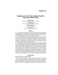
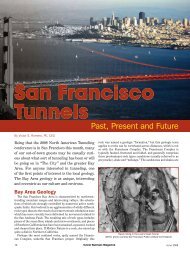
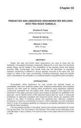
The TBM was launched from a starter tunnel at the S-1 shaft on March 8, 2004 (Figure 2). Within<br />
a month, production was in the 12.2 to 13.7 m/day (40 to 45 ft/day) range. Mining was per<strong>for</strong>med<br />
on one long shift, from 6:30 a.m. to 6 p.m., with maintenance per<strong>for</strong>med on the back shifts. The<br />
basic mining cycle consisted of mining through 1.2 m (4 ft) of rock in 25 to 40 min, separated by<br />
time to install segments and wait <strong>for</strong> trains. Haulage by rail was per<strong>for</strong>med by three locomotives<br />
hauling five muck cars and one segment car. Two rail switches were used—a fixed one at the S-1<br />
shaft and a second, <strong>for</strong>ward one that was periodically advanced toward the heading to improve<br />
rail transit. A muck car roll-over dump, a vertical conveyor in the shaft, and a radial stacking<br />
5
conveyor at the surface were used to move tunnel muck to a surface pile, where it was trucked off<br />
site <strong>for</strong> commercial uses. As with the TBM, most of this equipment was designed and fabricated<br />
by S/BB <strong>for</strong>ces.<br />
FIGURE 2. TBM in starter tunnel.<br />
The rock encountered in all the underground works was a weakly metamorphosed sequence of<br />
folded sedimentary rocks of the Rhode Island Formation that includes sandstone, shale, siltstone,<br />
graphitic shale, and conglomerate. With the exception of the graphitic shale, the rocks were stable<br />
with good stand-up time.<br />
A ground classification system <strong>for</strong> tunneling was included in the Geotechnical Baseline Report<br />
(GBR) and made part of the contract documents, as a two-pass lining system was permitted in the<br />
bid documents. The classification system was based on criteria that characterized the rock<br />
behavior and was intended <strong>for</strong> use in the selection of ground support. Type I ground required rock<br />
bolts and shotcrete; Type II ground called <strong>for</strong> steel sets, lagging, and shotcrete. S/BB’s precast<br />
segments installed immediately behind the TBM made the need to classify ground unnecessary.<br />
However, the classification system did become a source <strong>for</strong> a differing site condition (DSC) claim<br />
related to TBM penetration rate. S/BB anticipated that the TBM would penetrate weaker, broken<br />
ground faster than less-fractured, more-competent ground, relying upon the ground classification<br />
quantities provided in the GBR <strong>for</strong> its estimate. This was not an unreasonable approach, although<br />
certainly not the one intended by the authors of the report. Considerably more Type I ground was<br />
encountered in the MST than the 65% predicted by the GBR, and the actual TBM penetration rate<br />
was lower than bid. The claim was eventually settled as part of a global settlement.<br />
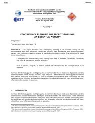
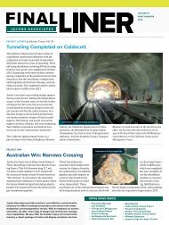
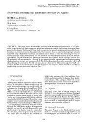
None of this should overshadow the overall per<strong>for</strong>mance of the TBM, which operated with a high<br />
degree of reliability and made steady progress. The TBM holed through at the Foundry shaft in<br />
early December 2005 (Figure 3). Production on the single long shift, five days a week, yielded<br />
274–427 m (900–1,400 ft) per month, with a daily production between 12.2 m and 18.3 m (40 ft<br />
and 60 ft) per mining day. Table 3 provides a summary of per<strong>for</strong>mance data <strong>for</strong> the TBM. One<br />
6
factor that affected monthly production was the number of days lost to mining to per<strong>for</strong>m preexcavation<br />
grouting, as discussed next.<br />
TABLE 3. TBM Production Data<br />
Description Quantity Unit<br />
Single-shift mining 10.5 h<br />
Average TBM penetration 2.1<br />
(6.8)<br />
m/h<br />
(ft/h)<br />
Average cycle time (mine 1.2 m [4 ft], erect segment ring;<br />
wait <strong>for</strong> next train at heading)<br />
54 min<br />
Mining 36 min<br />
Segment erect 11 min<br />
Wait <strong>for</strong> train at heading 7 min<br />
FIGURE 3. TBM cutterhead following hole-through at the Foundry shaft (photo by Sue Bednarz).<br />
PRE-EXCAVATION GROUTING<br />
It was anticipated that pre-excavation grouting would be required to maintain a total steady-state<br />
groundwater inflow from the MST, adits, and shafts below 12,490 Lpm (3,300 gpm). All inflow<br />
except that from the pump cavern was pumped from a dewatering station at the bottom of the S-1<br />
shaft to a settling pond and pretreatment system at the surface, then to the Field’s Point Treatment<br />
7
Plant <strong>for</strong> discharge. Contract specifications called <strong>for</strong> grouting if probe holes through the tunnel<br />
face, which had to provide continuous, overlapping coverage, produced greater than 190 Lpm (50<br />
gpm). Once triggered, grouting would be per<strong>for</strong>med using Type III or microfine cement grout.<br />
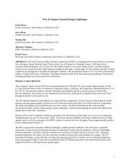
During the early stages of mining, inflow into the tunnel increased at a greater rate than<br />
anticipated, despite the use of the pre-excavation grouting program. By the time 25% of the MST<br />
had been mined, the inflow already had reached 4,540 Lpm (1,200 gpm), or 36% of the total<br />
anticipated inflow. For this reason, the grouting program was modified a number of times, and it<br />
is worth noting the more significant changes to the program based on conditions encountered. A<br />
summary is shown in Table 4. Figure 4 is a graphic of the inflow and the grout-event history.<br />
TABLE 4. Pre-excavation Grouting Program Summary<br />
Criteria Original Program Modified Program Discussion<br />
Grout trigger 190 Lpm<br />
(50 gpm)<br />
57 Lpm<br />
(15 gpm)<br />
Trigger was changed several times: first<br />
down to 26 Lpm (7 gpm), then up to 57<br />
Lpm (15 gpm), which was the predominant<br />
trigger during mining.<br />
Grout<br />
pressure<br />
3.5 MPa<br />
(500 psi)<br />
2.4 MPa<br />
(350 psi)<br />
At the higher pressures, grout takes were in<br />
the range of 142–170 m 3 (5,000–6,000 ft 3 )<br />
per event. It was judged that a considerable<br />
portion of the grout was pushed through<br />
fractures outside the tunnel envelope,<br />
perhaps due to hydrojacking. After the<br />
pressure was reduced, grout takes were<br />
lowered by a factor of two to four, with no<br />
apparent loss in effectiveness, as is visible<br />
in Figure 4 from Station 80+00 and<br />
beyond.<br />
Grout holes two four Based on inspection of the face, it was<br />
judged that two holes were insufficient <strong>for</strong><br />
a 9.1-m (30-ft) diameter face.<br />
Equipment<br />
Grout<br />
Cost<br />
Complete<br />
mobilization of all<br />
grouting equipment<br />
from surface to<br />
heading <strong>for</strong> each grout<br />
event, probing and<br />
grouting through one<br />
hole at a time.<br />
Microfine and<br />
Type III<br />
$5.8 million paid<br />
using unit price items<br />
Rolling gantry behind the TBM<br />
trailing gear was fabricated; included<br />
equipment to allow rapid<br />
mob/demob <strong>for</strong> grout events and<br />
ability to probe/grout two holes<br />
simultaneously. A second<br />
grouting/mixing plant was also<br />
fabricated to boost grouting capacity.<br />
Same. However, with probe flow of<br />
greater than 190 Lpm (50 gpm),<br />
Type III would be started with to<br />
reduce cost.<br />
$10 million using unit price items<br />
with quantities replenished through<br />
change order.<br />
No mining could be accomplished when<br />
pre-excavation grouting was per<strong>for</strong>med.<br />
Initially, mob/demob time resulted in two<br />
lost mining days per grout event. These<br />
equipment changes, which the owner paid<br />
<strong>for</strong> through a change order, reduced the lost<br />
mining days from two to one while<br />
increasing the number of holes that could<br />
be grouted at a time.<br />
This was done to reduce cost by initially<br />
filling heavy water-making fracture<br />
systems that took large quantities of grout<br />
at low pressure with the less-expensive<br />
Type III cement.<br />
All parties universally agreed that inflow<br />
had to be reduced by pre-excavation<br />
grouting to a point where it was<br />
manageable <strong>for</strong> mining and final CIP<br />
lining, and that cut-off grouting (attempting<br />
to grout off inflows after exposed in the<br />
mined opening) was not a reasonable<br />
approach. A total of 3,364 m 3 (4,400 yd 3 )<br />
of grout was pumped over 44 grouting<br />
events, or 59 working days.<br />
8
FIGURE 4. Water inflow and grout take per event in the Main Spine Tunnel.<br />
There was relatively little decay observed in the inflow rates over time in the MST. This<br />
assessment was based on direct measurement of sustained inflows. The overall effectiveness of<br />
pre-excavation grouting can there<strong>for</strong>e be analyzed in rough terms by comparing probe inflow to<br />
tunnel inflow in grouted versus ungrouted portions of the tunnel. The results are shown in Table<br />
5.<br />
TABLE 5. Pre-excavation grouting per<strong>for</strong>mance summary.<br />
Grouted versus ungrouted intervals of the Main Spine Tunnel<br />
Interval<br />
length,<br />
m (ft)<br />
Increased<br />
inflow in<br />
tunnel,<br />
Lpm (gpm)<br />
Cumulative<br />
probe inflow<br />
<strong>for</strong> interval,<br />
Lpm (gpm)<br />
Ratio of<br />
increased<br />
tunnel inflow/<br />
probe inflow<br />
Grouted<br />
intervals<br />
2,425<br />
(7,957)<br />
4,546<br />
(1,201)<br />
12,343<br />
(3,261)<br />
0.37<br />
Ungrouted<br />
intervals<br />
2,275<br />
(7,465)<br />
5,435<br />
(1,436)<br />
1,154<br />
(305)<br />
4.71<br />
It is critical to understand the purpose of a grouting and water handling program in a rock tunnel.<br />
In this case, the intention was to keep inflow at a level manageable <strong>for</strong> tunneling equipment<br />
operation and successful placement of the CIP liner without washout. Following placement of the<br />
liner, subsequent contact grouting and a final round of chemical grouting at a few select locations,<br />
9
the long-term, steady-state inflow from the MST, all adits, and connecting shafts was<br />
approximately 1,140 Lpm (300 gpm).<br />
ADIT CONSTRUCTION<br />
Seven adits were excavated off the MST to connect the tunnel to the drop and vent shafts<br />
previously installed by other NBC contractors. To mitigate the schedule loss of a year’s time that<br />
occurred prior to the start of MST mining, all adits were excavated and lined concurrently with<br />
the excavation of the MST. The exceptions were the 067 and WRI adits, which were driven from<br />
the base of the S-1 and Foundry shafts, respectively. Elevated decks were constructed in the MST<br />
at each of the adit portals to service the adit excavation and concrete lining. This allowed access<br />
to the adits, which intersected the MST at the spring line while allowing MST train traffic to pass<br />
unimpeded beneath the deck (Figure 5).<br />
FIGURE 5. Elevated deck <strong>for</strong> construction of the adit from the Main Spine Tunnel.<br />
Excavation was by drill and blast and proceeded on a 24-hour basis. Most of the blasting was<br />
per<strong>for</strong>med on the second and third shifts so as to avoid interference with the daytime MST mining<br />
operation. Considerable outreach helped project neighbors understand the program and allayed<br />
common fears that come with blasting. Convincing authorities to permit 24-hour blasting was<br />
also simplified because few businesses above the adits operated at night and there were few<br />
residences.<br />
One of the adit alignments is beneath the main power plant in the city, causing concern with the<br />
local hospital, which had previously experienced power outages unrelated to construction.<br />
Through meetings and test blasts, these concerns also were addressed, and adit excavation<br />
proceeded as planned.<br />
Ground support consisted of swellex bolts and shotcrete in competent rock (Type I ground). Steel<br />
sets, lagging, and shotcrete were used where weak graphitic shale was encountered (Type II<br />
ground). Probing ahead of the excavation face was per<strong>for</strong>med, yet pre-excavation grouting was<br />
triggered rarely and water inflow was generally not a problem in the adits. Table 6 provides a<br />
summary of pertinent adit/chamber data.<br />
10
TABLE 6. Adit/Deaeration Chamber Summary<br />
Adit<br />
Chamber<br />
Adit<br />
067<br />
004/<br />
061<br />
MRI<br />
006/<br />
007<br />
009/<br />
010<br />
032<br />
WRI<br />
Adit<br />
length<br />
m (ft)<br />
3.0<br />
(9.7)<br />
1.5<br />
(5)<br />
521<br />
(1,710)<br />
96<br />
(314)<br />
40<br />
(132)<br />
226<br />
(740)<br />
189<br />
(619)<br />
Chamber<br />
length<br />
m (ft)<br />
36<br />
(117.5)<br />
20<br />
(65.5)<br />
20<br />
(65.5)<br />
20<br />
(65.5)<br />
36<br />
(117.5)<br />
20<br />
(65.5)<br />
20<br />
(65.5)<br />
Total<br />
length<br />
m (ft)<br />
39<br />
(127.2)<br />
22<br />
(70.5)<br />
541<br />
(1,776)<br />
116<br />
(380)<br />
76<br />
(250)<br />
246<br />
(806)<br />
209<br />
(685)<br />
Adit<br />
Excavated<br />
Diameter<br />
m (ft)<br />
3.4<br />
(11.3)<br />
3.4<br />
(11.3)<br />
3.4<br />
(11.3)<br />
3.4<br />
(11.3)<br />
3.4<br />
(11.3)<br />
3.4<br />
(11.3)<br />
3.4<br />
(11.3)<br />
Finished<br />
Diameter<br />
m (ft)<br />
2.4<br />
(8)<br />
1.4<br />
(4.5)<br />
2.4<br />
(8)<br />
2.4<br />
(8)<br />
2.4<br />
(8)<br />
2.4<br />
(8)<br />
2.4<br />
(8)<br />
Chamber<br />
Excavated<br />
Diameter<br />
m (ft)<br />
5.8<br />
(19)<br />
3.7<br />
(12)<br />
3.7<br />
(12)<br />
3.7<br />
(12)<br />
5.8<br />
(19)<br />
3.7<br />
(12)<br />
4.3<br />
(14)<br />
Chamber<br />
Finished<br />
Diameter<br />
m (ft)<br />
4.8<br />
Ratio<br />
Type I/II<br />
Ground<br />
%<br />
Shifts to<br />
excavate<br />
(15.75) 100/0 69<br />
2.7<br />
(8.75) 100/0 28<br />
2.7<br />
(8.75) 86/14 386<br />
2.7<br />
(8.75) 100/0 81<br />
4.8<br />
(15.75) 100/0 83<br />
2.7<br />
(8.75) 100/0 152<br />
3.2<br />
(10.5) 33/67 143<br />
The deaeration chamber connections to the drop and vent shafts installed under other NBC<br />
contracts proceeded as planned with one exception. A failure of the shaft liner was experienced<br />
just above the intersection with the chamber at one adit where Embedded Cylinder Pipe (ECP)<br />
had been used <strong>for</strong> a shaft liner. In just a few hours, the mortar lining spalled off the bottom 6 m<br />
(20 ft) of the shaft in dramatic fashion, and the thin steel lining ballooned inwards under the<br />
groundwater pressure, pinching the shaft diameter to a few feet. It was apparent that water had<br />
leaked in between the inner layers of the pipe, causing it to burst. The failed pipe section was<br />
removed and repaired with mesh and shotcrete. In hindsight, a steel transition section <strong>for</strong> the<br />
bottom 3 m (10 ft) of each shaft where cylinder pipe was selected would have been far more<br />
robust and able to withstand the rigors of the chamber excavation and shaft installation. For three<br />
other locations that also had ECP pipes used <strong>for</strong> shaft liners, procedures were revised and all were<br />
completed without problems.<br />
Concrete lining and contact grouting of the adits and deaeration chambers was accomplished by<br />
pumping from a surface pump fed by ready-mix trucks through slicklines run down the drop<br />
shafts.<br />
MAIN SPINE TUNNEL—FINAL LINING<br />
The final cast-in-place MST liner was constructed from the Foundry shaft to the S-1 shaft by<br />
pumping concrete from the surface at four locations. A fleet of ready-mix trucks delivered 27.6<br />
MPa (4,000 psi) concrete with 10 mm (3/8 in.) stone from a batch plant constructed and operated<br />
by S/BB at the S-1 site. The maximum pumping distance was 1,006 m (3,300 ft) from the pump<br />
to the <strong>for</strong>ms. Additives included new generation full-range and high-range water reducing<br />
admixtures, retarder, fly ash, and an air-entraining admixture. A total of 44,340 m 3 (58,000 yd 3 ) of<br />
cast-in-place concrete was placed in the MST <strong>for</strong> the final lining.<br />
Once beyond the initial learning curve, 50 m/day (165 ft/day) placements were achieved. This<br />
required a sustained delivery of 443 m 3 (580 yd 3 ) over eight hours. A bulkhead was constructed at<br />
the downstream end (Figure 6) <strong>for</strong> each day’s pour, and concrete was typically filled to a height<br />
11
of approximately 80% full or higher, leaving a sloping construction joint. Within the <strong>for</strong>ms, a<br />
slickline at the crown was dragged along hanging rollers as the pour progressed.<br />
FIGURE 6. Gantry <strong>for</strong> bulkhead construction at downstream end of Main Spine Tunnel <strong>for</strong>ms.<br />
When the liner was nearly complete, displacement was observed to have occurred along this<br />
construction joint at about half of the 100 bulkhead locations. In the most severe case, a concrete<br />
block approximately 0.6 m × 1.2 m (2 ft × 4 ft) fell to the invert. An investigation revealed that<br />
concrete in the crown area was displacing away from the precast segments along the sloping<br />
joints, possibly as a result of increasing pressure from the recovering groundwater table. A repair<br />
plan was developed and implemented to remove the displaced concrete, install dowels, and<br />
backfill with shotcrete. Pressure relief holes were added to the problem areas. Repairs were<br />
completed without impact to the project schedule, and costs to per<strong>for</strong>m this work were split<br />
between the NBC and S/BB. An inspection per<strong>for</strong>med a year after the work was completed<br />
revealed that the repairs were successful. In the future, the authors suggest that the use of sloping<br />
cold joints in large diameter cast-in-place liners should be avoided and full bulkhead pours<br />
stipulated as a requirement.<br />
CLOSING<br />
A year was lost on the schedule prior to the start of MST mining. Of this, six months is accounted<br />
<strong>for</strong> on the S-1 shaft freeze and excavation. A concurrent and continuing delay associated with<br />
TBM delivery, fabrication, and setup in the starter tunnel resulted in an additional four-month<br />
slippage. S/BB developed a recovery plan to mine and line six of the seven adits concurrently<br />
with MST mining. This plan was successful in preventing further schedule loss and was well<br />
managed by S/BB. Figure 7 depicts a comparison of the planned and actual project schedules.<br />
12
S-1 Shaft - excavate<br />
2002 2003 2004 2005<br />
2006 2007<br />
J F M A M J J A S O N D J F M A M J J A S O N D J F M A M J J A S O N D J F M A M J J A S O N D J F M A M J J A S O N D J F M A M<br />
TBM Fabrication/Delivery/Assembly at surface<br />
Starter Tunnel/TBM Set-up underground<br />
Main Spine Tunnel - Mining<br />
Foundry Shaft/WRI Adit - excavate/line<br />
Adits - 004/061 - MRI - 006/007 - 009 - 032<br />
Utility/Access Shaft - excavate/line<br />
Pump Cavern<br />
Main Spine Tunnel - Lining/Contact Grouting<br />
067 Adit - excavate/line<br />
067 Shafts - excavate/line<br />
S-1 Shaft Lining/final clean-up<br />
as-planned<br />
March, 2006 completion<br />
as-built<br />
March 2007 completion<br />
FIGURE 7. Comparison of planned and actual schedules.<br />
Contract 6 was completed within budget and at a final contract price within 6% of the original bid<br />
price. Although some delays also occurred on the shaft/surface contracts, the overall Phase I<br />
program also was completed within budget and within 7% of the total original bid price.<br />
Prior to the Phase I CSO, the last major tunneling project completed in Providence was over 50<br />
years ago, and it was a relatively short bus tunnel. Phase I remained largely out of the local press,<br />
allowing the project to achieve its objectives without negative reviews. Multiple tunneling<br />
technologies were used to improve the environment, in this case Narragansett Bay. This project is<br />
an example of how a public agency in a midsize city like Providence, without significant<br />
tunneling experience, can tackle a large and complex underground project <strong>for</strong> the benefit of its<br />
citizens and do it within budget. Tackling problems early and head on is one of the keys to<br />
success, particularly with large projects.<br />
REFERENCES<br />
Castro, R., Vincent, F., Hughes, G., and Albert, P. 2007. Drop shafts <strong>for</strong> Narragansett Bay<br />
Commission CSO Abatement Program. In Proceedings of the Rapid Excavation and Tunneling<br />
Conference, ed. M.T. Taylor and J.W. Townsend. Society <strong>for</strong> Mining, Metallurgy, and<br />
Exploration.<br />
Hughes, G., Kaplin, J., Halim, I, Albert, P. 2008. Design and construction of the Fields Point<br />
Tunnel Pump Station <strong>for</strong> the Narragansett Bay Commission CSO Abatement Program,<br />
Providence, Rhode Island. In Proceedings of the North American Tunneling Conference, ed. M.T.<br />
Taylor and J.W. Townsend. Society <strong>for</strong> Mining, Metallurgy, and Exploration.<br />
Schmall, P., Corwin, B., Spiteri, P. 2007. Ground freezing under the most adverse conditions:<br />
Moving groundwater. In Proceedings of the Rapid Excavation and Tunneling Conference, ed.<br />
M.F. Roach, M.R. Kritzer, D. Ofiara, and B.F. Townsend. Society <strong>for</strong> Mining, Metallurgy, and<br />
Exploration.<br />
13