

Ripple tank - Serrata Science Equipment
Ripple tank - Serrata Science Equipment
Ripple tank - Serrata Science Equipment

You also want an ePaper? Increase the reach of your titles
YUMPU automatically turns print PDFs into web optimized ePapers that Google loves.
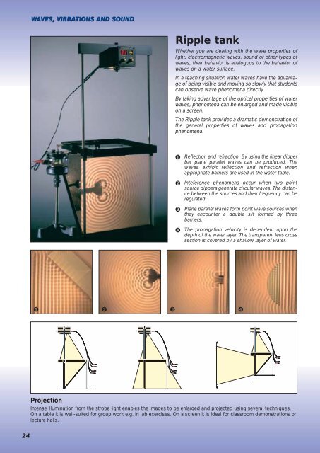
WAVES, VIBRATIONS AND SOUND<br />
<strong>Ripple</strong> <strong>tank</strong><br />
Whether you are dealing with the wave properties of<br />
light, electromagnetic waves, sound or other types of<br />
waves, their behavior is analogous to the behavior of<br />
waves on a water surface.<br />
In a teaching situation water waves have the advantage<br />
of being visible and moving so slowly that students<br />
can observe wave phenomena directly.<br />
By taking advantage of the optical properties of water<br />
waves, phenomena can be enlarged and made visible<br />
on a screen.<br />
The <strong>Ripple</strong> <strong>tank</strong> provides a dramatic demonstration of<br />
the general properties of waves and propagation<br />
phenomena.<br />
➊ Reflection and refraction. By using the linear dipper<br />
bar plane parallel waves can be produced. The<br />
waves exhibit reflection and refraction when<br />
appropriate barriers are used in the water table.<br />
➋ Inteference phenomena occur when two point<br />
source dippers generate circular waves. The distance<br />
between the sources and their frequency can be<br />
regulated.<br />
➌ Plane parallel waves form point wave sources when<br />
they encounter a double slit formed by three<br />
barriers.<br />
➍ The propagation velocity is dependent upon the<br />
depth of the water layer. The transparent lens cross<br />
section is covered by a shallow layer of water.<br />
➊ ➋ ➌ ➍<br />
Projection<br />
Intense illumination from the strobe light enables the images to be enlarged and projected using several techniques.<br />
On a table it is well-suited for group work e.g. in lab exercises. On a screen it is ideal for classroom demonstrations or<br />
lecture halls.<br />
24
WAVES, VIBRATIONS AND SOUND<br />
F<br />
D<br />
E<br />
J<br />
G<br />
B<br />
K<br />
A<br />
A<br />
B<br />
C<br />
D<br />
E<br />
F<br />
G<br />
H<br />
I<br />
J<br />
K<br />
C<br />
H<br />
Vibrator<br />
Wavegenerator in phase with strobelight.<br />
Support with height adjustment<br />
The generator assembly can be adjusted so that the dippers<br />
just touch the water.<br />
<strong>Ripple</strong> <strong>tank</strong><br />
Manufactured of lacquered aluminum.<br />
Wave dampers<br />
Impede the reflection of incident waves.<br />
Glass bottom surface<br />
Easy to clean and scratch resistant.<br />
Stroboscope<br />
The ventilated, point source halogen lamp provides a sharp<br />
image with high luminance. Frequency regulation for stopmotion<br />
or slow motion of the waves. Regulates power to the<br />
vibrator and permits direct frequency readout.<br />
Projection mirror<br />
Scratch resistant and easy to clean with protective backing<br />
plate.<br />
Projection screen<br />
A specially produced projection screen ensures optimum<br />
sharpness.<br />
Footers with adjustment screws<br />
The <strong>Ripple</strong> <strong>tank</strong> is supported by three legs to ensure a stable<br />
setup and to permit exact regulation of water depth.<br />
Power supply<br />
The only supply voltage needed is 12 VDC (5 A).<br />
Wave dippers<br />
The standard set includes various dippers and lens profiles.<br />
I<br />
The vibrator is overloadprotected. The moving parts are controlled<br />
by means of a double membrane. Height regulation of<br />
the dippers is continuous using finger screws. The horizontal<br />
position can also be adjusted.<br />
The vibrator assembly can also be used to generate waves<br />
on a string, in connection with resonance phenomena on flat<br />
plates and for the demonstration of the states of matter.<br />
25
WAVES, VIBRATIONS AND SOUND<br />
1<br />
1<br />
4<br />
5<br />
8<br />
9<br />
2<br />
6<br />
13<br />
3<br />
7<br />
10<br />
12<br />
11<br />
20<br />
18<br />
19 14<br />
The complete wave<br />
table set consists of:<br />
1: Stroboscope<br />
2: Stroboscope disk<br />
3: Stroboscope holder<br />
assembly<br />
4: Stroboscope rods<br />
5: Electromechanical<br />
vibrator<br />
6: Seesaw arm<br />
7: Seesaw arm support<br />
8: Support tap<br />
9: Height regulation<br />
10: Accessory set<br />
11: Connection cord<br />
12: Remote control<br />
13: Bottle with wetting agent<br />
14: Plane mirror<br />
15: Projection screen<br />
16: Adjustable legs (3)<br />
17: Horizontal support<br />
- front legs<br />
18: Angle brackets for<br />
projection screen (2)<br />
19: <strong>Ripple</strong> <strong>tank</strong><br />
20: Glass objects (3)<br />
The ripple <strong>tank</strong> set is supplied complete in a fiber box<br />
segmented for storing the components and with complete<br />
user instructions.<br />
16<br />
17<br />
15<br />
Additional<br />
<strong>Equipment</strong> Needed<br />
The only accessories<br />
are a low-voltage<br />
12 V DC, 5 A power<br />
supply (3610.50) and a<br />
tripod for the<br />
adjustable support<br />
(0006.00).<br />
2210.50 <strong>Ripple</strong> Tank, Complete<br />
Electromechanical<br />
Vibrator<br />
The vibrator generates mechanical vibrations when<br />
used with a signal generator as e.g. catalog no.<br />
2500.00 or 2501.50. The input signal is supplied to a<br />
coil which is mounted in a magnetic field from a cylindrical<br />
magnet. The unit is fuse-protected.<br />
It is supplied with a lock which protects moving parts<br />
while changing accessories. It is supplied with mounting<br />
hardware, a string holder and extra fuses.<br />
Max. input: 6 V/1A.<br />
Dimensions: 100 mm diameter x 120 mm.<br />
Mass: 1.26 kg<br />
2185.00<br />
2185.00 Electromechanical Vibrator<br />
26
WAVES, VIBRATIONS AND SOUND<br />
Vibrator accessories:<br />
Piano Wire Ring<br />
For use with 2185.00 for demonstrating the relationship<br />
between frequency and the number of vibrational nodes.<br />
Ring diameter: 290 mm.<br />
2185.10 Piano Wire Ring<br />
2155.50<br />
2185.10<br />
Chladni Plates<br />
For use with 2185.00. A thin layer of fine sand is spread<br />
over the plate, and resonance patterns ("Chladni" figures)<br />
can be observed at certain frequencies. The plate resonances<br />
are audible.<br />
2185.20 Resonance Plate, Square<br />
2185.25 Resonance Plate, Circular<br />
2185.20<br />
Flat Springs for Resonance Experiments<br />
Various lengths. For use with the 2185.00. Fundamental<br />
frequencies at 11, 15, 21, 36 and 50 Hz can be readily<br />
observed. Interesting standing waves can be seen up to<br />
300 Hz and heard up to 900 Hz.<br />
2185.30 Flat Springs for Resonance Experiments<br />
Rubber String<br />
2 meters. For use with 2185.00 for demonstrating<br />
standing waves.<br />
2185.40 Rubber String<br />
2185.25<br />
2185.30<br />
2185.40<br />
27
WAVES, VIBRATIONS AND SOUND<br />
Gas Model with Piston<br />
For use with the 2185.00. Ball bearings in motion represent gas molecules which lift a plastic piston due to repeated<br />
collisions. The model is supplied with the piston, ball bearings and a support for placing the apparatus on an overhead<br />
projector.<br />
2185.50<br />
2185.50 Gas Model with Piston<br />
Solids. Gas in piston. The gaseous state. Brownian motion. Boiling liquid.<br />
Lissajous' apparatus<br />
This apparatus is actually a simple oscilloscope. A<br />
mirror is mounted on a moveable steel ball held by<br />
two strips of spring steel. The two steel strips are<br />
spring loaded at one end and each controlled by a<br />
2185.00 vibrator at the other. By regulating the oscillations<br />
with the two vibrators, one can control the<br />
motion of the mirror in two mutually perpendicular<br />
directions and thus control the laser beam reflected<br />
by the mirror. The light source can be a gas laser, a<br />
diode laser or similar light source. The vibrators, signal<br />
generators and light source are not included.<br />
2185.60 Lissajous' apparatus<br />
2185.60<br />
ADDITIONAL EQUIPMENT NEEDED<br />
2 ea. Electromagnetic vibrators (2285.00)<br />
2 ea. Signal generators (e.g. 2500.50)<br />
1 ea. Laser (2885.00)<br />
28
WAVES, VIBRATIONS AND SOUND<br />
HE-NE LASER FOR INTERFERENCE EXPERIMENTS<br />
HE-NE LASER 1 MW<br />
Safety filter and shutter.<br />
2885.00<br />
Standard thread for<br />
objectives.<br />
He-Ne Laser, Modulated, 1 mW<br />
Laser like the 2885.00 but with the option of modulating<br />
the light beam. The laser is provided with a BNC-connector<br />
for connection to a signal generator, CD-player or similar<br />
signal source. The light beam intensity will then vary<br />
with the applied signal. Well suited for demonstration of<br />
optical communication using photodetector no. 4895.50.<br />
Maximum modulation frequency: 1 MHz.<br />
2885.20 He-Ne Laser, Modulated, 1 mW<br />
The laser emits light with a wavelength of 632.8 nanometers.<br />
The emitted light is coherent, i.e. wave fronts propagate<br />
in the same phase over a large distance compared<br />
with ordinary light sources. The emitted light is highly<br />
directional and the beam diameter at the laser is about<br />
0.5 mm increasing very gradually at increasing distances<br />
from the laser. The light emitted is not uniformly polarized<br />
but changes its polarization at random around the direction<br />
of propagation. Light from the laser is well-suited to<br />
demonstrations of optical interference. If a line grating is<br />
placed in the laser beam, the interference pattern will be<br />
clearly visible on a projection screen. The laser can be<br />
used for a wide range of applications in geometrical optics,<br />
holography, communication etc.<br />
2885.00 He-Ne Laser, 1 mW<br />
2885.10 He-Ne Laser, 2 mW<br />
Inteference Pattern Model<br />
for Overhead Projector<br />
The set consists of two transparent plastic plates with<br />
printed wave front patterns for point sources on each<br />
plate. If the plates are placed on top of one another and<br />
slightly displaced, an interference pattern will appear. The<br />
pattern can readily be projected onto a large viewing<br />
screen using an overhead projector.<br />
3235.00 Inteference Pattern Set<br />
3235.00<br />
4895.50<br />
Photodetector<br />
The photodetector is provided with a photo diode which<br />
can convert laser light intensity values to an electrical signal.<br />
The signal can be directed to the built in loudspeaker<br />
or be used for measurements via the analog and digital<br />
output connections. The photodetector can be used for<br />
demonstrating communication over a laser beam, fiber<br />
optic communication, plotting of interference patterns,<br />
etc. The maximum frequency is 1 MHz.<br />
4895.50 Photodetector<br />
29
WAVES, VIBRATIONS AND SOUND<br />
Wavelength of Light Apparatus<br />
The apparatus is designed to measure the wavelength of<br />
light by studying the interference pattern from a double<br />
slit. The device contains a built in 12 V auto lamp with a<br />
holder for color filters and a millimeter scale with phosphorescent<br />
moveable markers. The emitted light is<br />
viewed at a distance of about 3 meters through a double<br />
slit. The viewer then directs a co-worker to adjust the<br />
markers on the millimeter scale so that the distance<br />
between them corresponds to 10 interference maxima.<br />
Afterwards the distances can be measured and the<br />
wavelength of the light can be calculated. The equipment<br />
is well-suited to student lab exercises. Red and blue<br />
color filters and a double slit are provided.<br />
Power source required: 12 V AC/DC, 1.3 A.<br />
3240.00<br />
3240.00 Wavelength of Light Apparatus<br />
Function generator - DC amplifier<br />
Frequency counter<br />
Three functions are built into a single<br />
instrument with a digital<br />
display. The simple and<br />
well-organized operating<br />
panel makes the unit<br />
well-suited for demonstration<br />
experiments and for student<br />
experiments with vibrations,<br />
waves and much more.<br />
Compatible<br />
Function generator<br />
Sine, triangular and square<br />
wave signals with a broad,<br />
continuous frequency range are provided.<br />
Digital fine-tuning of frequency and amplitude are provided.<br />
The BNC output signal connection (0-20 Vpp) is<br />
short-circuit protected. Up to 10 W of output power are<br />
available via the amplifier. It is possible to demonstrate<br />
frequency modulation by connecting an external signal.<br />
DC amplifier<br />
The short-circuit proof 10 W power amplifier has a frequency<br />
range from 0 - 50 kHz.<br />
The amplifier can be used to amplify signals from the<br />
function generator or from external sources.<br />
The input of external signals is via BNC connectors with<br />
an impedance of 10 kΩ, and the output signal is accessible<br />
via safety-type banana jack connectors.<br />
Frequency counter<br />
The meter is fully automatic, and it can measure external<br />
frequencies from 0.1 Hz to 150 kHz.<br />
Serial computer interface<br />
The instrument is supplied with a RS-232 serial computer<br />
interface which makes it possible to perform remote<br />
control and readout of the instrument. This can be<br />
accomplished via the standard terminal program in<br />
Windows or by means of the program Datalyse.<br />
2501.50 Function Generator<br />
30
WAVES, VIBRATIONS AND SOUND<br />
Function Generator DC Amplifier<br />
The function generator has a broad frequency range and<br />
a built-in power amplifier. The frequency range is divided<br />
into eight regions which can be adjusted and read off the<br />
adjustment knob scale. It is possible to perform frequency<br />
modulation (FM) and external control of frequency.<br />
The function generator is well-suited for use by both students<br />
and teachers.<br />
2500.50<br />
2500.50 Function generator<br />
● Sine, triangular and square wave signals.<br />
● Short-circuit protected inputs.<br />
● 10 W external/internal power amplifier.<br />
● TTL signal output.<br />
● FM modulation and frequency sweep within the<br />
performance range.<br />
Function generator - technical specifications:<br />
Instrument<br />
Function Generator<br />
DC Amplifier<br />
Function Generator<br />
DC Amplifier<br />
Frequency Counter<br />
Frequency region<br />
0,1 Hz – 1 Hz<br />
1 Hz – 10 Hz<br />
10 Hz – 100 Hz<br />
100 Hz – 1000 Hz<br />
1 kHz – 10 kHz<br />
10 kHz – 100 kHz<br />
100 kHz – 1000 kHz<br />
1 MHz – 10 MHz<br />
0,1 Hz – 100 kHz in one range<br />
Signal type<br />
Sine, triangular, square wave<br />
Sine, triangular, square wave<br />
Signal output:<br />
Output voltage<br />
Output impedance<br />
Distortion<br />
±5.5 V pp and TTL 50 W < 1.3%<br />
0-20 V pp 600 W typically 0.5 %<br />
DC Amplifier<br />
Frequency Range<br />
Output Power<br />
Output Voltage<br />
Input Impedance<br />
DC - 50 kHz at -3 dB<br />
10 W RMS / 4 W<br />
± 10 Vpp<br />
10 K W<br />
DC - 50 kHz at -3 dB<br />
10 W RMS / 4W<br />
± 10 Vpp<br />
10 K W<br />
Modulator:<br />
Modulation signal FM<br />
Input voltage, sweep<br />
Sweep<br />
± 0-5 V<br />
± 10 Vpp<br />
DC - 10 kHz<br />
±0-5 V<br />
Frequency counter:<br />
Measuring region<br />
Input impedance<br />
Max. input<br />
No<br />
0.1 Hz - 150 kHz<br />
200 k W<br />
± 100 V<br />
Computer output<br />
Dimensions<br />
No<br />
297 x 225 x 118 mm<br />
RS 232 C<br />
297 x 225 x 118 mm<br />
Order number<br />
2500.50<br />
2501.50<br />
31
WAVES, VIBRATIONS AND SOUND<br />
Resonance pipe for sound experiments<br />
This newly developed resonance pipe provides many<br />
options for working with sound waves:<br />
● Examine standing waves in a pipe open at both ends,<br />
closed at both ends or open at one end and closed at<br />
the other. Examine standing waves in a pipe closed at<br />
both ends while various gasses are pumped into the<br />
pipe.<br />
● Vary the length of the half-open pipe by means of a<br />
piston (provided).<br />
● The pipe consists of a plexiglas pipe with two end<br />
pieces with attachments for gas flow. There is a loudspeaker<br />
in one end.<br />
● Dimensions: Length 100 cm. Diameter 7 cm.<br />
Standing waves in a<br />
closed pipe.<br />
Standing waves in<br />
CO 2 .<br />
Standing waves in a<br />
pipe with open end.<br />
Standing waves in a<br />
pipe with both ends<br />
open.<br />
Regulation of the<br />
length of the air<br />
column.<br />
A tuning fork or a<br />
loudspeaker can be<br />
used as the<br />
sound source.<br />
32
WAVES, VIBRATIONS AND SOUND<br />
End piece with loudspeaker,<br />
fitting for rubber tubing, fuse and jack connector<br />
Resonance pipe 7 cm diameter x 100 cm<br />
End piece with guide holes for the<br />
measuring probe and tube fitting<br />
mm scale Microphone Microphone probe 2515.50<br />
2480.10 Resonance pipe (not including microphone probe and tripod supports)<br />
ADDITIONAL EQUIPMENT NEEDED<br />
2515.50 Microphone Probe<br />
0006.00 Retort stand Base, Tripod<br />
NB! The microphone probe is supplied with a DIN connector<br />
which is compatible with data logger interface, in case use<br />
of a computer is desired. If measurements are desired using<br />
an ordinary analog/digital meter or oscilloscope, type<br />
2515.60 power supply box. If measurements are desired<br />
using an ordinary analog/digital meter or oscilloscope, type<br />
2515.60 power supply box is required (also useful in other<br />
experiments).<br />
2515.50<br />
Microphone Probe<br />
A miniature microphone is mounted at the end of a 740<br />
mm long 8 mm diameter stainless steel probe for measurement<br />
of sound pressure levels in locations which are<br />
hard to access. The frequency range is 20 to 20,000 Hz.<br />
The probe is supplied with a 2 meter long cable with a DIN<br />
connector for use with the 2515.60 power supply.<br />
The microphone can be connected to a voltmeter or oscilloscope<br />
via the 2515.60 power supply.<br />
The probe is intended for use with 2480.10 resonance<br />
pipe.<br />
2515.50 Microphone Probe<br />
2475.00<br />
Kundt's Resonance Pipe<br />
This apparatus is designed for demonstration of standing<br />
waves and for determination of the wavelengths of<br />
sound waves in air. The pipe is supplied with a millimeter<br />
scale and a moveable piston for changing the length<br />
of the air column. Dimensions: Length 66 cm, diameter<br />
3 cm.<br />
2475.00 Kundt's Resonance Pipe<br />
ADDITIONAL EQUIPMENT NEEDED<br />
Suitable tuning fork:<br />
2240.10 Tuning Fork 1000 Hz<br />
2245.61 Striking Hammer<br />
2515.60<br />
Power supply<br />
The power supply is designed for use with microphones<br />
and other sensors which need a + 5 VDC to<br />
operate. The unit is provided with a battery compartment<br />
for 9 V alkaline battery type 6LR61 (3510.10)<br />
which via an electronic regulator supplies the +5 VDC<br />
supply voltage for connected probes. The unit has two<br />
input terminals with 6-pole DIN connectors (270<br />
degrees) and one input terminal with a 6-pole DIN<br />
connector (180 degrees).<br />
The output terminals for attachment of measuring devices<br />
are 3-pole DIN connectors and 4 mm jack connectors<br />
(safety type). When making measurements with<br />
the microphone probe 2515.10 if the connection is<br />
made to the input connector marked Mic 2, then an<br />
oscilloscope can be connected to the jack connectors.<br />
Dimensions (LxBxH): 14.3 x 8.4 x 3.7 cm.<br />
2515.60 Power supply<br />
33
WAVES, VIBRATIONS AND SOUND<br />
Microphone<br />
The microphone is well-suited for the measurement of<br />
sound frequencies, the speed of sound and the recording<br />
of sound for Fourier transformation.<br />
The sensitive microphone is very small and therefore very<br />
suitable for measurements of sound interference.<br />
It is supplied with a one meter cable with a 3-pole DIN<br />
connector which can be connected directly to the electronic<br />
counter type 2002.50.<br />
The microphone can be connected to an oscilloscope or<br />
other measuring instrument via a type 2515.60 power<br />
supply. The frequency range is 20-20.000 Hz.<br />
Supplied with 10 mm diameter support rod.<br />
Dimensions: Length 105 mm, greatest diameter 30 mm.<br />
2485.10 Microphone without stand<br />
Microphone Model "carbon box"<br />
The apparatus is for demonstrating the operation of the<br />
carbon microphone.<br />
The model consists of 2 ea. 45 mm diameter metal plates<br />
placed on either side of a layer of carbon grains. The<br />
metal plates are each connected to a telephone jack.<br />
The system is mounted on a piece of clear acrylic so that<br />
all components are visible.<br />
4680.00 Microphone Model<br />
2485.10<br />
Carbon Microphone<br />
The device is used along with a power supply to produce<br />
an electrical signal by means of sound waves.<br />
The microphone is mounted on a 10 mm diameter support<br />
rod and provided with a cable with banana jacks.<br />
Maximum loading: 50 mA, 150 ohm. Dimensions: Length<br />
155 mm, diameter 67 mm. Mass: 175 g<br />
2490.00 Carbon Microphone without stand<br />
4680.00<br />
2505.00<br />
Loudspeaker<br />
Used with function generator 2500.50 or 2501.50 to<br />
generate soundwaves from a point source of sound.<br />
Mounted on a 10 mm dia. rod, and supplied with cable,<br />
including 4 mm plugs. Power: 1W over 25 ohm.<br />
Dimensions: Lgt. 165 mm, dia. 67 mm.<br />
Mass: 0,2 kg<br />
2505.00 Loudspeaker without stand<br />
2490.00<br />
2510.50<br />
Loudspeaker<br />
The speaker can be used with the type 2500.50 and<br />
2501.50 signal generators for listening to acoustic signals.<br />
The signals can be measured using microphone<br />
type no. 2485.10.<br />
The system contains three loudspeaker units.<br />
Frequency range: 60 - 20.000 Hz<br />
Loading: 50 W with 4 ohm impedance<br />
Dimensions: B x H x D: 215 x 116 x 110 mm.<br />
Weight: 2 kg.<br />
2510.50 Loudspeaker without stand<br />
34
WAVES, VIBRATIONS AND SOUND<br />
Compatible<br />
Electronic Counter<br />
This microprocessor controlled 8-digit counter is designed for the<br />
measurement time intervals, periods of oscillation, rpm, frequency<br />
and for pulse counting, etc. The unit of measure is displayed, and it<br />
is possible to divide the display into two by 4 digits.<br />
There are start/stop terminals for connecting microphones, photocell<br />
units, free fall equipment, etc.<br />
There is a connection terminal for GM counters for measuring<br />
radioactivity with selectable gate times.<br />
The counter is provided with an easily read LED display<br />
and a logically designed control panel. This makes the<br />
counter well-suited for demonstration experiments as well<br />
as for student laboratory exercises.<br />
The counter has memory for storing measured values as<br />
well as an RS232 serial output for computer interfacing.<br />
Time measurements can be made down to 1 ms, and<br />
frequencies up to 2 MHz can be measured.<br />
2002.50<br />
Electronic Counter<br />
1975.50<br />
Clapper Board<br />
This clapper board is ideal for producing the sharp sound<br />
pulse required for measuring the speed of sound.<br />
Produced with two hinged hardwood blocks.<br />
Dimensions: 27 x 50 x 300 mm.<br />
Mass: 280 g.<br />
2482.00 Clapper Board<br />
2482.00<br />
Photocell Unit<br />
The unit is suitable for the measurement of pendulum periods,<br />
time interval measurements for experiments on an air<br />
track, measurements of periods of rotation, etc. The unit<br />
consists of a photocell which is illuminated via a one millimeter<br />
aperture by light from a light emitting diode. A red LED<br />
(light emitting diode) is provided next to the light source to<br />
indicate that the light source is on. A green LED near the<br />
photocell indicates when the receiver is illuminated. The<br />
photocell unit is provided with two 6-pole DIN-connectors<br />
for connection to the electronic counter no. 2002.50 and<br />
serial connection to additional photocell units, when signals<br />
are to be sent to the same input connection on the counter.<br />
The unit is manufactured in rugged plastic with threads for<br />
horizontal or vertical mounting using the 10 mm diameter<br />
mounting rod provided. A connector cable for the electronic<br />
counter is also provided. The maximum distance between<br />
the photocell and the light source is 90 mm. Dimensions:<br />
B x H x D: 160 x 120 x 28 mm. Mass: 450 g.<br />
1975.50 Photocell Unit including cable and<br />
Mounting Rod<br />
35
WAVES, VIBRATIONS AND SOUND<br />
Ball Bearing Track<br />
The apparatus consists of a curved track mounted on a<br />
wooden support. It is used for experiments illustrating<br />
energy exchange between potential and kinetic energy.<br />
The curvature of the track can be changed by moving the<br />
wooden supporting blocks under the ends of the track.<br />
Length of track: 495 mm.<br />
Supplied with 1 ea. 16 mm diameter steel ball.<br />
2170.00 Ball Bearing Track<br />
2455.00<br />
2170.00<br />
Organ pipe<br />
This apparatus is used to study acoustical properties.<br />
The device provides a good illustration of the relationship<br />
between frequency and the length of the pipe. The<br />
moveable piston has a scale showing tone levels.<br />
The frequency range is from 400 - 800 Hz. The device is<br />
made of wood. Length 380 mm. Mass 250 g.<br />
2455.00 Organ pipe<br />
2528.20<br />
Sound level meter<br />
This instrument can be used to determine the sound level<br />
of a variety of sound sources. The sound level meter has<br />
a built-in microphone which has the same response as<br />
the average human ear. The sound level can be read off<br />
the built-in meter, which is provided with two scales: one<br />
for high and one for low sound levels. The instrument has<br />
a built-in reference sound source for calibration checking<br />
and a battery level check. The instrument is supplied with<br />
a case, a 9 V battery and instruction manual with sound<br />
level table.<br />
Low range:<br />
High range:<br />
Dimensions:<br />
Mass:<br />
40 - 80 dBA SPL<br />
80 - 120 dBA SPL<br />
160 x 65 x 38 mm.<br />
165 g<br />
2528.20 Sound level meter<br />
1480.00<br />
Sound Level Meter, Digital<br />
This robust, user-friendly decibel meter has a<br />
4 digit display which is updated every half<br />
second (for “fast” response mode). The measuring<br />
range is from 30 dB to 130 dB with 0.1<br />
dB resolution. There are three sub-ranges,<br />
and the user can choose dBA or dBC<br />
weighting. The instrument is provided<br />
with a max/min feature and an AC/DC<br />
output for connection to a chart recorder<br />
or data collection unit. There is a<br />
connection for an external 9V DC<br />
power supply. Supplied in case with<br />
manual, battery and wind shield.<br />
Technical Specifications:<br />
Measurement range: 30-80dB,<br />
50-100dB and 80-130dB.<br />
Accuracy: +/- 1.5 dB.<br />
Resolution: 0.1 dB.<br />
Frequency range: 31.5 Hz - 8 kHz.<br />
DC output: 10 mV/dB.<br />
Impedance: 50 ohm.<br />
AC output: 1 V RMS at full scale, impedance: 600 ohm.<br />
Power supply: 9V block battery or line adapter.<br />
Size: 275 x 64 x 30 mm. Mass: 280 g.<br />
2528.30 Sound Level Meter, Digital<br />
2528.30<br />
Metronome<br />
This metronome is mounted in a polished wooden box. It<br />
can be set for the frequency range 40-208 counts per<br />
minute. Mechanical clockwork.<br />
1480.00 Metronome<br />
36
WAVES, VIBRATIONS AND SOUND<br />
Tuning Fork Set C-scale,<br />
physical<br />
The set consists of eight<br />
tuning forks from C(256) to<br />
C(512) manufactured in<br />
nickel plated steel with<br />
frequency values engraved.<br />
Supplied in carrying case.<br />
2235.00 Tuning Fork Set,<br />
C-scale<br />
2235.00<br />
2220.00<br />
2450.00<br />
Tuning Fork for<br />
Demonstration Experiments<br />
It is easy to hear an ordinary tuning<br />
fork but somewhat more difficult to show<br />
how it moves. The demonstration tuning fork<br />
oscillates at a frequency which is barely audible. On<br />
the other hand it is easy to observe its motion. Made<br />
of nickel plated steel. Length 75 cm.<br />
2220.00 Tuning Fork<br />
Tuning Fork with Writing Tip<br />
Frequency 128 Hz. One arm of the tuning fork is supplied<br />
with a pointed tip for marking the oscillations on e.g. a<br />
soot-covered glass plate. Supplied with wooden handle.<br />
Overall length: 335 mm. Weight: 300 g.<br />
2240.00 -.10<br />
2450.00 Tuning Fork with Writing Tip<br />
Tuning Fork, aluminum<br />
The aluminum tuning fork is well-suited as a sound<br />
source for use with the resonance box due to its high<br />
sound power level. The lengths are 118 and 104 mm.<br />
Width: 30 mm. Mass: 97 and 87 g.<br />
2245.20<br />
2240.00 Tuning Fork, 1700 Hz<br />
2240.10 Tuning Fork, 1000 Hz<br />
Tuning Fork on Resonance Box<br />
The tuning fork is manufactured in special nickel-plated<br />
steel. It is used for resonance and dissonance experiments.<br />
The resonance box is made of lacquered pine and<br />
supplied with thick felt pads on the bottom. It is supplied<br />
including a runner for mounting on one arm of the fork for<br />
changing the frequency. The standard frequency is 440<br />
Hz. Set contains: Two tuning forks + boxes and a hammer.<br />
2245.20 Tuning Fork on Resonance Box<br />
Tuning Forks, Steel<br />
These tuning forks are made of nickel plated steel<br />
with the tone and frequency engraved.<br />
2225.00 Tuning Fork 440 Hz. Length 120 mm<br />
2230.01 Tuning Fork 440 Hz. Length 145 mm<br />
2230.05 Tuning Fork 256 Hz. Length 170 mm<br />
2230.10 Tuning Fork 512 Hz. Length 140 mm<br />
37
WAVES, VIBRATIONS AND SOUND<br />
2180.00<br />
Matematisk pendul<br />
2182.10<br />
Prytz' Oscillator<br />
The apparatus is used to<br />
demonstrate Hooke's law<br />
and to study the harmonic<br />
motion of a spring-mass<br />
oscillator. The scale is provided<br />
with a mirror to help<br />
avoid parallax errors when<br />
making readings. It is supplied<br />
with a weight holder<br />
and four weights: 10, 20 50<br />
and 100 g and three different<br />
sets of springs. It is<br />
designed for mounting on a<br />
standard 10 mm diameter<br />
support rod.<br />
2180.00 Prytz oscillator<br />
Additional <strong>Equipment</strong> Needed<br />
0006.00 Retort Stand Base<br />
1 ea.<br />
0008.40 Retort Stand Rod<br />
1 ea.<br />
2182.00<br />
Mathematical Pendulum with Support<br />
The apparatus consists of two lens-shaped weights of<br />
different material but with the same physical dimensions,<br />
so that they have different masses but the same air resistance<br />
profile. Also supplied is a rod with hooks for twopoint<br />
suspension and pendulum cord. The mathematical<br />
pendulum is a good approximation to the case of the<br />
"weightless" cord with all mass concentrated at the center<br />
of gravity of the pendulum bob. In this case the equation<br />
for the period is:<br />
T = 2π√ l g, where T is the period, I is the length of the pendulum<br />
and g is the acceleration due to gravity.<br />
2182.10 Mathematical Pendulum with Support<br />
Physical Pendulum<br />
The apparatus can be used for accurate determinations<br />
of the acceleration due to gravity. It is supplied with two<br />
weights which can be moved on the support rod to change<br />
the moment of inertia and the center of gravity. The<br />
pendulum is supplied with a robust support stand with a<br />
holder for the pendulum rod. The diameter of the weights<br />
is 50 mm. Mass: 225 g. Support stand: 200 x 140 mm.<br />
Height incl. support: 295 mm. Total mass: 2.5 kg.<br />
2182.00 Physical Pendulum<br />
38
WAVES, VIBRATIONS AND SOUND<br />
2155.50<br />
2155.40<br />
2155.10-.30<br />
Spiral springs for experiments with elastic<br />
oscillations<br />
Product no. Diameter Length Spring contant<br />
2155.10 11 mm 32 mm ca. 8.4 N/m<br />
2155.20 11 mm 74 mm ca. 3.2 N/m<br />
2155.30 11 mm 115 mm ca. 2.1 N/m<br />
2155.40 31 mm 33 mm ca. 5.0 N/m<br />
2155.50 27 mm 155 mm ca. 4.7 N/m<br />
2155.10 – 2155.50 Spiral springs<br />
2160.00<br />
2160.10<br />
Spiral Spring "Slinky"<br />
Is used for<br />
demonstration of<br />
longitudinal<br />
vibrations<br />
Length: 150 mm.<br />
Diameter: 75<br />
mm.<br />
2155.70 Spiral<br />
Spring ”Slinky”<br />
2155.70<br />
2177.00<br />
2165.00<br />
2155.60<br />
Steel Ball with Eyelet<br />
Well-suited for use as a pendulum bob. Manufactured<br />
from polished, hardened steel with an aluminum eyelet.<br />
2160.00 Steel ball with Eyelet, dia. 28 mm, 96 g<br />
2160.10 Steel ball with Eyelet, dia. 20 mm, 33 g<br />
Pendulum Bob<br />
Weights for experiments with pendulum oscillations,<br />
determinations of periods and frequencies of oscillation,<br />
energy conservation experiments, etc. Dimensions: 18<br />
mm diameter, overall length 43 mm. The weight can be<br />
supplied in brass or aluminum with the same physical<br />
dimensions but with different masses.<br />
2165.00 Pendulum Bob, brass<br />
2165.10 Pendulum bob, aluminum<br />
Spiral Spring, 2 meter<br />
The spring is used for demonstrations of transverse<br />
oscillations and for producing standing waves.<br />
Length, unloaded: 200 cm. Diameter: 10 mm.<br />
2155.60 Spiral Spring, 2 meters<br />
Flat Spring with Weight<br />
The apparatus can be used for experiments with elastic<br />
vibrations for demonstrating the dependence of the period<br />
of oscillation on the length of the spring. The spring is<br />
mounted with the weighted end hanging over the edge of<br />
a table. Spring length: 300 mm. Mass of weight: 17 g.<br />
Slot Weights with Holder<br />
These weights are used for loading of springs or as pendulum<br />
weights where mass changes are to be studied 25<br />
grams at a time. The weights are manufactured of nickel<br />
plated brass with a slot and a center hole which retains<br />
the weights so that they do not fall off the holder.<br />
Supplied with three weights of 50 g and one weight of 25<br />
g. Overall weight including holder: 200 g.<br />
2177.00 Slot Weights with Holder<br />
2150.00 Flat Spring with Weight<br />
2150.00<br />
39
WAVES, VIBRATIONS AND SOUND<br />
Wave machine<br />
The apparatus is used for demonstrating longitudinal and<br />
transverse oscillations. It is supplied with a drive shaft<br />
with a crank which acts on a number of vertical rods as it<br />
rotates. Each rod has a white dot marking at the top. The<br />
last eight rods are supplied with an angular extension<br />
which makes it possible to observe corresponding longitudinal<br />
and transverse waves. A 360 degree scale is mounted<br />
by the hand swing so that the phase angle can be read<br />
off. Dimensions: (LxHxD) 48 x 32x10 cm. Mass: 1 kg.<br />
2212.00 Wave machine<br />
2212.00<br />
2465.00<br />
Trichord<br />
For experiments with oscillating strings. The apparatus is<br />
a wooden box with facilities for supporting strings under<br />
tension. One string is placed under tension using weights,<br />
while the two others can be stretched using a tightening<br />
key. the apparatus can be used to illustrate how the<br />
pitch of a tone depends upon the length of a string and<br />
its tension. Provided with a centimeter scale and with two<br />
steel and one nylon string.<br />
Length: 60 cm.<br />
2465.00 Trichord<br />
Wave Apparatus for Transverse Waves<br />
This is a very illustrative piece of equipment for demonstrating<br />
transverse wave motion. It consists of 35 massive<br />
metal rods 46 cm long suspended in the middle by a<br />
metal wire. The inertia of the system ensures slow and<br />
easily studied wave motion, for the metal rods are provided<br />
with a yellow rubber marking at each end (contrasting<br />
with the black color of the apparatus). The apparatus<br />
provides an excellent illustration of the concepts of<br />
wavelength, frequency, amplitude, reflection and phase.<br />
Size: 90 x 46 x 30 cm.<br />
2212.10<br />
2212.10 Wave Apparatus for Transverse Waves<br />
40


