XL-PH10397SG - saf-holland
XL-PH10397SG - saf-holland
XL-PH10397SG - saf-holland

Create successful ePaper yourself
Turn your PDF publications into a flip-book with our unique Google optimized e-Paper software.
2013<br />
HOLLAND COUPLING PRODUCTS<br />
PINTLE HOOK, COUPLER AND DRAWBAR<br />
CATALOG AND SPECIFICATION GUIDE<br />
OFFERING AN EXTENSIVE RANGE OF COUPLING<br />
PRODUCT MODELS TO MEET YOUR APPLICATION NEEDS<br />
<strong>XL</strong>-<strong>PH10397SG</strong>-en-US Rev C
YOUR COMPLETE SOURCE<br />
FOR COMMERCIAL VEHICLE<br />
PRODUCT SOLUTIONS<br />
In 2006, two industrial icons merged<br />
to form SAF-HOLLAND, a global leader in<br />
the design and manufacture of high-quality<br />
components and systems for the commercial<br />
vehicle industry. Today, SAF-HOLLAND represents<br />
a range of brands providing suspension/axle<br />
systems, fifth wheels, kingpins, coupling products,<br />
landing gear and liftgate solutions for truck, tractor,<br />
bus, and trailer applications.<br />
➤ FIFTH WHEELS<br />
➤ LANDING GEAR<br />
➤ KINGPINS<br />
➤ COUPLINGS<br />
➤ LIFTGATES<br />
➤ MECHANICAL SUSPENSION/<br />
A<strong>XL</strong>E SYSTEMS<br />
➤ TRAILER A<strong>XL</strong>ES/BRAKES<br />
➤ AIR-RIDE SUSPENSION/<br />
A<strong>XL</strong>E SYSTEMS<br />
➤ KINGPINS<br />
➤ SEVERE-DUTY VOCATIONAL<br />
AIR-RIDE SUSPENSIONS<br />
➤ BUS AIR-RIDE SUSPENSIONS<br />
➤ STEER AIR-RIDE<br />
SUSPENSIONS<br />
www.<strong>saf</strong><strong>holland</strong>.com
Contents<br />
Reference Sections<br />
Part Number Index ............................................................................................................................................................................. 2<br />
Replacement Parts Numbers ............................................................................................................................................................... 4<br />
National Stock Number (NSN) Reference Chart ................................................................................................................................... 4<br />
Coupling Products by Mounting Type and Rated Capacities ............................................................................................................... 5<br />
Identifying Marks on Pintle Hooks, Couplers and Drawbars ................................................................................................................ 6<br />
Drawbar Compatibilty Chart ............................................................................................................................................................ 42<br />
General Safety Information ............................................................................................................................................................. 60<br />
Coupling System Selection ............................................................................................................................................................... 62<br />
Operating Conditions ....................................................................................................................................................................... 63<br />
Cushioning Systems ......................................................................................................................................................................... 63<br />
Mounting Information ...................................................................................................................................................................... 64<br />
Glossary ........................................................................................................................................................................................... 65<br />
Pintle Hooks<br />
Rigid Mount<br />
BH-200RN & BH-50mmRN .................................................. 8<br />
PH-10RP ............................................................................. 9<br />
PH-T-60-AOL-8 & PH-T-60-S10646 ................................... 10<br />
PH-30RP ........................................................................... 11<br />
Swivel Mount<br />
PH-30SA ........................................................................... 12<br />
PH-30SB ........................................................................... 13<br />
PH-T-60-AOS-L-8 .............................................................. 14<br />
PH-760 ............................................................................. 15<br />
PH-775-01552 .................................................................. 16<br />
PH-775SL .......................................................................... 17<br />
Rigid Mount - Air Cushioned<br />
PH-300 & PH-300-R .......................................................... 18<br />
PH-210 ............................................................................. 19<br />
PH-310 ............................................................................. 20<br />
PH-400 & PH-400-H ......................................................... 21<br />
PH-410 ............................................................................. 22<br />
PH-550 ............................................................................. 23<br />
PH-419 ............................................................................. 24<br />
Air Chamber Assemblies and Mounting Kits ..................... 26<br />
Couplers<br />
CP-400-H ............................................................................. 28<br />
CP-360 ................................................................................. 29<br />
CP-740 & CP-730 ................................................................. 30<br />
PH-990ST71 ......................................................................... 31<br />
PH-995SH71 ........................................................................ 32<br />
PH-775 and PH-995 Interchangeability ................................. 33<br />
Ball Hitch<br />
BH-50 .................................................................................. 34<br />
Couplers (non-road) for Industrial/GSE<br />
CP-400-GSE & CP-400-CA ................................................... 36<br />
XA-T-150-AF and CP-T-150-S02986 ..................................... 37<br />
EH-3050 ............................................................................... 38<br />
EH-20/40/60 Replacement Parts ........................................... 39<br />
DB-010EJ1 & DB-020FK1 ..................................................... 40<br />
Drawbar Eyes and Hinge Assembly<br />
DB-1250-3 ........................................................................... 44<br />
DB-1249-2H ......................................................................... 44<br />
DB-040DQ1 ......................................................................... 45<br />
DB-060FQ1 .......................................................................... 45<br />
DB-100FQ1 .......................................................................... 45<br />
DB-1228-1 ........................................................................... 46<br />
DB-1238 .............................................................................. 46<br />
DB-1245-1 ........................................................................... 46<br />
DB-1235-1 ........................................................................... 46<br />
DB-1235-3 ........................................................................... 46<br />
DB-1400 .............................................................................. 48<br />
DB-1422 .............................................................................. 48<br />
DB-1400AC (Air Cushioned) ................................................. 49<br />
DB-1407 Series .................................................................... 50<br />
DB-1407-SE .......................................................................... 51<br />
DB-1407-S ........................................................................... 51<br />
DB-045BW1 ......................................................................... 52<br />
DB-45BS1 ............................................................................. 52<br />
DB-610-30 ........................................................................... 53<br />
DB-1249-49 ......................................................................... 53<br />
Drawbar Hinge Assembly ..................................................... 54<br />
Coupling Products & Accessories<br />
Drawbar Guides ................................................................... 56<br />
Tow Hooks ........................................................................... 56<br />
Pintle Hook Wear Gages ...................................................... 57<br />
Plunger Adjustment Gages ................................................... 57<br />
Dolly Master ......................................................................... 58<br />
<strong>XL</strong>-<strong>PH10397SG</strong>-en-US Rev C 02-2013<br />
Amendments and errors reserved. © SAF-HOLLAND, Inc.<br />
1
Part Number Index<br />
PART NUMBER<br />
PAGE NO.<br />
AA-52550-1 6<br />
AA-52550-2 6<br />
AA-52550-4 6<br />
AA-55220-3 74410 6<br />
BH-200RN 5, 42<br />
BH-200RN41 8<br />
BH-200RN51 4<br />
BH-200RN8 39<br />
BH-50 5, 34<br />
BH-50mmRN 5, 39, 42<br />
BH-50mmRN41 8<br />
CP-360 4, 5, 6, 29, 42<br />
CP-360-S01340 4<br />
CP-380 6<br />
CP-380-A 6<br />
CP-400-5A 6<br />
CP-400-CA 5, 6, 36<br />
CP-400-GSE 5, 6, 36, 42<br />
CP-400-H 5, 6, 28, 42<br />
CP-400-S04729 4<br />
CP-730 5, 30, 42<br />
CP-730-S05745 4<br />
CP-740 5, 6, 30, 42<br />
CP-T-150-S02986 37<br />
DB-010EJ1 5, 6, 40, 42<br />
DB-020FK1 5, 6, 40, 42<br />
DB-030DQ1 6, 42<br />
DB-040DQ1 5, 6, 45, 42<br />
DB-045BS1 5, 52, 43<br />
DB-045BW1 5, 6, 52, 43<br />
DB-060FQ1 4, 5, 6, 45, 43<br />
DB-100FQ1 5, 6, 45, 43<br />
DB-1228-1 5, 6, 42, 46, 47<br />
DB-1235-1 4, 5, 6, 42, 46, 47<br />
DB-1235-3 5, 6, 42, 46, 47<br />
DB-1238 4, 5, 6, 42, 46, 47<br />
DB-1245-1 5, 6, 42, 46, 47<br />
DB-1249-2H 4, 5, 6, 42, 44<br />
DB-1249-49 4, 5, 6, 42, 53<br />
DB-1249-S06588 4<br />
DB-1250-3 4, 5, 6, 42, 44<br />
DB-1385 4<br />
DB-1400 5, 6, 43, 48<br />
DB-1400AC 5, 6, 43, 49, 63<br />
DB-1400AC-1 6, 49<br />
DB-1400AC-2 6, 49<br />
DB-1400AC-3 6, 49<br />
DB-1400AC-4 6, 49<br />
DB-1407 5, 50<br />
DB-1407-L-1 50, 43<br />
DB-1407-S 5, 6, 43, 51<br />
DB-1407-S-1 43, 50<br />
DB-1407-SE 5, 6, 43, 51<br />
DB-1407-SE-1 43, 50<br />
DB-1422 5, 6, 43, 48<br />
DB-610-30 4, 5, 6, 43, 53, 63<br />
EH-20/40/60 39<br />
EH-3050 5, 38, 39, 42<br />
MH-1800-D 6<br />
PH-10RP 5, 39, 42, 56<br />
PH-10RP41 9<br />
PH-16-B 4, 6<br />
PH-200 6, 56<br />
PH-200-1<br />
PH-207A<br />
PH-210 5, 6, 19, 26, 42, 56, 63<br />
PH-210RA11 19, 26<br />
PH-210RA21 19<br />
PART NUMBER PAGE NO.<br />
PH-210RF11 26<br />
PH-210RM11 19, 26<br />
PH-210RN11 19, 26<br />
PH-210RN21 19<br />
PH-30 4, 6, 56<br />
PH-300 5, 6, 18, 26, 42, 56, 63<br />
PH-300-1 17, 26<br />
PH-300-R 5, 18, 26, 42, 63,<br />
PH-300-R-1 17, 26<br />
PH-30RP 5, 39, 42, 56<br />
PH-30RP41 6, 11<br />
PH-30RP51 4, 11<br />
PH-30SA 5, 42, 56, 63<br />
PH-30SA41 12, 63<br />
PH-30SA51 12<br />
PH-30SB 5, 42, 56, 63<br />
PH-30SB41 13<br />
PH-30SB51 13<br />
PH-30SE41 12, 13<br />
PH-30SE51 12, 13<br />
PH-310 5, 6, 20, 26, 42, 56, 63<br />
PH-310RA11 20, 26<br />
PH-310RA21 20<br />
PH-310RF11 26<br />
PH-310RM11 20, 26<br />
PH-310RN11 20 ,26<br />
PH-310RN21 20<br />
PH-35 6, 56<br />
PH-400 5, 6, 21, 26, 42, 56, 63<br />
PH-400-1 26<br />
PH-400-1-H 26<br />
PH-400-H 5, 6, 21, 26 ,42, 56, 63<br />
PH-410 5, 6, 22, 25, 42, 56, 63<br />
PH-410RA11 26, 22<br />
PH-410RA21 22<br />
PH-410RF11 26<br />
PH-410RM11 26, 22<br />
PH-410RN11 26, 22<br />
PH-410RN21 22<br />
PH-419<br />
5, 6, 22, 24, 25, 26, 42,<br />
56, 63<br />
PH-419RA11 24, 26<br />
PH-419RA21 24<br />
PH-419RF11 26<br />
PH-419RM11 24, 26<br />
PH-419RN11 24, 26<br />
PH-419RN21 24<br />
PH-550 5, 26, 42, 56, 63<br />
PH-550-1 26<br />
PH-75 4<br />
PH-760 5, 6, 15, 42, 56<br />
PH-760M-A 4<br />
PH-760M-X 4<br />
PH-775 5, 16, 42, 56<br />
PH-775-01552 4, 16, 33<br />
PH-775-01552-1 16, 33<br />
PH-775-E 4<br />
PH-775SL11 6, 17, 63<br />
PH-775SL21 4, 6, 17<br />
PH-775SN11 33, 17<br />
PH-775SN21 33, 17<br />
PH-990ST71 5, 6, 31, 42<br />
PH-995SH71 5, 16, 32, 33 ,42<br />
PH-995SN71 33<br />
PH-T-100-A 6<br />
PH-T-125-A 6<br />
PH-T-126-A 6, 56<br />
PH-T-370 4<br />
PART NUMBER PAGE NO.<br />
PH-T-60-AL 4, 6<br />
PH-T-60-AOL-8 4, 5, 6, 10, 39, 42, 56<br />
PH-T-60-AOS-L-8 4, 5, 6, 14, 42 ,56<br />
PH-T-60-C 4<br />
PH-T-60-S08350 4<br />
PH-T-60-S10646 10<br />
PH-T-90-A 6, 56<br />
RK-02536 18, 21<br />
RK-02772 15<br />
RK-03179 18<br />
RK-05961 15<br />
RK-06683 34<br />
RK-1024 54<br />
RK-10244-A 39<br />
RK-10291 31, 32<br />
RK-10545 17, 19, 20, 22, 24<br />
RK-10545-1 17, 19, 20, 22, 24<br />
RK-10632 9, 11, 12, 13<br />
RK-10632-1 9, 11, 12, 13<br />
RK-10636 8<br />
RK-10636-1 8<br />
RK-11438 39<br />
RK-11439 39<br />
RK-11440 39<br />
RK-11510 17<br />
RK-62-O 10 ,14<br />
RK-775 16<br />
RK-S10646 10<br />
RK-T-150-S02986 37<br />
RK-T-551 31<br />
RK-T-61 14<br />
TF-03147 57<br />
TF-03147-10 57<br />
TF-10520 57<br />
TF-10521 57<br />
TF-10522 57<br />
TF-10523 57<br />
TF-10612 57<br />
TF-10960 57<br />
TF-11402 57<br />
TF-675 58<br />
TF-675-1 58<br />
TH-10050-3L 56<br />
TH-10050-3R 56<br />
TH-10050-5L 56<br />
TH-10050-5R 56<br />
XA-01154 29<br />
XA-01740 30<br />
XA-02234 34<br />
XA-02235 34<br />
XA-02240 34<br />
XA-02241 34<br />
XA-02555 56<br />
XA-02556 56<br />
XA-02608 18, 19, 20, 21, 22, 24, 26<br />
XA-02721 34<br />
XA-04108 34<br />
XA-04156 18, 19, 20, 21, 22, 24, 26<br />
XA-04297 49<br />
XA-04337 34<br />
XA-04430 34<br />
XA-05263 34<br />
XA-05264 34<br />
XA-05490 23<br />
XA-05491 23<br />
XA-05492 23<br />
XA-05494 23<br />
XA-05738 30<br />
2<br />
<strong>XL</strong>-<strong>PH10397SG</strong>-en-US Rev C 02-2013<br />
Amendments and errors reserved. © SAF-HOLLAND, Inc.
Part Number Index<br />
PART NUMBER<br />
XA-05739 30<br />
XA-05740 30<br />
XA-05754 23, 26<br />
XA-05798 51<br />
XA-05799 51<br />
XA-05807 51<br />
XA-05809 51<br />
XA-05833-S 51<br />
XA-05833-SE 51<br />
XA-06101 29, 30<br />
XA-07760 29<br />
XA-07839 58<br />
XA-08361 58<br />
XA-08364 58<br />
XA-08370 58<br />
XA-08375 58<br />
XA-08636 15<br />
XA-09862 23, 26<br />
XA-10008 31, 32<br />
XA-10198 26<br />
XA-10244-A 39<br />
XA-10286 31<br />
XA-10287 31, 32<br />
XA-10546 17, 33<br />
XA-10802-F 12<br />
XA-10802-R 12<br />
XA-10891 13<br />
XA-11042 30<br />
XA-1403 49<br />
XA-1404-1 49<br />
XA-1404-2 49<br />
XA-1404-3 49<br />
XA-1404-4 49<br />
XA-199-1 10, 14<br />
XA-199-4 16<br />
XA-199-6 15<br />
XA-211 36<br />
XA-2524-R-12 58<br />
XA-2524-R-13-1 58<br />
XA-392 29<br />
XA-393 29<br />
XA-394 29<br />
XA-401-X1 36<br />
XA-401-X3 28<br />
XA-402-X1 28, 36<br />
XA-404-X 28, 36<br />
XA-610-23 52, 53<br />
XA-686 58<br />
XA-687 58<br />
XA-694 58<br />
XA-732 30<br />
XA-736 15, 30<br />
XA-736-A 15<br />
XA-749-2 16, 32, 33<br />
XA-766-2Z 16<br />
XA-768 15<br />
XA-780-1 17<br />
XA-782 16, 17, 32<br />
XA-T-150-AF 37<br />
XA-T-2 37<br />
XA-T-317-8 31<br />
XA-T-361 31<br />
XA-T-56 12, 44<br />
XA-T-60-A 6<br />
XA-T-88 14, 29, 30<br />
XB-01996 58<br />
XB-02724 34<br />
XB-02745 34<br />
PAGE NO.<br />
PART NUMBER PAGE NO.<br />
XB-03103 18, 21, 23<br />
XB-03104<br />
17, 18, 19, 20, 21, 22,<br />
23, 24<br />
XB-03731 30<br />
XB-0437 31, 32<br />
XB-04473 28, 36<br />
XB-04847 37<br />
XB-05493 23<br />
XB-05496 23<br />
XB-05497 23<br />
XB-05498 23<br />
XB-05499 23<br />
XB-05514 34<br />
XB-05679-2 58<br />
XB-05788 50, 51<br />
XB-05789 50, 51<br />
XB-05808 51<br />
XB-05813 51<br />
XB-05825 23<br />
XB-06134 23<br />
XB-06150 30<br />
XB-06181 36<br />
XB-0839 58<br />
XB-10089 15<br />
XB-10109 28, 36<br />
XB-1020<br />
XB-10245 39<br />
XB-1031 58<br />
XB-10537 17, 19, 20, 22, 24<br />
XB-10738 31, 32<br />
XB-11048 8, 9, 10, 11, 12, 13, 14<br />
XB-11157 8, 9, 10, 11, 12, 13<br />
XB-120-2 16<br />
XB-121 44, 52, 53<br />
XB-127 15<br />
XB-128 15<br />
XB-16594 49<br />
XB-165945<br />
18, 29, 20, 21, 22, 23,<br />
24, 26<br />
XB-166321 26<br />
XB-196-3 23<br />
XB-21-S-187-1250 30<br />
XB-21-S-250-1250 34<br />
XB-21-S-312-1250 30<br />
XB-21-S-375-1750S 39<br />
XB-21-S-500-1000 30<br />
XB-3094 29<br />
XB-3547 34<br />
XB-382 28, 36<br />
XB-403 28, 30, 36<br />
XB-5 29<br />
XB-639 34<br />
XB-646 37<br />
XB-698 58<br />
XB-708 28, 36<br />
XB-757 16<br />
XB-758 14<br />
XB-767<br />
12, 14, 15, 16, 29, 30,<br />
32, 52, 53<br />
XB-767-10 16<br />
XB-770-1 31<br />
XB-771-1 15<br />
XB-772 15<br />
XB-773 14, 15<br />
XB-780-1 16, 31, 32<br />
XB-781-1 16, 17, 32<br />
XB-C-375-C-125 58<br />
XB-C-375-C-150 34<br />
XB-C-95 58<br />
PART NUMBER PAGE NO.<br />
XB-E-540 58<br />
XB-E-552-1 16<br />
XB-H-38 34<br />
XB-HNH-34-F 15<br />
XB-PWM-38-78 34<br />
XB-S10647 17, 19, 20, 22, 24<br />
XB-T-199<br />
18, 19, 20, 21, 22, 23,<br />
24, 26<br />
XB-T-20-2 13, 29, 30<br />
XB-T-306 31<br />
XB-T-307 31<br />
XB-T-316-A 44, 52, 53<br />
XB-T-318 44, 50, 52, 53<br />
XB-T-33-A 29<br />
XB-T-361 31<br />
XB-T-362 31<br />
XB-T-377 29<br />
XB-T-45-1 14<br />
XB-T-52 12, 13<br />
XB-T-56 12, 13<br />
XB-T-60 12, 13, 15, 30, 44<br />
XB-T-61 31, 32, 58<br />
XB-T-69-A 58<br />
XB-T-69-C 8, 13, 58<br />
XB-T-89 14<br />
XB-T-89-4 8, 9, 10, 11, 12, 13, 14<br />
XB-T-992 31, 32<br />
XB-T-993 31, 32<br />
XB-T-993-1 31, 32<br />
XB-T-9N 12, 13, 44<br />
XB-TLN-1000-7 31, 32<br />
XD-01155-1 6<br />
XD-02275-1 6<br />
XD-02384-2 6<br />
XD-10286 6<br />
XD-10570 6<br />
XD-10572 6<br />
XD-10573 6<br />
XD-11047 56<br />
XD-11047-10 56<br />
XD-11231 6<br />
XD-361 6<br />
XD-380 6<br />
XD-400 6<br />
XD-400-5-1 6<br />
XD-5275 54<br />
XD-5315 54<br />
XD-731 6<br />
XE-01544-1<br />
18, 19, 20, 21, 22, 23,<br />
24, 26<br />
XE-02137-HLH 6<br />
XE-10373 6<br />
XE-10634 56<br />
XE-1228 6<br />
XE-1230 6<br />
XE-1235 6<br />
XE-1245 6<br />
XE-1249 6<br />
XE-1249-2H-10 6<br />
XE-1249-48 6<br />
XE-1385 6<br />
XE-T-87 6<br />
XE-T-91 6<br />
XW-1235 6<br />
XW-1249-48 6<br />
<strong>XL</strong>-<strong>PH10397SG</strong>-en-US Rev C 02-2013<br />
Amendments and errors reserved. © SAF-HOLLAND, Inc.<br />
3
Replacement Part Numbers & NSN Reference Chart<br />
Replacements for Discontinued Models<br />
Discontinued<br />
Replaced By<br />
CP-380 .................................CP-400-CA<br />
CP380-A ................................CP-400-H<br />
CP-400-5A ..............................XA-T-150-AF*<br />
DB-1250-15 .............................DB-040DQ1<br />
DB-1307-S ..............................Discontinued<br />
DB-1385 ................................DB-060FQ1<br />
EH-20/40 ...............................EH-3050<br />
PH-16-B ................................BH-200RN51<br />
Discontinued<br />
Replaced By<br />
PH-200 .................................PH-210RA11<br />
PH-200-1 ...............................PH-210RN11<br />
PH-207A ................................Discontinued<br />
PH-30 ..................................PH-30RP41<br />
PH-75 ..................................Discontinued<br />
PH-T-60-AL ..............................PH-10RP51<br />
PH-T-90-A & PH-T-100-A ...................PH-30SA41<br />
PH-T-125-A & PH-T-126-A ..................PH-30SB41<br />
* Mounting hole pattern different<br />
National Stock Number* (NSN) Reference Chart<br />
*also refered to as ‘NATO’ Stock Number<br />
HOLLAND Cage Code – 74410<br />
HOLLAND Casting Code – HLH<br />
NSN<br />
DESIGNATED HOLLAND<br />
MODEL NUMBER<br />
MODEL STATUS<br />
CURRENT<br />
HOLLAND MODEL<br />
PINTLE HOOKS<br />
2540012653887 PH-16-B Obsolete BH-200RN51<br />
2540006519484 PH-T-60-C Obsolete No Replacement<br />
2540007072564 PH-T-370 Active (special order) PH-T-370<br />
2540007760103 PH-760M-X Series Active PH-760M-S Series<br />
2540008359039<br />
PH-30 Obsolete PH-30RP51<br />
PH-T-60-AOL-8 Active PH-T-60-AOL-8<br />
2540008916831 PH-T-60-AL Obsolete PH-10RP51<br />
2540012819723 PH-75 Obsolete No Replacement<br />
2540013373725 PH-760M-A Series Active PH-760M-A Series<br />
2540013768063 PH-T-60-AOS-L-8 Active PH-T-60-AOS-L-8<br />
2540013892221 PH-T-60-AOL-8 Active PH-T-60-AOL-8<br />
2540014759206 PH-775-E Active PH-775-E<br />
2540015070802 PH-775-01552 Active PH-775-01552<br />
2540015306881 PH-T-60-S08350 Spec’d no paint – Contact SAF-HOLLAND for information<br />
2540015584395 PH-775SL21 Active PH-775SL21<br />
COUPLERS<br />
2540012137842 CP-360 Active CP-360<br />
2540004999407 CP-400-5A Active CP-400-5A<br />
2540007687455 CP-400-CA Active CP-400-CA<br />
2540011460115 CP-400-S04729 Active CP-400-S04729<br />
2540012058577 CP-360-S01340 Active CP-360-S01340<br />
2540013594964 CP-730-S05745 Active CP-730-S05745<br />
DRAWBARS<br />
2540011647252 DB-060FQ1 Active DB-060FQ1<br />
2540011647252 DB-1385 Obsolete DB-060FQ1<br />
2540011924699 DB-1238 Active DB-1238<br />
2540012356865 DB-1235-1 Active DB-1235-1<br />
2540013825836 DB-1249-S06588 Active DB-1249-S06588<br />
2540014619306 DB-1250-3 Active DB-1250-3<br />
2540014886221 DB-610-30 Active DB-610-30<br />
5306011974369 DB-1249-2H Active DB-1249-2H<br />
5306012698693 DB-1249-49 Active DB-1249-49<br />
4<br />
<strong>XL</strong>-<strong>PH10397SG</strong>-en-US Rev C 02-2013<br />
Amendments and errors reserved. © SAF-HOLLAND, Inc.
Coupling Products by Mounting Type and Rated Capacities<br />
MODEL<br />
MOUNT<br />
MAXIMUM<br />
VERTICAL LOAD<br />
MAXIMUM GROSS<br />
TRAILER WEIGHT<br />
MAXIMUM GROSS<br />
TRAILER WEIGHT WITH<br />
A MAXIMUM VERTICAL<br />
LOAD OF 500 LB. (227 KG)<br />
lb. kg lb. kg lb. kg<br />
PINTLE HOOKS<br />
BH-200RN / BH-50mmRN<br />
Rigid - Hook Rating 4,000 1,814 20,000 9,072<br />
Rigid - Ball Rating 1,000 454 10,000 4,536<br />
PH-10RP Rigid 2,000 907 10,000 4,536<br />
PH-T-60-AOS-L-8 Swivel 3,600 1,633 18,000 8,165<br />
PH-T-60-AOL-8 Rigid 6,000 2,722 30,000 13,608<br />
PH-30RP Rigid 6,000 2,722 30,000 13,608<br />
PH-30SA Swivel 6,000 2,722 30,000 13,608<br />
PH-30SB Swivel 6,000 2,722 30,000 13,608<br />
PH-760 Swivel 9,800 4,445 49,000 22,226<br />
PH-775 Swivel 20,000 9,072 100,000 45,360<br />
‘AIR CUSHIONED’ PINTLE HOOKS<br />
PH-300 / PH-300-R Rigid 18,000 8,165 72,000 32,659<br />
PH-210 Rigid 18,000 8,165 90,000 40,824<br />
PH-310 Rigid 20,000 9,072 100,000 45,360<br />
PH-400 / PH-400-H Rigid 20,000 9,072 100,000 45,360<br />
PH-410 Rigid 20,000 9,072 100,000 45,360<br />
PH-419 Rigid 20,000 9,072 100,000 45,360<br />
PH-550 Rigid 25,000 11,340 100,000 45,360<br />
COUPLERS – DROP JAW<br />
CP-400-H Rigid 7,500 3,402 30,000 13,608<br />
CP-360 Rigid 3,000 1,361 52,000 23,587<br />
CP-730 Swivel 20,000 9,072 100,000 45,360<br />
CP-740 Rigid 20,000 9,072 100,000 45,360<br />
COUPLERS – PIN & CLEVIS<br />
PH-990ST71 Swivel 3,000 1,361 100,000 45,360<br />
PH-995SH71 Swivel 3,000 1,361 100,000 45,360<br />
BALL HITCH<br />
BH-50 8,000 3,629 80,000 36,288<br />
COUPLINGS (NON-ROAD) FOR INDUSTRIAL / GSE<br />
CP-400-GSE / CP-400-CA Rigid 7,500 3,402 30,000 13,608<br />
EH-3050 Rigid 500 227 50,000 22,680<br />
DB-010EJ1 Weld-On 2,000 907 10,000 4,536 20,000 9,072<br />
DB-020FK1 Weld-On 4,000 1,814 20,000 9,072 40,000 18,144<br />
DRAWBARS<br />
DB-1250-3 Rigid Bolt-On 3,000 1,361 15,000 6,804 50,000 22,680<br />
DB-1228-1 Rigid Bolt-On 4,000 1,814 20,000 9,072 60,000 27,216<br />
DB-1238 Rigid Bolt-On 4,500 2,041 22,000 9,979 70,000 31,752<br />
DB-1407-SE Swivel Weld-On 500 227 34,000 15,422<br />
DB-1235-1 Rigid Bolt-On 7,000 3,175 35,000 15,876 90,000 40,824<br />
DB-1235-3 Rigid Bolt-on 7,000 3,175 35,000 15,876 90,000 40,824<br />
DB-1407-S Swivel Weld-On 500 227 40,000 18,144<br />
DB-040DQ1 Rigid Bolt-On 8,000 3,629 40,000 18,144 60,000 27,216<br />
DB-1245-1 Rigid Bolt-On 8,000 3,629 40,000 18,144 90,000 40,824<br />
DB-1249-2H Rigid Bolt-On 9,000 4,082 45,000 20,412 85,000 38,556<br />
DB-1249-49 Rigid Bolt-On 9,000 4,082 45,000 20,412 85,000 38,556<br />
DB-045BW1 Swivel Weld-On 9,000 4,082 45,000 20,412 85,000 38,556<br />
DB-045BS1 Rigid Bolt-On 9,000 4,082 45,000 20,412 85,000 38,556<br />
DB-610-30 Swivel Weld-On 9,000 4,082 45,000 20,412 85,000 38,556<br />
DB-060FQ1 Rigid Bolt-On 15,000 6,804 60,000 27,216 90,000 40,824<br />
DB-1407 Series Rigid Bolt-On 16,000 7,258 85,000 38,556 120,000 54,432<br />
DB-1400 Rigid Weld-On 18,000 8,165 90,000 40,824 120,000 54,432<br />
DB-1422 Rigid Weld-On 18,000 8,165 90,000 40,824 120,000 54,432<br />
DB-100FQ1 Rigid Bolt-On 20,000 9,072 100,000 45,360 125,000 56,700<br />
DRAWBARS ‘AIR CUSHIONED’<br />
DB-1400AC Rigid Weld-On 18,000 8,165 90,000 40,824 120,000 54,432<br />
<strong>XL</strong>-<strong>PH10397SG</strong>-en-US Rev C 02-2013<br />
Amendments and errors reserved. © SAF-HOLLAND, Inc.<br />
5
Identifying Marks on Pintle Hooks, Couplers and Drawbars<br />
PART NUMBER MAIN FRAME NUMBER DISTINGUISHING FEATURES<br />
PH-16-B XE-02137-HLH 2˝ Fixed Ball Duplex Hitch<br />
PH-30 AA-52550-4 Has Push-Button Lock<br />
PH-30RP41 AA-52550-4 Rigid Pintle Hook with 4-Bolt 1.75˝ x 2.38˝ Bolt Pattern<br />
PH-35 AA-52550-1 Swivel Pintle Hook with Mounting Flanges<br />
PH-200 XD-02384-2 7/8˝ 4-Bolt Mounting<br />
PH-210 XD-10570 7/8˝ 4-Bolt Mounting<br />
PH-300 XD-01155-1 7/8˝ 6-Bolt Mounting 1.88˝ x 6˝ Spacing<br />
PH-310 XD-10572 7/8˝ 6-Bolt Mounting 1.88˝ x 6˝ Spacing<br />
PH-400 XD-02275-1 7/8˝ 10-Bolt Mounting<br />
PH-400-H XD-02275-1 7/8˝ 8-Bolt Mounting<br />
PH-410 XD-10573 7/8˝ 6-Bolt Mounting 2.38˝ x 5˝ Spacing<br />
PH-419 XD-11231 7/8˝ 6-Bolt Mounting 2.38˝ x 5˝ Spacing<br />
PH-760 AA-52550-2 3/4˝ 2-Bolt Mounting Flanges 6.5˝ Apart<br />
PH-775SL11 AA-55220-3 74410 Swivel Pintle Hook with Housing<br />
PH-775SL21 AA-55220-3 74410 Swivel Pintle Hook with Housing<br />
PH-T-60-AL XA-T-60-A 1/2˝ 4-Bolt Mounting 2.12˝ x 3.4˝ Bolt Pattern<br />
PH-T-60-AOL-8 AA-52550-4 Has Cotter Pin and Chain Latch Lock<br />
PH-T-60-AOS-L-8 AA-52550-1 Swivel Pintle Hook with Mounting Flanges<br />
PH-T-90-A XE-T-91 Swivel Pintle Hook with Mounting Flanges and Square Spring<br />
PH-T-100-A XE-T-87 Swivel Pintle Hook with Mounting Flanges and Round Spring<br />
PH-T-125-A XE-T-87 Swivel Pintle Hook - Undermount and Round Spring<br />
PH-T-126-A XE-T-91 Swivel Pintle Hook - Undermount and Square Spring<br />
PH-990ST71 XD-10286 Swivel Pintle Hook with Housing and Large “Fish Mouth”<br />
CP-360 XD-361 Rigid Coupler 6-Bolt Mounting<br />
CP-380 XD-380 Rigid Coupler 4-Bolt 4.5˝ x 4.5˝<br />
CP-380-A XD-380 Rigid Coupler 4-Bolt 4.5˝ x 4.5˝ Bolt Pattern and Secondary Lock<br />
CP-400-5A XD-400-5-1 Rigid Coupler 4-Bolt 1.5˝ x 3.25˝ Bolt Pattern<br />
CP-400-CA XD-400 Rigid Coupler 4-Bolt 4.5˝ x 4.5˝ Bolt Pattern<br />
CP-400-GSE XD-400 Rigid Coupler 4-Bolt 4.5˝ x 4.5˝ Bolt Pattern<br />
CP-400-H XD-400 Rigid Coupler 4-Bolt 4.5˝ x 4.5˝ Bolt Pattern with Secondary Lock<br />
CP-740 XD-731 Rigid Couper with Hood<br />
DB-010EJ1 DB-010EJ1 2.5˝ I.D. Eye with 2˝ x 4˝ Mounting Base<br />
DB-020FK1 MH-1800-D 3˝ I.D. Eye<br />
DB-030DQ1 XE-10373 2.5˝ Eye with 4-Bolt Mounting for 1/2˝ Bolts<br />
DB-040DQ1 XE-10373 2.5˝ Eye with 4-Bolt Mounting for 5/8˝ Bolts<br />
DB-060FQ1 XE-1385 3˝ I.D. Eye with 4-Bolt Mounting for 3/4˝ Bolts<br />
DB-100FQ1 XE-1385 3˝ I.D. Eye with 4-Bolt Mounting for 7/8˝ Bolts<br />
DB-045BW1 Date Stamp Only 2.38˝ I.D. Eye Drawbar with Housing 3˝ x 4˝ x 6˝<br />
DB-610-30 XW-1249-48 3˝ I.D. Eye Drawbar with Housing 3˝ x 4˝ x 6˝<br />
DB-1228-1 XE-1228 2.5˝ I.D. Eye with 6-Bolt Mounting 1.25˝ x 3˝ Shank<br />
DB-1235-1 XE-1235 3˝ I.D. Eye with 6-Bolt Mounting 3.12˝ x 3.12˝ Shank<br />
DB-1235-3 XW-1235 3.0˝ I.D. Eye with 6-Bolt Mounting 3.12˝ x 3.0˝ Shank<br />
DB-1238 XE-1230 3˝ I.D. Eye with 6-Bolt Mounting 1.62˝ x 3˝ Shank<br />
DB-1245-1 XE-1245 2.38˝ I.D. Eye with 6-Bolt Mounting 3.12˝ x 3.12˝ Shank<br />
DB-1249-2H XE-1249-2H-10 3˝ I.D. Eye with 2˝ O.D. x 4.25˝ Shank<br />
DB-1249-49 XE-1249-48 3˝ I.D. Eye with 2˝ O.D. x 8.5˝ Shank<br />
DB-1250-3 Date Stamp Only 2.5˝ I.D. Eye Drawbar with 1.5˝ Diameter x 3.25˝ Shank<br />
DB-1307-S-1 XE-1249 3˝ I.D. Eye Drawbar with Housing 5˝ O.D. x 8.25˝<br />
DB-1400 DB-1400 2.38˝ I.D. Eye Weld-on Drawbar<br />
DB-1400AC-1 DB-1400AC 2.38˝ I.D. Eye Weld-on Drawbar with Snubber on 12˝ Rod<br />
DB-1400AC-2 DB-1400AC 2.38˝ I.D. Eye Weld-on Drawbar with Snubber on 8˝ Rod<br />
DB-1400AC-3 DB-1400AC 2.38˝ I.D. Eye Weld-on Drawbar with Snubber on 7˝ Rod<br />
DB-1400AC-4 DB-1400AC 2.38˝ I.D. Eye Weld-on Drawbar with Snubber on 10˝ rod<br />
DB-1407-S Date Stamp Only 2.38˝ I.D. Eye Drawbar with Housing 5˝ O.D. x 8.25˝<br />
DB-1407-SE Date Stamp Only 2.38˝ I.D. Eye Drawbar with Housing 5˝ O.D. x 9.63˝<br />
DB-1422 1422 2.38˝ I.D. Eye Drawbar for “A-Frame” Mounting<br />
6<br />
<strong>XL</strong>-<strong>PH10397SG</strong>-en-US Rev C 02-2013<br />
Amendments and errors reserved. © SAF-HOLLAND, Inc.
PINTLE HOOKS<br />
• Combination Ball / Hook<br />
• Rigid Mount<br />
• Swivel Mount<br />
• NoLube <br />
• Air Cushioned<br />
• FastLatch
Pintle Hooks – Rigid Mount<br />
BH-200RN41 Features 2˝ diameter ball<br />
BH-50mmRN41 Features 50mm diameter ball<br />
Application<br />
A rigid mount pintle hook that combines a pintle hook and ball hitch.<br />
Designed for customers who need the strength and capacity to pull<br />
trailers equipped with drawbars, as well as the flexibility to pull trailers<br />
with a 2˝ or 50mm ball hitch.<br />
Mounting Dimensions<br />
6.39˝<br />
5.39˝<br />
Forged from<br />
a special steel<br />
alloy that<br />
is heat treated<br />
for strength,<br />
and durability.<br />
One-hand operation and<br />
automatic secondary lock<br />
Patent #7,431,321<br />
Our unique design is:<br />
• Stronger and more durable<br />
than removable ball designs.<br />
• Shape eliminates premature<br />
wear typically caused by the<br />
drawbar pulling against the<br />
ball.<br />
• Provides better oscillation<br />
and articulation in off-road<br />
conditions than a removable<br />
ball design.<br />
TM<br />
4.50˝<br />
3.38˝<br />
.53˝<br />
2.00˝<br />
or<br />
50mm<br />
BALL<br />
6.75˝<br />
1.63˝<br />
2.00˝<br />
8.73˝<br />
Weight: 10 lbs. (4.5 kg)<br />
Available with a<br />
tethered lock pin<br />
as BH-200RN51 or<br />
BH-50mmRN51<br />
1.75˝<br />
Capacities<br />
Highest<br />
capacity<br />
combination<br />
in its class.<br />
Pintle Hook:<br />
4,000 lbs. (1,810 kg) Maximum Vertical Load<br />
20,000 lbs. (9,070 kg) Maximum Gross Trailer Weight<br />
2˝ Ball / 50mm Ball:<br />
1,000 lbs. (454 kg) Maximum Vertical Load<br />
10,000 lbs. (4,540 kg) Maximum Gross Trailer Weight<br />
Replacement Parts<br />
.46˝<br />
For BH-200RN41/50mmRN41<br />
use RK-10636<br />
XB-T-89-4<br />
XB-11048<br />
Drawbar Eye Dimensions<br />
2.38˝ to 3˝ I.D. with 1.25˝ to 1.63˝ diameter section.<br />
Additional Information<br />
• For severe off-road applications, reduce the above maximum<br />
capacities by 25% and use with a swivel-mount drawbar.<br />
• Tested in accordance with SAE J847.<br />
• For additional specification detail, refer to document numbers:<br />
<strong>XL</strong>-PH377 for BH-200RN41<br />
<strong>XL</strong>-PH385 for BH-200RN51<br />
<strong>XL</strong>-PH379 for BH-50mmRN41<br />
<strong>XL</strong>-PH384 for BH-50mmRN51<br />
For BH-200RN51/50mmRN51<br />
use RK-10636-1<br />
XB-11157<br />
XB-T-89-4<br />
XB-11048<br />
8<br />
<strong>XL</strong>-<strong>PH10397SG</strong>-en-US Rev C 02-2013<br />
Amendments and errors reserved. © SAF-HOLLAND, Inc.
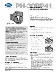
Pintle Hooks – Rigid Mount<br />
PH-10RP41<br />
Application<br />
A rigid mount pintle hook designed for over-the-road<br />
and off-road towing.<br />
Mounting Dimensions<br />
5.39˝<br />
Cast steel body is heat<br />
treated for strength<br />
and durability.<br />
One-hand operation and<br />
automatic secondary lock<br />
Patent #7,431,321<br />
TM<br />
5.81˝<br />
3.75˝<br />
The hook is designed<br />
for maximum<br />
articulation and<br />
reduced wear.<br />
1.63˝<br />
1.69˝<br />
4.50˝<br />
3.38˝<br />
Available with a<br />
tethered lock pin<br />
as PH-10RP51<br />
.53˝<br />
Weight: 7.5 lbs. (3.4 kg)<br />
1.75˝<br />
Capacities<br />
2,000 lbs. (910 kg) Maximum Vertical Load<br />
10,000 lbs. (4,540 kg) Maximum Gross Trailer Weight<br />
Drawbar Eye Dimensions<br />
2˝ to 3˝ I.D. with 1.25˝ to 1.63˝ diameter section.<br />
Additional Information<br />
• For severe off-road applications, reduce the above maximum<br />
capacities by 25% and use with a swivel-mount drawbar.<br />
• Tested in accordance with SAE J847.<br />
• For additional specification detail, refer to document number<br />
<strong>XL</strong>-PH350. For PH-10RP51, refer to <strong>XL</strong>-PH387.<br />
Replacement Parts<br />
For PH-10RP41 use RK-10632<br />
For PH-10RP51<br />
use RK-10632-1<br />
XB-T-89-4<br />
XB-11048<br />
.25˝<br />
XB-11157<br />
XB-T-89-4<br />
XB-11048<br />
<strong>XL</strong>-<strong>PH10397SG</strong>-en-US Rev C 02-2013<br />
Amendments and errors reserved. © SAF-HOLLAND, Inc.<br />
9
Pintle Hooks – Rigid Mount<br />
PH-T-60-AOL-8 (with chained cotter pin)<br />
PH-T-60-S10646 (with tethered lock pin)<br />
Application<br />
A rigid mount pintle hook designed for over-the-road and<br />
off-road towing within stated capacities.<br />
Mounting Dimensions<br />
Forged from a special steel<br />
alloy that is heat treated<br />
for strength and durability.<br />
The latch is forged steel<br />
alloy and heat treated for<br />
strength and long life.<br />
1.88˝<br />
7.42˝<br />
6.38˝<br />
4.50˝<br />
3.38˝<br />
1.69˝<br />
Available with a<br />
tethered lock pin<br />
as PH-T-60-S10646<br />
Weight: 11 lbs. (5 kg)<br />
1.75˝<br />
Capacities<br />
6,000 lbs. (2,720 kg) Maximum Vertical Load<br />
30,000 lbs. (13,610 kg) Maximum Gross Trailer Weight<br />
Drawbar Eye Dimensions<br />
2˝ to 3˝ I.D. with 1.25˝ to 1.63˝ diameter section.<br />
Additional Information<br />
• For severe off-road applications, reduce the above maximum<br />
capacities by 25% and use with a swivel-mount drawbar.<br />
• Tested in accordance with SAE J847.<br />
• For additional specification detail, refer to document number<br />
<strong>XL</strong>-PH203, or <strong>XL</strong>-PH333 for PH-T-60-S10646.<br />
.53˝ DIA.<br />
Replacement Parts<br />
For PH-T-60-AOL-8 use RK-62-O<br />
XB-T-89-4<br />
For PH-T-60-S10646 use RK-S10646<br />
XB-11048<br />
XA-199-1<br />
XB-11048<br />
XB-T-89-4<br />
XB-11157<br />
10 <strong>XL</strong>-<strong>PH10397SG</strong>-en-US Rev C 02-2013 Amendments and errors reserved. © SAF-HOLLAND, Inc.
Pintle Hooks – Rigid Mount<br />
PH-30RP41<br />
Application<br />
A versatile rigid mount pintle hook designed for over-the-road and<br />
off-road towing.<br />
Mounting Dimensions<br />
5.39˝<br />
One-hand operation and<br />
automatic secondary lock<br />
Patent #7,431,321<br />
TM<br />
5.81˝<br />
The hook is<br />
designed for<br />
maximum<br />
articulation and<br />
reduced wear.<br />
1.94˝<br />
5.69˝<br />
Forged from a special steel<br />
alloy that is heat treated<br />
for strength and durability.<br />
Available<br />
with a<br />
tethered<br />
lock pin as<br />
PH-30RP51<br />
4.50˝<br />
3.38˝<br />
1.69˝<br />
.53˝<br />
Weight: 8.4 lbs. (4.2 kg)<br />
1.75˝<br />
Capacities<br />
6,000 lbs. (2,720 kg) Maximum Vertical Load<br />
30,000 lbs. (13,610 kg) Maximum Gross Trailer Weight<br />
Drawbar Eye Dimensions<br />
2.38˝ to 3˝ I.D. with 1.25˝ to 1.63˝ diameter section.<br />
Additional Information<br />
• For severe off-road applications, reduce the above maximum<br />
capacities by 25% and use with a swivel-mount drawbar.<br />
• Tested in accordance with SAE J847.<br />
• For additional specification detail, refer to document number<br />
<strong>XL</strong>-PH351. For PH-30RP51, refer to <strong>XL</strong>-PH364.<br />
Replacement Parts<br />
For PH30RP41 use RK-10632<br />
For PH-30RP51 use RK-10632-1<br />
.25˝<br />
XB-T-89-4<br />
XB-11048<br />
XB-11157<br />
XB-T-89-4<br />
XB-11048<br />
<strong>XL</strong>-<strong>PH10397SG</strong>-en-US Rev C 02-2013<br />
Amendments and errors reserved. © SAF-HOLLAND, Inc.<br />
11
Pintle Hooks – Swivel Mount (with Spring Shock Absorption)<br />
PH-30SA41<br />
Application<br />
A split flange mount, swivel style pintle hook designed for over-the-road and<br />
off-road applications. The spring provides shock absorption at the coupling—<br />
ideal for utility and construction applications.<br />
Mounting Dimensions<br />
.63˝<br />
MAX.<br />
6.75˝<br />
One-hand operation and<br />
automatic secondary lock<br />
Patent #7,431,321<br />
TM<br />
Forged from a special steel<br />
alloy that is heat treated for<br />
strength and durability.<br />
16˝<br />
9.25˝<br />
.53˝<br />
4.50˝<br />
2.25˝<br />
A steel spring provides<br />
shock absorption.<br />
2˝<br />
Cast ductile iron mounting<br />
flanges for max. 5/8˝ plate.<br />
Weight: 32 lbs. (14.5kg)<br />
Available with<br />
a tethered<br />
lock pin as<br />
PH-30SA51.<br />
4.25˝<br />
2.50˝<br />
8˝<br />
4˝<br />
1˝<br />
5.88˝<br />
Capacities<br />
6,000 lbs. (2,720 kg) Maximum Vertical Load<br />
30,000 lbs. (13,610 kg) Maximum Gross Trailer Weight<br />
Drawbar Eye Dimensions<br />
2.38˝ to 3˝ I.D. with 1.25˝ to 1.63˝ diameter section.<br />
Additional Information<br />
• For severe off-road applications, reduce the above maximum<br />
capacities by 25%. Not for use with a swivel-mount drawbar.<br />
• Tested in accordance with SAE J847.<br />
• For additional specification detail, refer to document number<br />
<strong>XL</strong>-PH368. For PH-30SA51, refer to <strong>XL</strong>-PH369.<br />
Replacement Parts<br />
For PH-30SA41 use RK-10632<br />
XB-T-89-4<br />
XB-11048<br />
For PH-30SA51<br />
use RK-10632-1<br />
XB-11157<br />
XB-T-89-4<br />
XB-11048<br />
PH-30SE41<br />
XA-10802-R<br />
XA-10802-F<br />
XB-T-60<br />
XB-T-9N<br />
XA-T-56<br />
Available with a<br />
tethered lock pin<br />
as PH-30SE51.<br />
XB-767<br />
XB-T-52<br />
12 <strong>XL</strong>-<strong>PH10397SG</strong>-en-US Rev C 02-2013 Amendments and errors reserved. © SAF-HOLLAND, Inc.
Pintle Hooks – Swivel Mount (with Spring Shock Absorption)<br />
PH-30SB41<br />
Application<br />
An under-mount, swivel style pintle hook designed for over-the-road<br />
and off-road applications. The spring provides shock absorption at the<br />
coupling—ideal for utility and construction applications.<br />
Mounting Dimensions<br />
9.44˝<br />
Fully machined,<br />
high-strength, cast ductile<br />
iron housing with a zerk<br />
fitting for easy lubrication.<br />
One-hand operation and<br />
automatic secondary lock<br />
Patent #7,431,321<br />
TM<br />
.94˝<br />
16˝<br />
BRACE LUG<br />
ATTACHMENT<br />
Steel spring<br />
provides shock<br />
absorption.<br />
12˝<br />
10.38˝<br />
7.88˝<br />
5.19˝<br />
2.5˝<br />
.81˝<br />
1.75˝<br />
Integrated mount<br />
for cross-bracing.<br />
Weight: 38 lbs. (17.2 kg)<br />
Available<br />
with a<br />
tethered<br />
lock pin as<br />
PH-30SB51<br />
10.19˝<br />
1.25˝<br />
Capacities<br />
6,000 lbs. (2,720 kg) Maximum Vertical Load<br />
30,000 lbs. (13,610 kg) Maximum Gross Trailer Weight<br />
Drawbar Eye Dimensions<br />
2.38˝ to 3˝ I.D. with 1.25˝ to 1.63˝ diameter section.<br />
Additional Information<br />
• For severe off-road applications, reduce the above maximum<br />
capacities by 25%. Not for use with a swivel-mount drawbar.<br />
• Tested in accordance with SAE J847.<br />
• For additional specification detail, refer to document number<br />
<strong>XL</strong>-PH365. For PH-30SB51, refer to <strong>XL</strong>-PH371.<br />
Replacement Parts<br />
RK-10632<br />
XB-T-89-4<br />
XB-T-69-C<br />
For PH-30SB51<br />
use RK-10632-1<br />
XB-11157<br />
XB-T-89-4<br />
XB-11048<br />
XB-T-60<br />
PH-30SE41<br />
XB-T-9N<br />
Available with a<br />
tethered lock pin<br />
as PH-30SE51.<br />
XB-T-52<br />
XA-10891<br />
XA-T-56<br />
<strong>XL</strong>-<strong>PH10397SG</strong>-en-US Rev C 02-2013<br />
Amendments and errors reserved. © SAF-HOLLAND, Inc.<br />
13
Pintle Hooks – Swivel Mount<br />
PH-T-60-AOS-L-8<br />
Application<br />
A split flange mounted, swivel style pintle hook designed for over-the-road<br />
and off-road applications.<br />
Mounting Dimensions<br />
The body is forged from special alloy steel that is heat treated for<br />
strength and durability. The special pintle shape is designed for maximum<br />
articulation and reduced wear.<br />
4.67˝<br />
2.95˝<br />
The rear flange<br />
includes a grease<br />
fitting for easy<br />
lubrication.<br />
Latch is forged steel alloy and heat<br />
treated for strength and long life.<br />
.69˝<br />
MAX.<br />
1.88˝<br />
2.68˝<br />
4.00˝<br />
6.16˝<br />
Mounting flanges<br />
allow for a maximum<br />
11/16˝ plate.<br />
1.44˝<br />
2.88˝<br />
4.50˝<br />
2.25˝<br />
MIN. CLEAR<br />
AREA<br />
.88˝<br />
1.75˝<br />
Weight: 15 lbs. (6.8 kg)<br />
1.69˝<br />
.53˝ HOLES<br />
3.38˝ 1.28˝ DIA. HOL E<br />
Capacities<br />
3,600 lbs. (1,630 kg) Maximum Vertical Load<br />
18,000 lbs. (8,160 kg) Maximum Gross Trailer Weight<br />
Drawbar Eye Dimensions<br />
2˝ to 3˝ I.D. with 1.25˝ to 1.63˝ diameter section.<br />
Additional Information<br />
• For severe off-road applications, reduce the above maximum<br />
capacities by 25%. Not for use with a swivel-mount drawbar.<br />
• Tested in accordance with SAE J847.<br />
• For additional specification detail, refer to<br />
document number <strong>XL</strong>-PH208.<br />
Replacement Parts<br />
XB-T-20-2<br />
XA-T-88<br />
XB-773<br />
XB-767<br />
RK-T-61<br />
XB-T-45-1<br />
(Qty. 4)<br />
XB-758<br />
(Qty. 4)<br />
XB-T-89<br />
(Qty. 4)<br />
RK-62-O<br />
XB-T-89-4<br />
XB-11048<br />
XA-199-1<br />
14 <strong>XL</strong>-<strong>PH10397SG</strong>-en-US Rev C 02-2013 Amendments and errors reserved. © SAF-HOLLAND, Inc.
Pintle Hooks – Swivel Mount<br />
PH-760<br />
Application<br />
Heavy-duty construction for on- and off-road applications where a<br />
significant amount of articulation is required.<br />
Mounting Dimensions<br />
1.50˝<br />
To ensure long life, the front<br />
and rear flanges and pivot<br />
bolt include zerk fittings for<br />
for easy lubrication.<br />
Mounting flanges allow for<br />
a maximum 3/4˝ plate.<br />
The forged steel<br />
alloy body and<br />
the cast steel latch<br />
are heat treated<br />
for strength and<br />
durability.<br />
2.00˝<br />
4.19˝<br />
.75˝<br />
4.25˝<br />
13.7˝<br />
8.50˝<br />
8.75˝<br />
1.81˝<br />
7.6˝<br />
MIN. CLEAR<br />
AREA<br />
The hook is<br />
designed for<br />
maximum<br />
articulation.<br />
4.00˝<br />
.78˝ DIA.<br />
(2 HOLES REQ.)<br />
3.25˝ 1.88˝ DIA. HOL E<br />
3.25˝ 6.50˝<br />
Weight: 36 lbs. (16.3 kg)<br />
3.50˝<br />
Capacities<br />
9,800 lbs. (4,440 kg) Maximum Vertical Load<br />
49,000 lbs. (22,230 kg) Maximum Gross Trailer Weight<br />
Drawbar Eye Dimensions<br />
3˝ I.D. with 1.25˝ to 1.63˝ diameter section.<br />
Additional Information<br />
• For severe off-road applications, reduce the above maximum<br />
capacities by 25%. Not for use with a swivel-mount drawbar.<br />
• Tested in accordance with SAE J847.<br />
• For additional specification detail, refer to document<br />
number <strong>XL</strong>-PH215.<br />
4.12˝<br />
Replacement Parts<br />
XB-T-60<br />
XB-HNH-34-F<br />
(Qty. 2)<br />
XA-763A<br />
RK-05961<br />
XA-08636<br />
XB-T-60<br />
XB-10089<br />
XB-127<br />
RK-02772<br />
XB-767<br />
(Qty. 2)<br />
8.50˝<br />
.75<br />
BOLTS<br />
(2 REQ.)<br />
XB-10089<br />
XA-763<br />
XB-773<br />
XB-772<br />
(Qty. 2)<br />
XB-771-1<br />
XB-128<br />
XA-768<br />
XA-199-6<br />
(SUB-ASSY.)<br />
XA-08636<br />
(SUB-ASSY.)<br />
<strong>XL</strong>-<strong>PH10397SG</strong>-en-US Rev C 02-2013<br />
Amendments and errors reserved. © SAF-HOLLAND, Inc.<br />
15
Pintle Hooks – Swivel Mount<br />
PH-775-01552 (Lubricated)<br />
Application<br />
Mounting Dimensions<br />
Heavy-duty construction for on- and off-road applications where a<br />
significant amount of articulation is required.<br />
Grease fitting for<br />
easy lubrication.<br />
Cast steel alloy latch is<br />
heat treated for strength<br />
and durability.<br />
1.75˝<br />
5.12˝<br />
4.38˝<br />
6.56˝ 8.44˝<br />
6.25˝<br />
4.50˝<br />
2.25˝<br />
A one piece housing<br />
keeps contaminants<br />
from entering the<br />
pintle hook assembly.<br />
2.25˝<br />
4.50˝<br />
6.25˝<br />
Weight: 60 lbs. (27.2 kg)<br />
Body and housing are forged from<br />
special steel alloy and heat treated for<br />
high strength, and wear resistance.<br />
.94˝ DIA.<br />
(4 HOLES)<br />
3.25˝<br />
3.25˝<br />
6.50˝MIN. CLEAR AREA<br />
2.25˝<br />
Capacities<br />
20,000 lbs. (9,070 kg) Maximum Vertical Load<br />
100,000 lbs. (45,360 kg) Maximum Gross Trailer Weight<br />
Drawbar Eye Dimensions<br />
3˝ I.D. with 1.63˝ diameter section.<br />
Additional Information<br />
• For severe off-road applications, reduce the above maximum<br />
capacities by 25%. Not for use with a swivel-mount drawbar.<br />
• Tested in accordance with SAE J847.<br />
• For additional specification detail, refer to document<br />
number <strong>XL</strong>-PH246.<br />
.28 X 45°<br />
CHAMFER<br />
6.50˝<br />
4.00˝ DIA. HOLE<br />
2.25˝<br />
4.50˝<br />
Replacement Parts<br />
XB-E-552-1<br />
XB-767-10<br />
XB-757<br />
XB-120-2<br />
XB-127<br />
4.50˝<br />
.94˝ DIA.<br />
(4 HOLES)<br />
RK-775<br />
LATCH KIT<br />
XA-766-2Z<br />
XB-781-1<br />
The Holland PH-775-01552 complies with NOM-035-SCT-2-2010<br />
Safety Specifications and Test Methods.<br />
XA-749-2<br />
XA-782<br />
Interchangeable with<br />
New PH-995SH71,<br />
see page 33.<br />
PH-775-01552-1<br />
XA-199-4<br />
XB-780-1<br />
16<br />
<strong>XL</strong>-<strong>PH10397SG</strong>-en-US Rev C 02-2013<br />
Amendments and errors reserved. © SAF-HOLLAND, Inc.
Pintle Hooks – Swivel Mount<br />
PH-775SL11 (NoLube ® )<br />
Application<br />
Mounting Dimensions<br />
Heavy-duty construction for on- and off-road applications where a<br />
significant amount of articulation is required.<br />
A one-piece sealed housing keeps<br />
contaminants from entering the<br />
pintle hook assembly.<br />
One-hand operation and<br />
automatic secondary lock<br />
Patent #7,431,321<br />
TM<br />
4.00 MAX<br />
1.75<br />
5.27˝SQ.<br />
4.43˝<br />
Cast steel alloy latch is<br />
heat treated for strength<br />
and durability.<br />
6.74˝<br />
6.62˝<br />
4.50˝<br />
2.25˝<br />
SQ.<br />
8.26˝<br />
4.50˝<br />
2.25˝<br />
SQ.<br />
6.62˝<br />
Body and housing are forged<br />
from special steel alloy and<br />
heat treated for high strength<br />
and wear resistance.<br />
Weight: 57 lbs. (25.8 kg)<br />
Capacities<br />
20,000 lbs. (9,070 kg) Maximum Vertical Load<br />
100,000 lbs. (45,360 kg) Maximum Gross Trailer Weight<br />
Drawbar Eye Dimensions<br />
3˝ I.D. with a 1.63˝ diameter section.<br />
Additional Information<br />
• For severe off-road applications, reduce the above maximum<br />
capacities by 25%. Not for use with a swivel-mount drawbar.<br />
• Tested in accordance with SAE J847.<br />
• For additional specification detail, refer to document<br />
number <strong>XL</strong>-PH334. For PH-775SL21, refer to <strong>XL</strong>-PH339.<br />
®<br />
No lubrication required.<br />
Available with<br />
a tethered<br />
lock pin as<br />
PH-775SL21.<br />
0.91˝<br />
4 HOLES<br />
4.03˝ THRU<br />
WITH .28˝x 45˚<br />
CHAMFER GAP<br />
HOUSING<br />
PROFILE<br />
REF<br />
C L<br />
6.75˝ SQ.<br />
3.38˝<br />
SQ.<br />
C L<br />
Replacement Parts<br />
RK-10545 LATCH KIT<br />
XB-10537<br />
XB-03104<br />
RK-11510<br />
Seal Kit<br />
XA-10546<br />
Housing Subassembly<br />
MIN. CLEARANCE<br />
.94˝<br />
DIA.<br />
2.25˝ SQ.<br />
4.50˝ TYP. SQ.<br />
For PH-775SL21 use<br />
RK-10545-1 LATCH KIT<br />
XB-10537<br />
XB-S10647<br />
XB-03104<br />
The Holland PH-775SL NoLube complies with NOM-0350-SCT-2-2010<br />
Safety Specifications and Test Methods.<br />
PH-775SN11<br />
Hook Subassembly<br />
XA-782*<br />
XB-781-1*<br />
XA-780-1*<br />
PH-775SN21<br />
Hook Subassembly<br />
* Included in<br />
Hook<br />
Subassemblies<br />
<strong>XL</strong>-<strong>PH10397SG</strong>-en-US Rev C 02-2013<br />
Amendments and errors reserved. © SAF-HOLLAND, Inc.<br />
17
Pintle Hooks – Rigid Mount – Air Cushioned<br />
PH-300 and PH-300-R<br />
Application<br />
Mounting Dimensions<br />
A rigid mount pintle hook designed for enhanced wear resistance. Used<br />
for on- and off-road applications.<br />
Unique one-hand latch operation.<br />
Also available with reversed latch<br />
handle, PH-300-R (see inset).<br />
Plunger/snubber force is<br />
developed by the vehicle’s air<br />
system to reduce wear and to<br />
provide shock absorption.<br />
5.76˝<br />
.38˝ MIN .<br />
2.00˝ MAX.<br />
7.25˝<br />
10.5˝<br />
Adjustable<br />
plunger<br />
6.00˝<br />
3.8˝<br />
.94˝<br />
Austenitic Manganese<br />
steel alloy body<br />
for enhanced wear<br />
resistance.<br />
PH-300-R<br />
(reverse latch)<br />
3/8˝ to 1/4”<br />
NPT Reducer<br />
3/8˝NPT Plug<br />
7.5˝<br />
3.25˝<br />
DIA. MIN<br />
*.<br />
1.88˝<br />
3.75˝<br />
.69˝<br />
3.75˝<br />
.12˝<br />
6.00˝<br />
2.5˝<br />
Weight: 42 lbs. (19 kg)<br />
The complete assembly includes a pintle hook, plunger, air chamber, and<br />
mounting bracket. For pintle hooks without an air chamber, bracket, or<br />
plunger, order PH-300-1 or PH-300-R-1.<br />
The PH-300 can be operated with or without the air chamber. For easier<br />
coupling, drawbar guides are available, see page 56.<br />
3.00˝<br />
6.00˝<br />
* Center hole not required if<br />
used without air chamber.<br />
.81˝ DIA. TYP.<br />
(6 REQ.)<br />
Capacities<br />
18,000 lbs. (8,160 kg) Maximum Vertical Load<br />
72,000 lbs. (32,660 kg) Maximum Gross Trailer Weight<br />
Replacement Parts<br />
PH-300 use RK-02536<br />
PH-300-R use RK-03179<br />
Drawbar Eye Dimensions<br />
2.38˝ to 3˝ I.D. with 1.25˝ to 1.63˝ diameter section.<br />
XB-03104<br />
XB-03104<br />
Additional Information<br />
XB-03103<br />
• For severe off-road applications, reduce the above maximum<br />
capacities by 25% and use with a swivel-mount drawbar.<br />
• Tested in accordance with SAE J847 (Type II).<br />
• For additional specification detail, refer to document<br />
number <strong>XL</strong>-PH243. For PH-300-R, refer to <strong>XL</strong>-PH248.<br />
XB-165945<br />
XB-T-199<br />
Included with<br />
XB-165945<br />
XA-04156<br />
XE-01544-1<br />
XB-T-199<br />
Included with<br />
XB-165945<br />
XA-02608 Cylinder and Bracket Sub-Assembly<br />
18<br />
<strong>XL</strong>-<strong>PH10397SG</strong>-en-US Rev C 02-2013<br />
Amendments and errors reserved. © SAF-HOLLAND, Inc.
Pintle Hooks – Rigid Mount – Air Cushioned<br />
PH-210<br />
Application<br />
A rigid mount pintle hook designed for trailers and semitrailers in doubles<br />
and triples operations. Used for off- and over-the-road applications. Air<br />
cushioned snubber is designed to minimize the gap between the pintle<br />
hook and the drawbar eye on vehicles with air systems.<br />
Plunger/snubber force is developed by<br />
the vehicle’s air system to reduce wear<br />
and to provide shock absorption.<br />
One-hand operation and<br />
automatic secondary lock<br />
Patent #7,431,321<br />
TM<br />
Mounting Dimensions<br />
5.97˝ 7.06˝<br />
3/8˝ MIN<br />
2˝ MAX<br />
5.64˝<br />
.95˝<br />
10.71˝<br />
3.93˝<br />
Air chambers<br />
are available<br />
for different<br />
mounting<br />
widths; see<br />
page 26.<br />
Weight: 38 lbs. (17.2 kg)<br />
Capacities<br />
Adjustable plunger<br />
18,000 lbs. Maximum Vertical Load<br />
90,000 lbs. Maximum Gross Trailer Weight<br />
Cast steel alloy body is<br />
heat treated for increased<br />
strength and durability.<br />
PH-210RA11 – Complete assembly includes a pintle hook, plunger,<br />
air chamber, and mounting bracket.<br />
PH-210RN11 – Pintle hook without an air chamber, bracket or plunger.<br />
PH-210RM11 – Pintle hook with plunger only.<br />
For additional model numbers, see page 26.<br />
The PH-210 can be operated with or without the air chamber.<br />
For easier coupling, drawbar guides are available, see page 56.<br />
Available with a<br />
tethered lock pin.<br />
(Replace “11” with “21”<br />
in model number)<br />
3/8˝ NPT PLUG<br />
3/8˝ TO 1/4˝ NPT REDUCER<br />
3.25˝<br />
DIA.<br />
MIN.<br />
*<br />
3.00˝<br />
1.88˝<br />
6.50˝<br />
Replacement Parts<br />
.63˝<br />
8.5˝<br />
5.25˝<br />
2.62˝<br />
3.25˝<br />
* Center hole not required if<br />
used without air chamber.<br />
4.25˝<br />
3.14˝<br />
5.64˝<br />
.81˝ DIA.<br />
TYP.<br />
(4 REQ.)<br />
Drawbar Eye Dimensions<br />
2.38˝ to 3˝ I.D. with 1.25˝ to 1.63˝ diameter section.<br />
Additional Information<br />
• For severe off-road applications, reduce the above maximum<br />
capacities by 25% and use with a swivel-mount drawbar.<br />
• Tested in accordance with SAE J847.<br />
• For additional specification detail, refer to document<br />
number <strong>XL</strong>-PH340.<br />
• Also available – PH210 Series with tethered lock pin.<br />
Replace “11” with “21” in model number.<br />
RK-10545 LATCH KIT<br />
XB-10537<br />
XB-03104<br />
XB-165945<br />
For PH-210RN21 use<br />
RK-10545-1 LATCH KIT<br />
XB-S10647<br />
XB-03104<br />
XB-T-199<br />
XB-10537<br />
Included with<br />
XB-165945<br />
XA-04156<br />
The Holland PH-210 complies with NOM-0350-SCT-2-2010<br />
Safety Specifications and Test Methods.<br />
XE-01544-1<br />
XB-T-199<br />
Included with<br />
XB-165945<br />
XA-02608 Cylinder and Bracket Sub-Assembly<br />
<strong>XL</strong>-<strong>PH10397SG</strong>-en-US Rev C 02-2013<br />
Amendments and errors reserved. © SAF-HOLLAND, Inc.<br />
19
Pintle Hooks – Rigid Mount – Air Cushioned<br />
PH-310<br />
Application<br />
A rigid mount pintle hook designed for trailers and semitrailers in doubles<br />
and triples operations. Used for off- and over-the-road applications. Air<br />
cushioned snubber is designed to minimize the space between the pintle<br />
hook and the drawbar eye on vehicles with air systems.<br />
Mounting Dimensions<br />
5.97˝<br />
3/8˝ MIN<br />
2˝ MAX<br />
7.06˝<br />
Plunger/snubber force is developed by<br />
the vehicle’s air system to reduce wear<br />
and to provide shock absorption.<br />
One-hand operation and<br />
automatic secondary lock<br />
Patent #7,431,321<br />
TM<br />
6.11˝<br />
.95˝<br />
10.71˝<br />
3.93˝<br />
Air chambers<br />
are available<br />
for different<br />
mounting<br />
widths; see<br />
page 26.<br />
Available with a<br />
tethered lock pin.<br />
(Replace “11” with “21”<br />
in model number)<br />
Adjustable plunger<br />
Cast steel alloy body is<br />
heat treated for increased<br />
Weight: 39 lbs. (17.7 kg)<br />
strength, durability, and<br />
wear resistance.<br />
PH-310RA11 – Complete assembly includes a pintle hook,<br />
plunger, air chamber, and mounting bracket.<br />
PH-310RN11 – Pintle hook without an air chamber, bracket or plunger.<br />
PH-310RM11 – Pintle hook with plunger only.<br />
For additional model numbers, see page 26.<br />
The PH-310 can be operated with or without the air chamber.<br />
For easier coupling, drawbar guides are available, see page 56.<br />
3/8˝ NPT PLUG<br />
3/8˝ TO 1/4˝ NPT REDUCER<br />
3.75˝<br />
1.88˝<br />
7.75˝<br />
3.25˝ MIN. 3.75˝<br />
*<br />
3.00˝<br />
6.00˝<br />
* Center hole not required if<br />
used without air chamber.<br />
.63˝<br />
.12˝<br />
6.11˝<br />
3.13˝<br />
.81 TYP<br />
(6 REQ.)<br />
Capacities<br />
20,000 lbs. (9,070 kg) Maximum Vertical Load<br />
100,000 lbs. (45,360 kg) Maximum Gross Trailer Weight<br />
Drawbar Eye Dimensions<br />
2.38˝ to 3˝ I.D. with 1.25˝ to 1.63˝ diameter section.<br />
Replacement Parts<br />
RK-10545 LATCH KIT<br />
XB-10537<br />
For PH-310RN21 use<br />
RK-10545-1 LATCH KIT<br />
XB-S10647<br />
XB-03104<br />
Additional Information<br />
• For severe off-road applications, reduce the above maximum<br />
capacities by 25% and use with a swivel-mount drawbar.<br />
• Tested in accordance with SAE J847.<br />
• For additional specification detail, refer to document<br />
number <strong>XL</strong>-PH341.<br />
• Also available – PH310 Series with tethered lock pin.<br />
Replace “11” with “21” in model number.<br />
The Holland PH-310 complies with NOM-0350-SCT-2-2010<br />
Safety Specifications and Test Methods.<br />
XB-03104<br />
XE-01544-1<br />
XB-165945<br />
XB-T-199<br />
XB-T-199<br />
XB-10537<br />
Included with<br />
XB-165945<br />
XA-04156<br />
Included with<br />
XB-165945<br />
XA-02608 Cylinder and Bracket Sub-Assembly<br />
20 <strong>XL</strong>-<strong>PH10397SG</strong>-en-US Rev C 02-2013 Amendments and errors reserved. © SAF-HOLLAND, Inc.
Pintle Hooks – Rigid Mount – Air Cushioned<br />
PH-400 and PH-400-H<br />
Application<br />
A rigid mount pintle hook designed for trailers and semitrailers in doubles<br />
and triples operations. Used for off- and over-the-road applications. Air<br />
cushioned snubber is designed to minimize the gap between the pintle<br />
hook and the drawbar eye on vehicles with air systems.<br />
Automatic secondary lock<br />
for improved <strong>saf</strong>ety.<br />
Plunger/snubber<br />
force is developed<br />
by the vehicle’s<br />
air system to<br />
reduce wear and<br />
to provide shock<br />
absorption.<br />
Air chambers<br />
are available<br />
for different<br />
mounting widths;<br />
see page 26.<br />
Weight: 48 lbs. (21.8 kg)<br />
The complete assembly includes a pintle hook, plunger, air chamber, and mounting<br />
bracket. For pintle hooks without an air chamber, bracket, or plunger, order PH-400-1<br />
or PH-400-1-H.<br />
The PH-400 and PH-400-H can be operated with or without the air chamber. For<br />
easier coupling, drawbar guides are available, see page 56.<br />
Capacities<br />
20,000 lbs. (9,070 kg) Maximum Vertical Load<br />
100,000 lbs. (45,360 kg) Maximum Gross Trailer Weight<br />
Drawbar Eye Dimensions<br />
2.38˝ to 3˝ I.D. with 1.25˝ to 1.63˝ diameter section.<br />
Additional Information<br />
Adjustable plunger<br />
Unique one-hand<br />
latch operation.<br />
• For severe off-road applications, reduce the above maximum<br />
capacities by 25% and use with a swivel-mount drawbar.<br />
• Tested in accordance with SAE J847.<br />
• For additional specification detail, refer to document<br />
number <strong>XL</strong>-PH244 or PH-247.<br />
Cast alloy<br />
steel body is<br />
heat treated<br />
for increased<br />
strength,<br />
durability,<br />
and wear<br />
resistance.<br />
The Holland PH-400 and PH-400-H complies with NOM-0350-SCT-2-2010<br />
Safety Specifications and Test Methods.<br />
Mounting Dimensions<br />
PH-400 and PH-400-H<br />
6.62˝<br />
2.38˝<br />
2.12˝<br />
10.43˝<br />
11.75˝<br />
5.00˝<br />
PH-400<br />
7.6˝<br />
3.8˝<br />
3.25˝ DIA. MIN<br />
2.50˝5.00˝<br />
2.00˝<br />
1.06˝<br />
5.00˝<br />
10.43˝<br />
.81˝ DIA. TYP.<br />
(8 REQ.)<br />
Replacement Parts<br />
RK-02536<br />
*<br />
XB-03103<br />
XB-03104<br />
XE-01544-1<br />
5.76˝<br />
.75˝ MIN .<br />
2.25˝ MAX.<br />
3.8˝ to 1/4”<br />
NPT Reducer<br />
3.8˝NPT Plug<br />
* Center hole not required if<br />
used without air chamber.<br />
XB-165945<br />
3.25˝<br />
DIA. MIN.<br />
6.38˝<br />
*<br />
2.19˝<br />
2.38˝<br />
3.00˝<br />
XB-T-199<br />
XB-T-199<br />
.63˝<br />
7.00˝<br />
PH-400-H<br />
2.50˝<br />
7.6˝<br />
5.00˝<br />
6.00˝<br />
3.8˝<br />
Included with<br />
XB-165945<br />
XA-04156<br />
.94˝<br />
10.43˝<br />
1.81˝<br />
5.00˝<br />
.81˝ DIA. TYP.<br />
(8 REQ.)<br />
Included with<br />
XB-165945<br />
XA-02608 Cylinder and Bracket Sub-Assembly<br />
<strong>XL</strong>-<strong>PH10397SG</strong>-en-US Rev C 02-2013<br />
Amendments and errors reserved. © SAF-HOLLAND, Inc.<br />
21
Pintle Hooks – Rigid Mount – Air Cushioned<br />
PH-410<br />
Application<br />
A rigid mount pintle hook designed for trailers and semitrailers in doubles<br />
and triples operations. Used for off- and over-the-road applications. Air<br />
cushioned snubber is designed to minimize the gap between the pintle<br />
hook and the drawbar eye on vehicles with air systems.<br />
Plunger/snubber force is developed by<br />
the vehicle’s air system to reduce wear<br />
and to provide shock absorption.<br />
One-hand operation and<br />
automatic secondary lock<br />
Patent #7,431,321<br />
TM<br />
Mounting Dimensions<br />
5.97˝<br />
3/8˝ MIN<br />
2˝ MAX<br />
7.70˝<br />
7.06˝<br />
.94˝<br />
11.79˝<br />
Air chambers<br />
are available<br />
for different<br />
mounting widths;<br />
see page 26.<br />
Adjustable plunger<br />
Weight: 42 lbs. (19 kg)<br />
Available with a<br />
tethered lock pin.<br />
(Replace “11” with “21”<br />
in model number)<br />
Cast steel alloy body is<br />
heat treated for increased<br />
strength, durability, and<br />
wear resistance.<br />
PH-410RA11 – Complete assembly includes a pintle hook,<br />
plunger, air chamber, and mounting bracket.<br />
PH-410RN11 – Pintle hook without an air chamber, bracket or plunger.<br />
PH-410RM11 – Pintle hook with plunger only.<br />
For additional model numbers, see page 26.<br />
The PH-410 can be operated with or without the air chamber.<br />
For easier coupling, drawbar guides are available, see page 56.<br />
3/8˝ NPT PLUG<br />
3/8˝ TO 1/4˝<br />
NPT REDUCER<br />
3.25˝ MIN.<br />
*<br />
5.00˝<br />
.81˝ THRU<br />
(6 REQ.)<br />
* Center hole not required if<br />
used without air chamber.<br />
.63˝<br />
7.63˝<br />
5.00˝<br />
2.50˝<br />
3.81˝<br />
2.38˝<br />
2.00˝<br />
2.13˝<br />
4.94˝<br />
Capacities<br />
20,000 lbs. (9,070 kg) Maximum Vertical Load<br />
100,000 lbs. (45,360 kg) Maximum Gross Trailer Weight<br />
Drawbar Eye Dimensions<br />
2.38˝ to 3˝ I.D. with 1.25˝ to 1.63˝ diameter section.<br />
Replacement Parts<br />
RK-10545 LATCH KIT<br />
XB-10537<br />
For PH-410RN21 use<br />
RK-10545-1 LATCH KIT<br />
XB-S10647<br />
XB-03104<br />
Additional Information<br />
• For severe off-road applications, reduce the above maximum<br />
capacities by 25% and use with a swivel-mount drawbar.<br />
• Tested in accordance with SAE J847.<br />
• For additional specification detail, refer to document number<br />
<strong>XL</strong>-PH342.<br />
• Also available – PH410 Series with tethered lock pin. Replace<br />
“11” with “21” in model number.<br />
XB-03104<br />
XB-165945<br />
XB-T-199<br />
XB-10537<br />
Included with<br />
XB-165945<br />
XA-04156<br />
The Holland PH-410 complies with NOM-0350-SCT-2-2010<br />
Safety Specifications and Test Methods.<br />
XE-01544-1<br />
XB-T-199<br />
Included with<br />
XB-165945<br />
XA-02608 Cylinder and Bracket Sub-Assembly<br />
22 <strong>XL</strong>-<strong>PH10397SG</strong>-en-US Rev C 02-2013 Amendments and errors reserved. © SAF-HOLLAND, Inc.
Pintle Hooks – Rigid Mount – Air Cushioned<br />
PH-550<br />
Application<br />
A rigid mount pintle hook designed for trailers and semitrailers in doubles<br />
and triples operations. Used for off- and over-the-road applications. Air<br />
cushioned snubber is designed to minimize the gap between the pintle<br />
hook and the drawbar eye on vehicles with air systems.<br />
Mounting Dimensions<br />
5.8˝<br />
.50˝ MIN.<br />
2.25˝ MAX.<br />
6.7˝<br />
Plunger/snubber force is developed by<br />
the vehicle’s air system to reduce wear<br />
and to provide shock absorption.<br />
Secondary lock pin.<br />
10.7˝<br />
9.9˝<br />
.38˝<br />
Cast steel<br />
alloy body is<br />
heat treated<br />
for increased<br />
strength,<br />
durability, and<br />
wear resistance.<br />
3/8˝ to 1/4”<br />
NPT Reducer<br />
3/8˝ NPT Plug<br />
1.63˝ DIA.<br />
Weight: 47 lbs. (21.3 kg)<br />
Adjustable<br />
plunger.<br />
The complete assembly includes a pintle hook, bullet, mounting bracket,<br />
and air chamber. For pintle hook and plunger only, order PH-550-1.<br />
The PH-550 must be operated with an air chamber. For easier coupling,<br />
drawbar guides are available; see page 56.<br />
.812˝ DIA.<br />
6 HOLES<br />
2.38˝<br />
2.12˝<br />
5.0˝<br />
1.5˝ MIN. DIA.<br />
3.12˝ MAX. DIA.<br />
2.00˝<br />
3.56˝<br />
9.88˝<br />
CL<br />
BULLET<br />
NOSE<br />
Capacities<br />
25,000 lbs. (11,340 kg) Maximum Vertical Load<br />
100,000 lbs. (45,360 kg) Maximum Gross Trailer Weight<br />
Drawbar Eye Dimensions<br />
2.38˝ to 3˝ I.D. with 1.63˝ to 1.75˝ diameter section.<br />
Additional Information<br />
• For severe off-road applications, reduce the above maximum<br />
capacities by 25% and use with a swivel-mount drawbar.<br />
• Tested in accordance with SAE J847.<br />
• For additional specification detail, refer to document<br />
number <strong>XL</strong>-PH261.<br />
XB-05498<br />
1.12˝ 2.50˝<br />
XB-05497<br />
XB-05825<br />
XA-05492<br />
XB-03104<br />
XA-05494<br />
XB-05496<br />
7.25˝<br />
Replacement Parts<br />
XB-05493<br />
XA-05490<br />
XA-05491<br />
XB-03103<br />
XB-03104<br />
XB-05499<br />
SUB-ASSY.<br />
XB-06134<br />
XB-05825<br />
XB-196-3<br />
The Holland PH-550 complies with NOM-0350-SCT-2-2010 Safety<br />
Specifications and Test Methods.<br />
XB-165945<br />
XB-T-199<br />
Included with<br />
XB-165945<br />
XE-01544-1<br />
XA-05754<br />
XB-T-199<br />
Included with<br />
XB-165945<br />
<strong>XL</strong>-<strong>PH10397SG</strong>-en-US Rev C 02-2013<br />
Amendments and errors reserved. © SAF-HOLLAND, Inc.<br />
XA-09862 Cylinder and Bracket Sub-Assembly<br />
23
Pintle Hooks – Rigid Mount – Air Cushioned<br />
PH-419<br />
Application<br />
A rigid mount pintle hook designed for trailers and semitrailers used in<br />
doubles and triples operations. Used for off- and over-the-road applications.<br />
Air cushioned snubber is designed to minimize the gap between the pintle<br />
hook and the drawbar eye on vehicles with air systems.<br />
Plunger/snubber force is developed by<br />
the vehicle’s air system to reduce wear<br />
and to provide shock absorption.<br />
One-hand operation and<br />
automatic secondary lock<br />
Patent #7,431,321<br />
TM<br />
Mounting Dimensions<br />
6.02"<br />
(152.9mm)<br />
X =<br />
0.5 in.[12.7mm]-12.0 in.[304.8mm] 3/8˝ MIN<br />
SEE MOUNTING STRUCTURE CHART<br />
FOR CORRESPONDING2˝ MAX<br />
PART NUMBERS<br />
(Page (9.5mm 6) MIN<br />
50.8mm MAX)<br />
7.40"<br />
(188.1mm)<br />
.94˝<br />
(23.8mm)<br />
12.17˝<br />
(309.1mm)<br />
5.13˝<br />
(130.2mm)<br />
3/8˝ NPT PLUG<br />
3/8˝ TO 1/4˝ NPT REDUCER<br />
Air chambers<br />
are available<br />
for different<br />
mounting widths;<br />
see page 26.<br />
Adjustable plunger<br />
Available with a<br />
tethered lock pin.<br />
(Replace “11” with “21”<br />
in model number)<br />
.66˝<br />
6.62˝<br />
(168.2mm)<br />
5.00˝<br />
(127.0mm)<br />
2.50˝<br />
(63.5mm)<br />
Ø 3.25˝<br />
(82.6mm)<br />
Austenitic Manganese<br />
Weight: 42 lbs. (19 kg)<br />
steel alloy body<br />
for enhanced wear<br />
resistance.<br />
PH-419RA11 – Complete assembly includes a pintle hook,<br />
plunger, air chamber, and mounting bracket.<br />
PH-419RN11 – Pintle hook without an air chamber, bracket or plunger.<br />
PH-419RM11 – Pintle hook with plunger only.<br />
For additional model numbers, see page 26.<br />
The PH-419 can be operated with or without the air chamber.<br />
For easier coupling, drawbar guides are available, see page 56.<br />
7.88˝<br />
(200.0mm)<br />
5.19˝<br />
(131.8mm)<br />
Ø .81˝ THRU<br />
(20.6mm)<br />
(6 REQ.)<br />
3.31˝<br />
(84.1mm)<br />
* Center hole not required if<br />
used without air chamber.<br />
2.38˝<br />
2.00˝<br />
(50.8mm)<br />
(60.3mm)<br />
2.13˝<br />
(54.0mm)<br />
Capacities<br />
20,000 lbs. (9,070 kg) Maximum Vertical Load<br />
100,000 lbs. (45,360 kg) Maximum Gross Trailer Weight<br />
Drawbar Eye Dimensions<br />
3˝ I.D. with 1.25˝ to 1.63˝ diameter section.<br />
Additional Information<br />
• For severe off-road applications, reduce the above maximum<br />
capacities by 25% and use with a swivel-mount drawbar.<br />
• Tested in accordance with SAE J847.<br />
• For additional specification detail, refer to document number<br />
<strong>XL</strong>-PH10409.<br />
• Also available – PH419 Series with tethered lock pin. Replace<br />
“11” with “21” in model number.<br />
Replacement Parts<br />
RK-10545 LATCH KIT RK-10545-1 LATCH KIT<br />
(See FastLatch Note Below)<br />
XB-03104<br />
XB-10537<br />
XB-T-199<br />
XB-S10647<br />
XB-03104<br />
XB-10537<br />
XA-02608 - CYLINDER AND BRACKET SUB-ASSEMBLY<br />
Included with<br />
XB-165945<br />
XA-04156<br />
The Holland PH-419 complies with NOM-0350-SCT-2-2010<br />
Safety Specifications and Test Methods.<br />
XE-01544-1<br />
XB-T-199<br />
Included with<br />
XB-165945<br />
XA-02608 Cylinder and Bracket Sub-Assembly<br />
24<br />
<strong>XL</strong>-<strong>PH10397SG</strong>-en-US Rev C 02-2013<br />
Amendments and errors reserved. © SAF-HOLLAND, Inc.
Pintle Hooks – Rigid Mount – Air Cushioned<br />
BEST COMBINATION OF<br />
WEAR RESISTANCE, STRENGTH AND SAFETY<br />
Enhanced<br />
Wear Resistance<br />
• Austenitic manganese steel<br />
alloy body<br />
• The hook ‘work hardens’ at<br />
contact surfaces with the<br />
drawbar eye<br />
PH-419 PINTLE HOOK<br />
Strength by Design<br />
• Body designed to optimize<br />
strength based on the nonlinear<br />
material properties of<br />
the austenitic manganese<br />
steel alloy<br />
• Compared to a PH-410, which<br />
features our higher-strength<br />
carbon steel alloy, the PH-419<br />
body is visibly more robust<br />
having been optimized via<br />
CAD / FEA for the austenitic<br />
manganese material<br />
properties<br />
The PH-419 can be used<br />
with or without air chamber<br />
and is compatible with<br />
drawbar eye dimensions of<br />
3” (76mm) I.D. with a 1.63”<br />
(41.5mm) cross section.<br />
Safety by HOLLAND<br />
• Our high standards of<br />
<strong>saf</strong>ety are the result of over<br />
a century of experience<br />
in the design, testing,<br />
manufacturing, and quality<br />
control of coupling products<br />
CAPACITIES<br />
20,000 Lbs. (9.070 Kg)<br />
Maximum Vertical Load<br />
100,000 Lbs. (45,860 Kg)<br />
Maximum Gross Trailer Weight<br />
APPLICATIONS Heavy-duty ‘A’ train (converter dolly) applications<br />
for bulk liquids, dry bulk, aggregates and quarry materials.<br />
Patent Pending<br />
<strong>XL</strong>-<strong>PH10397SG</strong>-en-US Rev C 02-2013<br />
Amendments and errors reserved. © SAF-HOLLAND, Inc.<br />
25
Pintle Hooks – Rigid Mount – Air Cushioned<br />
Air Chamber Assemblies and Mounting Kits<br />
X<br />
SELECT “X”<br />
DIMENSION<br />
FOR<br />
MOUNTING<br />
AIR<br />
CHAMBER<br />
ROD<br />
LENGTH<br />
AIR<br />
CHAMBER/<br />
PLUNGER<br />
ASSEMBLY<br />
P/N WHEN<br />
ORDERED<br />
SEPARATELY<br />
PINTLE HOOK PART NUMBERS *****<br />
PINTLE HOOK ONLY PH-210RN PH-300-1 PH-300-R-1 PH-310RN PH-400-1 PH-400-1-H PH-410RN PH-419RN<br />
PINTLE HOOK WITH<br />
PH-210RM PH-310RM PH-410RM PH-419RM PH-550-1<br />
PLUNGER ONLY<br />
PINTLE HOOK<br />
WITH COMPLETE<br />
AIR CHAMBER<br />
ASSEMBLY<br />
.75˝ - 2.0˝ 1.8˝ XA-02608* PH-210RA PH-300 PH-300-R PH-310RA PH-410RA PH-419RA<br />
2.0˝ - 12.0˝ 12.0˝ XA-10198*** PH-210RF PH-310RF PH-410RF PH-419RF<br />
.75˝ - 2.25˝ 1.8˝ XA-02608* PH-400 PH-400-H<br />
.50˝ - 2.25˝ XA-09862** PH-550**<br />
WHAT’S INCLUDED:<br />
* Includes plunger, mounting bracket, and air chamber.<br />
** For PH-550, includes bullet, mounting bracket, and air chamber (plunger is factory installed to the pintle hook).<br />
*** Includes plunger and air chamber with cut-to-length rod.<br />
***** To add the Tethered Lock Pin Option for FastLatch models PH-210, PH-310, PH-410 and PH-419, replace the<br />
‘11’ with ‘21’ in the part number.<br />
XA-02608<br />
XA-09862<br />
XB-165945<br />
XB-T-199<br />
Included with<br />
XB-165945<br />
XB-165945<br />
XB-T-199<br />
Included with<br />
XB-165945<br />
XA-04156<br />
XA-05754<br />
XE-01544-1<br />
XB-T-199<br />
Included with<br />
XB-165945<br />
XE-01544-1<br />
XB-T-199<br />
Included with<br />
XB-165945<br />
XA-10198<br />
XB-166321<br />
Cut-to-length<br />
air chamber rod<br />
XA-04156<br />
26 <strong>XL</strong>-<strong>PH10397SG</strong>-en-US Rev C 02-2013 Amendments and errors reserved. © SAF-HOLLAND, Inc.
COUPLERS TITLE HERE<br />
• FastLatch<br />
• Rigid Combination Mount Ball / Hook<br />
• Swivel Rigid Mount<br />
• Pin Swivel & Clevis Mount<br />
• Ball NoLube Hitch<br />
• Air Cushioned
Coupler – Rigid Mount (Over-the-Road)<br />
CP-400-H<br />
Application<br />
A versatile rigid mount coupler used for trailers and equipment in overthe-road<br />
and off-road applications. Especially useful when frequent and<br />
automatic coupling is desired, and when the weight of the drawbar makes<br />
it impractical to lift. The latch automatically closes and locks upon coupling.<br />
Mounting Dimensions<br />
Body is cast steel<br />
alloy.<br />
Minimal lubrication<br />
and maintenance is<br />
required.<br />
2˝<br />
Secondary<br />
lock for<br />
added <strong>saf</strong>ety.<br />
Jaw is forged<br />
steel alloy and<br />
heat treated<br />
for strength<br />
and wear<br />
resistance.<br />
.78˝ DIA. (4 HOLES)<br />
8.12˝<br />
6.00˝ 8.50˝<br />
4.50˝<br />
Weight: 26 lbs. (11.8 kg)<br />
Capacities<br />
7,500 lbs. (3,400 kg) Maximum Vertical Load<br />
30,000 lbs. (13,610 kg) Maximum Gross Trailer Weight<br />
Drawbar Eye Dimensions<br />
2.50˝ to 3˝ I.D. with 1.25˝ to 1.63˝ diameter section.<br />
Additional Information<br />
• For severe off-road applications, reduce the above maximum<br />
capacities by 25% and use with a swivel-mount drawbar.<br />
• For additional specification detail, refer to document number<br />
<strong>XL</strong>-PH233.<br />
Replacement Parts<br />
XA-401-X3<br />
SUB ASSY.<br />
XB-403<br />
2.25˝<br />
4.50˝<br />
6.00˝<br />
XB-708<br />
Springs<br />
attach<br />
here<br />
XB-10109<br />
XB-382<br />
XA-402-X1<br />
XA-404-X<br />
XB-04473<br />
28<br />
<strong>XL</strong>-<strong>PH10397SG</strong>-en-US Rev C 02-2013<br />
Amendments and errors reserved. © SAF-HOLLAND, Inc.
Coupler – Rigid Mount (Over-the-Road)<br />
CP-360<br />
Application<br />
A rigid mount coupler used for trailers and equipment in over-the-road<br />
and off-road applications. Especially useful when frequent and automatic<br />
coupling is desired, and when the weight of the drawbar makes it<br />
impractical to lift. The latch automatically closes and locks upon coupling.<br />
Mounting Dimensions<br />
2.24˝<br />
Body is cast steel alloy and<br />
heat treated for strength.<br />
To ensure long<br />
life, grease<br />
fittings are<br />
provided for<br />
easy lubrication.<br />
Jaw is cast steel<br />
alloy and heat<br />
treated for<br />
strength and<br />
wear resistance.<br />
1.50˝<br />
10.13 ˝<br />
10.00˝<br />
8.50˝<br />
5.50˝<br />
2.75˝<br />
Secondary lock for<br />
added <strong>saf</strong>ety.<br />
Bottom handle pull is<br />
primary lock release.<br />
2.38˝<br />
6.44˝<br />
4.75˝<br />
8.75˝<br />
Weight: 44 lbs. (20 kg)<br />
.84˝<br />
Capacities<br />
3,000 lbs. (1,360 kg) Maximum Vertical Load<br />
52,000 lbs. (23,590 kg) Maximum Gross Trailer Weight<br />
Drawbar Eye Dimensions<br />
2.50˝ to 3˝ I.D. with 1.25˝ to 1.63˝ diameter section.<br />
Replacement Parts<br />
.78˝ DIA.<br />
6 HOLES<br />
Additional Information<br />
• For severe off-road applications, reduce the above maximum<br />
capacities by 25% and use with a swivel-mount drawbar.<br />
• For additional specification detail, refer to document number<br />
<strong>XL</strong>-PH231.<br />
XB-T-33-A<br />
XB-T-377<br />
XA-01154<br />
XB-T-377<br />
XB-767<br />
XA-394<br />
XA-07760<br />
XA-393 XB-5<br />
XB-T-20-2<br />
XB-3094<br />
XA-T-88<br />
XB-767<br />
XA-392<br />
XA-T-88<br />
XA-06101<br />
<strong>XL</strong>-<strong>PH10397SG</strong>-en-US Rev C 02-2013<br />
Amendments and errors reserved. © SAF-HOLLAND, Inc.<br />
29
Coupler –Rigid and Swivel Mount (Over-the-Road)<br />
CP-740 and CP-730<br />
Application<br />
A very strong, specialized coupler used for trailers and equipment in<br />
over-the-road and off-road applications. Especially useful when frequent<br />
and automatic coupling is desired. The latch automatically closed and<br />
locks upon coupling.<br />
Mounting Dimensions (CP-740)<br />
CP-740 Rigid Mount<br />
Primary lock release<br />
mechanism.<br />
Hooded guide directs<br />
the drawbar into the<br />
jaw for easy coupling.<br />
1.81˝<br />
12.75˝<br />
Secondary lock<br />
release mechanism<br />
automatically locks<br />
for added <strong>saf</strong>ety.<br />
8.44˝<br />
9.69˝<br />
To ensure long life,<br />
grease fittings (3)<br />
are provided for<br />
easy lubrication.<br />
Body is cast steel alloy and<br />
heat treated for strength<br />
and wear resistance.<br />
Jaw is forged steel<br />
alloy and heat treated<br />
for strength and wear<br />
resistance.<br />
13.0˝<br />
10.88˝<br />
9.38˝<br />
4.69˝<br />
6.50˝<br />
3.25˝<br />
Weight: 70 lbs. (32.7 kg)<br />
5.25˝<br />
Capacities<br />
20,000 lbs. (9,070 kg) Maximum Vertical Load<br />
100,000 lbs. (45,360 kg) Maximum Gross Trailer Weight<br />
.78˝ DIA.<br />
THRU (6 REQ.)<br />
2.63˝<br />
Drawbar Eye Dimensions<br />
3˝ I.D. with a 1.63˝ diameter section.<br />
Additional Information<br />
• For severe off-road applications, reduce the above maximum<br />
capacities by 25% and use with a swivel-mount drawbar.<br />
• For additional specification detail, refer to document<br />
number <strong>XL</strong>-PH268.<br />
CP-730 Swivel Mount<br />
The CP-730 is an on- and off-road<br />
coupler featuring the CP-740<br />
coupler with a lubricated,<br />
swivel mount housing and<br />
spring-loaded lock pin.<br />
When the spring-loaded<br />
lock pin is engaged, the<br />
coupler remains rigid<br />
when coupling, or when<br />
towing a trailer equipped<br />
with a swivel-style drawbar.<br />
Simply disengage the lock pin to return<br />
the coupler to swivel mode.<br />
Please contact SAF-HOLLAND for more information.<br />
Replacement Parts<br />
XB-21-S-187-1250<br />
XB-21-S-312-1250<br />
XA-736<br />
XA-11042<br />
XB-403<br />
XB-03731<br />
XA-05738<br />
XB-767<br />
XB-06150<br />
XB-21-S-500-1000<br />
XA-01740<br />
XA-05739<br />
XA-05740<br />
XA-06101<br />
XB-767<br />
XA-732<br />
XB-T-20-2<br />
XA-T-88<br />
XB-T-60<br />
30<br />
<strong>XL</strong>-<strong>PH10397SG</strong>-en-US Rev C 02-2013<br />
Amendments and errors reserved. © SAF-HOLLAND, Inc.
Pin and Clevis Coupler – Swivel Mount (Over-the-Road)<br />
PH-990ST71 (Rubber Cushioned)<br />
Application<br />
A special frame-mount, swivel style pin and clevis coupler featuring a<br />
“fish mouth” head and rubber cushions for shock absorption. Designed<br />
for extreme-duty in over-the-road and off-road applications.<br />
Easy to maintain and<br />
requires no lubrication.<br />
Mounting Dimensions<br />
23.28˝<br />
8.00˝<br />
4.00˝<br />
Internal rubber<br />
cushions provide<br />
shock absorption.<br />
For added security, a <strong>saf</strong>ety pin<br />
serves as a secondary lock.<br />
Weight: 160 lbs. (72.6 kg)<br />
‘Fish-mouth’<br />
clevis head<br />
helps guide the<br />
drawbar into<br />
position for<br />
easier coupling<br />
Wear plates<br />
in fish mouth<br />
provide a<br />
replaceable<br />
wear surface<br />
and minimize<br />
drawbar ‘slop’.<br />
The clevis pin is forged steel alloy<br />
that is heat treated for strength,<br />
durability, and wear resistance.<br />
4.43˝1.50˝<br />
2.00˝<br />
18.23˝<br />
13.80˝<br />
10.28˝5.53˝ 2.28˝<br />
11.61˝<br />
9.88˝<br />
4.94˝<br />
4.00˝8.00˝<br />
11.67˝<br />
7.38˝<br />
9 HOLES<br />
FOR .75˝<br />
DIA.<br />
BOLTS<br />
2.75˝<br />
DIA.<br />
Capacities<br />
3,000 lbs. (1,360 kg) Maximum Vertical Load<br />
100,000 lbs. (45,360 kg) Maximum Gross Trailer Weight<br />
Drawbar Eye Dimensions<br />
3˝ I.D. with a 1.63˝ diameter section.<br />
Additional Information<br />
• For severe off-road applications, reduce the above maximum<br />
capacities by 25%. Not for use with a swivel-mount drawbar.<br />
• For additional specification detail, refer to document<br />
number <strong>XL</strong>-PH219.<br />
Replacement Parts<br />
XB-T-993<br />
XA-10287<br />
XB-T-61<br />
(4 REQ.)<br />
XA-10008<br />
(2 REQ.)<br />
XB-10738<br />
(4 REQ.)<br />
XB-T-992<br />
XB-T-993<br />
XB-T-993<br />
XB-TLN-1000-7<br />
XB-T-993-1<br />
XB-0437<br />
RK-T-551<br />
Parts required for PH-990ST71<br />
May also be used with PH-T-990<br />
XA-T-361 XB-T-362<br />
XA-10286<br />
XB-T-307 (6 REQ.)<br />
XB-770-1<br />
XA-T-317-8<br />
XA-T-361<br />
XB-780-1<br />
XB-T-306 (6 REQ.)<br />
RK-10291<br />
XA-10008<br />
(2 Req.)<br />
XB-10738<br />
(4 Req.)<br />
XB-T-61<br />
(4 Req.)<br />
XA-10287<br />
XB-T-993<br />
<strong>XL</strong>-<strong>PH10397SG</strong>-en-US Rev C 02-2013<br />
Amendments and errors reserved. © SAF-HOLLAND, Inc.<br />
31
Pin and Clevis Coupler – Swivel Mount (Over-the-Road)<br />
PH-995SH71 (Non-Cushioned)<br />
Application<br />
A non-cushioned swivel-mount pin and clevis coupler designed for<br />
over-the-road and off-road applications of drawbar style trailers.<br />
Mounting Dimensions<br />
19.16"<br />
(486.7 mm)<br />
12.53"<br />
(318.3 mm)<br />
Grease fitting for<br />
easy lubrication.<br />
‘Fish-mouth’<br />
clevis head<br />
helps guide the<br />
drawbar into<br />
position for<br />
easier coupling<br />
6.25"<br />
(158.8 mm)<br />
Ø 2.75"<br />
(69.8 mm)<br />
10.62"<br />
(269.6mm)<br />
A one-piece housing helps<br />
keep contaminants out.<br />
For added security, a <strong>saf</strong>ety pin<br />
serves as a secondary lock.<br />
Wear plates<br />
in fish mouth<br />
provide a<br />
replaceable<br />
wear surface<br />
and minimize<br />
drawbar ‘slop’.<br />
Large 2.75˝ (70 mm) diameter<br />
clevis pin reduces ‘slop’ between<br />
the pin and drawbar eye.<br />
6.25"<br />
(158.8 mm)<br />
6.63"<br />
(168.4 mm)<br />
8.25"<br />
(209.6 mm)<br />
6.50"<br />
(165.1 mm)<br />
4.77"<br />
(121.3 mm)<br />
4.14"<br />
(105.3 mm)<br />
15.34"<br />
(389.6 mm)<br />
10.56"<br />
(268.3 mm)<br />
Weight: 97 lbs. (44 kg)<br />
Capacities<br />
3,000 lbs. (1,360 kg) Maximum Vertical Load<br />
100,000 lbs. (45,360 kg) Maximum Gross Trailer Weight<br />
Replacement Parts<br />
XB-T-993<br />
XA-10287<br />
XB-T-61<br />
(4 REQ.)<br />
XA-10008<br />
(2 REQ.)<br />
XB-T-992<br />
XB-T-993<br />
Drawbar Eye Dimensions<br />
3˝ I.D. with a 1.63˝ diameter section.<br />
Additional Information<br />
• For severe off-road applications, reduce the above maximum<br />
capacities by 25%. Not for use with a swivel-mount drawbar.<br />
• For additional specification detail, refer to document number<br />
<strong>XL</strong>-PH10412UM.<br />
XB-10738<br />
(4 REQ.)<br />
XA-749-2<br />
XB-T-993<br />
XB-TLN-1000-7<br />
XB-T-993-1<br />
XB-0437<br />
XA-782<br />
XB-781-1<br />
XB-780-1<br />
Interchangeable with<br />
PH-775-01552,<br />
see page 33.<br />
RK-10291<br />
XA-10008<br />
(2 Req.)<br />
XB-10738<br />
(4 Req.)<br />
XB-T-61<br />
(4 Req.)<br />
XA-10287<br />
XB-T-993<br />
32<br />
<strong>XL</strong>-<strong>PH10397SG</strong>-en-US Rev C 02-2013<br />
Amendments and errors reserved. © SAF-HOLLAND, Inc.
Interchangable Assemblies<br />
Complete Pintle Hook Assembly<br />
PH-775-01552<br />
Features XA-749-2 Lubricated Housing<br />
100,000 lb. (45,360 kg) Max. GTW<br />
20,000 lb. (9,070 kg) Max. Vertical<br />
See page 16<br />
New Installations<br />
Complete Pin & Clevis Assembly<br />
PH-995SH71<br />
Features XA-749-2 Lubricated Housing<br />
100,000 lb. (45,360 kg) Max. GTW<br />
3,000 lb. (1,360 kg) Max. Vertical<br />
See page 32<br />
Retrofit/Interchange Installations<br />
XA-749-2<br />
Lubricated Swivel Housing<br />
with Grease Fitting<br />
Hook & Latch Sub-Assemblies<br />
PH-775-01552-1<br />
Compatible with XA-749-2<br />
Lubricated Swivel Housing<br />
only<br />
Standard Latch with<br />
Chained Cotter Pin<br />
Pin & Clevis Sub-Assembly<br />
PH-995SN71<br />
Compatible with XA-749-2<br />
Lubricated Swivel Housing<br />
only<br />
PH-775SN11<br />
with FastLatch<br />
Compatible with XA-749-2<br />
Lubricated and XA-10546<br />
NoLube Swivel Housings<br />
PH-775SN21<br />
with FastLatch<br />
and Tethered<br />
Lock Pin<br />
Compatible with XA-749-2<br />
Lubricated and XA-10546<br />
NoLube Swivel Housings<br />
<strong>XL</strong>-<strong>PH10397SG</strong>-en-US Rev C 02-2013<br />
Amendments and errors reserved. © SAF-HOLLAND, Inc.<br />
33
Ball Hitch – Rigid Mount (Over-the-Road)<br />
BH-50 (Includes Ball and Receiver Assemblies)<br />
Application<br />
This ball hitch is ideal for heavy-duty over-the-road applications<br />
where high articulation (up to 30°) in all directions is required, and in<br />
applications where the vehicle and trailer remain coupled. The BH-50<br />
minimizes chucking.<br />
Top-mounted adjustment<br />
ratchet provides easier<br />
coupling, uncoupling, and<br />
slack adjustment.<br />
Weld the receiver<br />
to the trailer frame<br />
or tongue.<br />
Mounting Dimensions<br />
17.0˝<br />
13.5˝<br />
8.5˝<br />
1.75˝<br />
1.0˝<br />
1.75˝<br />
10.0˝<br />
6.5˝<br />
6.75˝<br />
3.25˝<br />
1.06˝ DIA .<br />
4 MOUNTING HOLES<br />
5.0˝<br />
DIA.<br />
4.12˝<br />
The release includes<br />
a compression spring<br />
to aid in uncoupling.<br />
Steel bolt-on<br />
frame for ease<br />
of installation<br />
and strength.<br />
The tethered<br />
<strong>saf</strong>ety pin acts as<br />
a secondary lock.<br />
The 5˝ diameter steel alloy ball<br />
is precision machined, and heat<br />
treated for superior strength,<br />
durability and wear resistance.<br />
6.0˝<br />
3.0˝<br />
.5˝ .5˝<br />
3.25˝<br />
5.8˝<br />
.5˝<br />
NOTE:<br />
2.5˝<br />
7/16˝ min .<br />
19.75˝<br />
TONGUE<br />
A minimum of 35 linear STRUCTURE<br />
inches of weld of the size<br />
noted is required to develop<br />
sufficient hitch strength.<br />
Weight: 135 lbs. (61.2 kg)<br />
7/16˝ min.<br />
WELD ACROSS<br />
THE BOTTO M<br />
7/16˝ min .<br />
BOTH SIDES<br />
Capacities<br />
8,000 lbs. (3,630 kg) Maximum Vertical Load<br />
80,000 lbs. (36,290 kg) Maximum Gross Trailer Weight<br />
Additional Information<br />
• For additional specification detail, refer to document<br />
number <strong>XL</strong>-PH254.<br />
Replacement Parts<br />
RECEIVER ONLY<br />
XA-04430<br />
XB-02724<br />
XB-PWM-38-78<br />
XA-05264<br />
XA-02234<br />
XB-02745<br />
XB-H-38<br />
XA-02241<br />
BALL ONLY<br />
XA-04108<br />
XB-05514<br />
D<br />
XA-02235<br />
XB-21-S-250-1250<br />
XB-C-375-C-150<br />
XB-PWM-38-78<br />
XA-02240<br />
XB-639<br />
XB-3547<br />
XA-02721<br />
SUB-ASSY.<br />
XA-05263<br />
XA-04337<br />
XB-02724<br />
XA-05264<br />
XB-05514<br />
RK-06683<br />
XB-21-S-250-1250<br />
XB-PWM-38-78<br />
XA-05263<br />
XA-04337<br />
34<br />
<strong>XL</strong>-<strong>PH10397SG</strong>-en-US Rev C 02-2013<br />
Amendments and errors reserved. © SAF-HOLLAND, Inc.
COUPLINGS<br />
INDUSTRIAL / GSE<br />
• Couplers<br />
• E-Hitch<br />
• Lunettes
Coupler – Rigid Mount (Industrial / GSE)<br />
CP-400-GSE and CP-400-CA<br />
Application<br />
Strong rigid mount couplers that are designed for industrial material<br />
handling and ground support applications. The CP-400-GSE and CP-400-CA<br />
are useful where coupling is frequent, and quick and easy coupling release<br />
is desired. The latch automatically closes and locks upon coupling.<br />
The CP400-CA features an integral roller which accommodates a cable<br />
release system to open the coupler from the driver’s position.<br />
Mounting Dimensions<br />
Lubrication and<br />
maintenance are minimal.<br />
CP-400-CA<br />
Cable<br />
Release<br />
2˝<br />
Primary lock only;<br />
no secondary<br />
lock.<br />
Body is cast<br />
steel alloy.<br />
Jaw is forged<br />
alloy steel and<br />
heat treated<br />
for strength,<br />
toughness, and<br />
durability.<br />
.78˝ DIA. (4 HOLES)<br />
8.12˝<br />
6.00˝ 8.50˝<br />
4.50˝<br />
Weight: 25 lbs. (11.3 kg)<br />
Capacities<br />
7,500 lbs. (3,400 kg) Maximum Vertical Load<br />
30,000 lbs. (13,610 kg) Maximum Drawbar Pull<br />
IMPORTANT:<br />
There is no secondary lock mechanism.<br />
This coupler is not designed for overthe-road<br />
applications.<br />
Drawbar Eye Dimensions<br />
2.50˝ to 3˝ I.D. with 1.25˝ to 1.63˝ diameter section.<br />
Additional Information<br />
• For more product specific mounting information and<br />
operating instructions, refer to SAF-HOLLAND document<br />
number <strong>XL</strong>-PH348 or <strong>XL</strong>-PH232.<br />
Replacement Parts<br />
XA-211<br />
XB-06181<br />
4.50˝<br />
6.00˝<br />
XA-401-X1<br />
SUB ASSY.<br />
XB-708<br />
Springs<br />
attach here<br />
XB-403<br />
XB-10109<br />
XB-382<br />
XA-402-X1<br />
XA-404-X<br />
XB-04473<br />
36<br />
<strong>XL</strong>-<strong>PH10397SG</strong>-en-US Rev C 02-2013<br />
Amendments and errors reserved. © SAF-HOLLAND, Inc.
Coupler – Rigid Mount (Industrial / GSE)<br />
XA-T-150-AF Bolt-On and CP-T-150-S02986 Weld-On<br />
Application<br />
Automatic rigid mount coupler designed for a variety of industrial<br />
material handling applications. Useful in instances where coupling is<br />
frequent and quick coupling is desired. The latch automatically closes<br />
and locks upon coupling.<br />
Available without pre-drilled mounting holes for weld-on installation.<br />
Order CP-T-150-S02986.<br />
Body is cast<br />
steel alloy.<br />
Mounting Dimensions<br />
5˝<br />
1.5˝<br />
3.38˝<br />
10.94˝<br />
1.25˝<br />
.62˝ R.<br />
3.13˝<br />
7.19˝<br />
6.66˝<br />
3.5˝<br />
5.0˝<br />
Bottom pull lock<br />
release mechanism.<br />
1.75˝<br />
Weight: 15 lbs. (6.8 kg)<br />
Jaw remains open upon lock release<br />
and automatically closes and locks<br />
when drawbar is inserted.<br />
1.5˝<br />
.75˝<br />
3.38˝<br />
Capacities for both Coupler and Coupler Ring<br />
50 lbs. (23 kg) Maximum Vertical Load<br />
15,000 lbs. (6,800 kg) Maximum Drawbar Pull<br />
IMPORTANT:<br />
There is no secondary lock mechanism.<br />
This coupler is not designed for over-theroad<br />
applications.<br />
Drawbar Eye Dimensions<br />
Maximum 1˝ diameter cross-section.<br />
Additional Information<br />
• For more product specific mounting information and<br />
operating instructions, refer to SAF-HOLLAND document<br />
number <strong>XL</strong>-PH235.<br />
.53˝ DIA.<br />
4 HOLES<br />
XA-T-150-AF<br />
Replacement Parts<br />
XA-T-2<br />
.38˝ *See Note Below<br />
CP-T-150-S02986<br />
NOTE: Maximum of 16.76 linear inches of .38˝<br />
fillet weld required to develop rated capacity.<br />
RK-T-150-S02986 Jaw Replacement Kit<br />
XB-04847<br />
XB-646<br />
(2 Req.)<br />
<strong>XL</strong>-<strong>PH10397SG</strong>-en-US Rev C 02-2013<br />
Amendments and errors reserved. © SAF-HOLLAND, Inc.<br />
37
Coupler – Rigid Mount (Industrial / GSE)<br />
EH-3050<br />
• 30,000 lb. (13,610 kg) or 50,000 lb.<br />
(22,680 kg) Maximum Drawbar Pull,<br />
depending on mounting fasteners<br />
• 500 lb. (227 kg) Maximum Vertical Load<br />
• NATO 3˝ (76mm) Drawbar Eye Compatible<br />
Drawbar Eye Dimensions<br />
2.375˝ (60mm) to 3.0˝ (76mm) with maximum 1.75˝ (44mm)<br />
diameter section.<br />
PATENTED DESIGN<br />
• High-strength, cast steel frame, pin and handle.<br />
• Upper Pin Guard and an internally mounted spring<br />
helps protect the e-Hitch from impacts.<br />
• The 2.125˝ (54mm) diameter steel pin minimizes towbar<br />
‘slop’. Pin wear is decreased due to it’s larger surface<br />
area and heat-treating to increase hardness.<br />
• Throat area features a negative slope to minimize<br />
towbar ‘chucking’ (bouncing).<br />
• Corrosion resistant coatings on all components. A choice<br />
of yellow or white powder coat frame is available.<br />
– EH-3050-13 Safety Yellow<br />
– EH-3050-14 White<br />
• Handle is interchangeable between rigid and fold-down<br />
settings. Simply remove the handle, turn 180º, and<br />
reinstall to provide the other setting.<br />
For additional specification detail, refer to document<br />
<strong>XL</strong>-PH10399OM Owners Manual.<br />
IMPORTANT: There is no secondary lock mechanism.<br />
This coupler is not designed for overthe-road<br />
applications.<br />
Weight: 21.5 lbs. (9.8 kg)<br />
INTERNALLY MOUNTED PIN SPRING AND INTEGRAL<br />
KEYWAY FOR HANDS-FREE HOLD OPEN PIN POSITION<br />
Steel spring is<br />
mounted inside<br />
the robust pin to<br />
protect it from<br />
impact damage.<br />
Keyway is designed into<br />
the pin, and the key is<br />
designed into the frame.<br />
This eliminates the need<br />
to ‘hunt’ for the keyway<br />
when opening and closing.<br />
The integral keyway also<br />
includes a ‘hold-open’<br />
position via a 1/8-turn of<br />
the handle.<br />
1/8 Turn for<br />
‘Hold-Open’<br />
Position<br />
Integral<br />
Keyway<br />
Key<br />
38 <strong>XL</strong>-<strong>PH10397SG</strong>-en-US Rev C 02-2013 Amendments and errors reserved. © SAF-HOLLAND, Inc.
Coupler – Rigid Mount (Industrial / GSE)<br />
“Flex-Mount” Bolt Pattern<br />
E-HITCH<br />
EH-20<br />
EH-40<br />
PINTLE HOOKS<br />
BH-200RN8<br />
BH-50mmRN<br />
PH-10RP<br />
PH-T-60-AOL-8<br />
PH-30RP<br />
EH-3050 bolt pattern is interchangeable with the above HOLLAND models.<br />
VARIABLE FOUR (4) BOLT MOUNTING PATTERN<br />
Use only Grade 8 bolts.<br />
Two 1/2˝ bolts are required for all installations in either the top or middle rows.<br />
Two bolts are required in the bottom row.<br />
For 30,000 lb. (13,610 kg) MDBP installation, use upper slot sized for 1/2˝ bolts.<br />
For 50,000 lb. (22,680 kg) MDBP installation, use lower slot sized for 5/8˝ bolts.<br />
Dimensions - Inch (mm)<br />
Replacement Parts<br />
HANDLE IN<br />
THE DROP<br />
POSITION<br />
HANDLE<br />
IN UPRIGHT<br />
POSITION<br />
PIN<br />
GUARD<br />
HANDLE<br />
LOCK NUT<br />
HANDLE<br />
BOLT<br />
12.42<br />
(315.4)<br />
15.53<br />
(394.4)<br />
12.42<br />
(315.5)<br />
PIN<br />
3.50<br />
(88.9)<br />
Ø.53<br />
6X(13.5)<br />
RK-11438<br />
(Washers)<br />
RK-11440<br />
(Handle,<br />
Bolt,<br />
Locknut)<br />
9.31<br />
(236.4)<br />
FRAME<br />
3.93<br />
(99.9)<br />
5.68<br />
(144.3)<br />
INTERNAL<br />
SPRING<br />
3.50<br />
2X(88.9)<br />
3.38<br />
(85.7)<br />
3.50<br />
(88.9)<br />
1.75<br />
2X(44.5)<br />
Ø.66<br />
2X(16.7)<br />
NOT FOR SALE<br />
RK-11439<br />
(Pin, Spring,<br />
Bolt, Locknut)<br />
EH-20/40/60<br />
Replacement Parts<br />
RK-10244-A<br />
(Pin, Handle, Spring)<br />
XA-10244-A<br />
Additional Information<br />
• Reference SAF-HOLLAND<br />
document number <strong>XL</strong>-PH347<br />
Replacement Procedure.<br />
XB-21-S-376-1750S<br />
XB-10245<br />
Nylon Cable Ties<br />
(For spring<br />
installation only)<br />
<strong>XL</strong>-<strong>PH10397SG</strong>-en-US Rev C 02-2013<br />
Amendments and errors reserved. © SAF-HOLLAND, Inc.<br />
39
Lunettes – Weld-on Lunettes (Industrial / GSE)<br />
DB-010EJ1 and DB-020FK1<br />
• Forged, one-piece steel alloy lunettes<br />
• Non-hardened/non-painted for weldability<br />
• Intended for industrial truck and GSE applications<br />
• Tested in accordance with SAE J847<br />
DB-010EJ1<br />
DB-020FK1<br />
Weld onto 2˝x 4˝ (11<br />
gauge) structural tubing<br />
Forged steel universal<br />
weld-on lunette<br />
Rigid Tongue Trailers<br />
DB-010EJ1<br />
2.88˝ Eye<br />
DB-020FK1<br />
3˝ Eye<br />
Additional Information<br />
• For additional specifications, refer to document <strong>XL</strong>-DB124.<br />
Hinged Tongue Trailers<br />
500 lb. Maximum Vertical Load Weight<br />
Capacities lb. kg lb. kg lb. kg<br />
GTW<br />
VERTICAL<br />
GTW<br />
VERTICAL<br />
10,000<br />
2,000<br />
20,000<br />
4,000<br />
4,536<br />
907<br />
9,072<br />
1,814<br />
20,000<br />
500<br />
40,000<br />
500<br />
9,072<br />
227<br />
18,144<br />
227<br />
15 6.8<br />
22 10<br />
Mounting Dimensions<br />
DB-010EJ1<br />
4.32˝<br />
3.75˝<br />
See note*<br />
2.25˝<br />
1.69˝<br />
DB-020FK1<br />
2.75˝<br />
.91˝<br />
5.9˝<br />
See note**<br />
.38˝<br />
2.5˝<br />
3.00˝<br />
1˝ DIA.<br />
2.88˝<br />
4.88˝<br />
6.25˝<br />
1.63˝<br />
DIA.<br />
*NOTE: A minimum of 12˝ linear inches of .38˝ weld on<br />
2˝x 4˝ (11 gauge) structural tubing required to<br />
obtain ratings.<br />
**NOTE:<br />
8.5˝ of linear weld .38˝ bevel groove weld<br />
(3˝x 1.25˝ bar used) required to obtain ratings.<br />
40<br />
<strong>XL</strong>-<strong>PH10397SG</strong>-en-US Rev C 02-2013<br />
Amendments and errors reserved. © SAF-HOLLAND, Inc.
DRAWBAR EYES &<br />
TITLE HERE<br />
HINGE ASSEMBLY<br />
• FastLatch<br />
• Compatibility Chart<br />
• Combination Ball / Hook<br />
• Rigid Mount – Bolt-On/Weld-On<br />
• Rigid Mount<br />
• Air Cushioned<br />
• Swivel Mount<br />
• Swivel Mount<br />
• NoLube<br />
• Drawbar Hinge Assembly<br />
• Air Cushioned
Drawbar Eye Compatibilty<br />
DRAWBAR NUMBER DB-010EJ1 DB-020FK1 DB-1250-3 DB-1228-1 DB-1238 DB-030DQ1 DB-1235-1 DB-1235-3 DB-040DQ1 DB-1245-1 DB-1249-2H DB-1249-49<br />
Max Vertical Load 2,000 4,000 3,000 4,000 4,500 6,000 7,000 7,000 8,000 8,000 9,000 9,000<br />
GTW 10,000 20,000 15,000 20,000 22,000 30,000 35,000 35,000 40,000 40,000 45,000 45,000<br />
GTW w/500 lbs. Vertical 20,000 40,000 50,000 60,000 70,000 38,000 90,000 90,000 60,000 90,000 85,000 85,000<br />
Eye I.D. Diameter 2.5˝ 3˝ 2.5˝ 2.5˝ 3˝ 2.5˝ 3˝ 3˝ 2.5˝ 2.38˝ 3˝ 3˝<br />
PINTLE HOOK MODEL MAX GTW<br />
PH-10RP R 10,000 X X X X X X X X X X X X<br />
BH-200RN R 20,000 X X X X X X X X X X X X<br />
BH-50mmRN R 20,000 X X X X X X X X X X X X<br />
PH-T-60-AOS-L-8 S 18,000 X X X X X X X X X X X X<br />
PH-T-60-AOL-8 R 30,000 X X X X X X X X X X X X<br />
PH-30RP R 30,000 X X X X X X X X X X X X<br />
PH-30SA S 30,000 X X X X X X X X X X X X<br />
PH-30SB S 30,000 X X X X X X X X X X X X<br />
PH-300 / 300-R R 72,000 X X X X X X X X X X X X<br />
PH-210 R 90,000 X X X X X X X X X X X X<br />
PH-310 R 100,000 X X X X X X X X X X X X<br />
PH-400 / 400-H R 100,000 X X X X X X X X X X X X<br />
PH-410 R 100,000 X X X X X X X X X X X X<br />
PH-419 R 100,000 O X O O X O X X O O X X<br />
PH-550 R 100,000 X X X X X X X X X X X X<br />
PH-760 S 49,000 O O O O X O X X O O X X<br />
PH-775 S 100,000 O O O O X O X X O O X X<br />
COUPLER MODEL<br />
NON-ROAD<br />
IND/GSE USE ONLY<br />
R R R R R R R R R R R<br />
CP-400-H R 30,000 X X X X X X X X X X X X<br />
CP-360 R 52,000 X X X X X X X X X O X X<br />
CP-730 S 100,000 O O O O O O X X O O O X<br />
CP-740 R 100,000 O O O O O O X X O O O X<br />
PH-990ST71 S 100,000 O O O O O O X X O O O X<br />
PH-995SH71 S 100,000 O O O O O O X X O O O X<br />
INDUSTRIAL / AVIATION GROUND SUPPORT EQUIPMENT (Non-Road)<br />
CP-400-GSE / CA R 30,000 X X X X X X X X X X X X<br />
EH-3050 R 50,000 X X X X X X X X X X X X<br />
R = RIGID<br />
S = SWIVEL<br />
X = COMPATIBLE<br />
O = NOT COMPATIBLE<br />
This information reflects only the dimensional compatibility between HOLLAND lunettes (eyes)<br />
and HOLLAND pintle hook horns, coupler jaws and clevis pins.<br />
This information is not an assurance of operational or application compatibility between coupling<br />
products. Compatibility of the complete ‘coupling system’ requires additional information.<br />
Please go to the Reference Sections of this catalog (page 59) for helpful information, including:<br />
• Safety Information<br />
• Coupling System Selection<br />
• Operating Conditions<br />
• Mounting Information<br />
42<br />
<strong>XL</strong>-<strong>PH10397SG</strong>-en-US Rev C 02-2013<br />
Amendments and errors reserved. © SAF-HOLLAND, Inc.
Drawbar Eye Compatibilty<br />
S S R S S R R R R<br />
DB-045BS1 DB-045BW1 DB-610-30 DB-060FQ1 DB-1407-S DB-1407-SE DB-1407-L-1 DB-1407-S-1 DB-1407-SE-1 DB-1400 DB-1400AC DB-1422 DB-100FQ1<br />
9,000 9,000 9,000 15,000 500 500 16,000 16,000 16,000 18,000 18,000 18,000 20,000<br />
45,000 45,000 45,000 60,000 40,000 34,000 85,000 85,000 85,000 90,000 90,000 90,000 100,000<br />
85,000 85,000 85,000 90,000 40,000 34,000 120,000 120,000 120,000 120,000 120,000 120,000 125,000<br />
2.38˝ 2.38˝ 3˝ 3˝ 2.38˝ 2.38˝ 2.38˝ 2.38˝ 2.38˝ 2.38˝ 2.38˝ 2.38˝ 3˝<br />
PINTLE HOOK MODEL MAX GTW<br />
X X X X X X X X X X X X X<br />
X X X X X X X X X X X X X<br />
X X X X X X X X X X X X X<br />
X O O X O O X X X X X X X<br />
X X X X X X X X X X X X X<br />
X X X X X X X X X X X X X<br />
X O O X O O X X X X X X X<br />
X O O X O O X X X X X X X<br />
X X X X X X X X X X X X X<br />
X X X X X X X X X X X X X<br />
X X X X X X X X X X X X X<br />
X X X X X X X X X X X X X<br />
X X X X X X X X X X X X X<br />
O O X X O O O O O O O O X<br />
X X X X X X X X X X X X X<br />
O O O X O O O O O O O O X<br />
O O O X O O O O O O O O X<br />
COUPLER MODEL<br />
X X X X X X X X X X X X X<br />
O O X X O O O O O O O O X<br />
O O X O O O O O O O O O O<br />
O O X O O O O O O O O O O<br />
O O O O O O O O O O O O O<br />
O O O O O O O O O O O O O<br />
INDUSTRIAL / AVIATION GROUND SUPPORT EQUIPMENT (Non-Road)<br />
X X X X X X X X X X X X X<br />
X X X X X X X X X X X X X<br />
R = RIGID<br />
S = SWIVEL<br />
X = COMPATIBLE<br />
O = NOT COMPATIBLE<br />
This information reflects only the dimensional compatibility between HOLLAND lunettes (eyes)<br />
and HOLLAND pintle hook horns, coupler jaws and clevis pins.<br />
This information is not an assurance of operational or application compatibility between coupling<br />
products. Compatibility of the complete ‘coupling system’ requires additional information.<br />
Please go to the Reference Sections of this catalog (page 59) for helpful information, including:<br />
• Safety Information<br />
• Coupling System Selection<br />
• Operating Conditions<br />
• Mounting Information<br />
<strong>XL</strong>-<strong>PH10397SG</strong>-en-US Rev C 02-2013<br />
Amendments and errors reserved. © SAF-HOLLAND, Inc.<br />
43
Drawbar Eyes – Rigid Mount Bolt-On (Shank Mount)<br />
DB-1250-3 and DB-1249-2H<br />
• Forged, one-piece steel alloy drawbar<br />
• Heat treated for strength<br />
• I.D. of eye is induction hardened for wear resistance<br />
• Tested in accordance with SAE J847<br />
DB-1250-3<br />
Replacement Parts<br />
XB-T-60<br />
1.50˝ O.D. shank. 2˝ O.D. shank.<br />
XB-T-9N<br />
DB-1249-2H<br />
XB-121<br />
XB-T-316-A<br />
Replacement Parts<br />
XA-T-56<br />
XB-T-318<br />
DISCONTINUED<br />
Rigid Tongue Trailers<br />
DB-1250-3<br />
2.5˝ Eye<br />
DB-1249-2H<br />
3˝ Eye<br />
Additional Information<br />
Hinged Tongue Trailers<br />
500 lb. Max. Vertical Load Weight<br />
Capacities lb. kg lb. kg lb. kg<br />
GTW<br />
VERTICAL<br />
GTW<br />
VERTICAL<br />
15,000<br />
3,000<br />
45,000<br />
9,000<br />
6,804<br />
1,361<br />
20,412<br />
4,082<br />
50,000<br />
500<br />
85,000<br />
500<br />
• Not recommended for swivel mount applications.<br />
• When mounted, high clamp force is required to provide rated capacities.<br />
• For off-road applications, reduce published capacities by 25% and use with<br />
swivel-mount coupling.<br />
• For additional specifications, refer to documents <strong>XL</strong>-DB104 and <strong>XL</strong>-DB103.<br />
22,680<br />
227<br />
38,556<br />
227<br />
9 4<br />
14 6.4<br />
Mounting Dimensions<br />
DB-1250-3<br />
DB-1249-2H<br />
5.50˝<br />
DIA.<br />
1.25˝<br />
1.50˝<br />
2.50˝<br />
DIA.<br />
9.12˝<br />
1.50˝<br />
1.50˝- 6 UNC-2A<br />
THREAD<br />
1.53˝<br />
6.25˝<br />
DIA.<br />
1.63˝<br />
DIA.<br />
3.0˝<br />
DIA.<br />
1.75˝<br />
2˝-4.5 UNC-2A<br />
THREAD<br />
2.03˝<br />
.19˝x 45° *<br />
3.12˝ 3.25˝<br />
.15x<br />
45°*<br />
3.12˝<br />
10.51˝<br />
4.25˝<br />
*NOTE: The mounting surface must have an adequate<br />
chamfer, as shown above, so that the drawbar<br />
mounts flush with the mounting surface.<br />
44 <strong>XL</strong>-<strong>PH10397SG</strong>-en-US Rev C 02-2013 Amendments and errors reserved. © SAF-HOLLAND, Inc.
Drawbar Eyes – Rigid Mount Bolt-On (4 Bolt Flange Mount)<br />
DB-040DQ1, DB-060FQ1 and DB-100FQ1<br />
• Forged, one-piece steel alloy drawbar<br />
• Heat treated for strength<br />
• I.D. of eye is induction hardened for wear resistance<br />
• Tested in accordance with SAE J847<br />
DB-040DQ1<br />
DB-060FQ1<br />
DB-100FQ1<br />
Rigid Tongue Trailers<br />
DB-040DQ1<br />
2.5˝ Eye<br />
DB-060FQ1<br />
3˝ Eye<br />
DB-100FQ1<br />
3˝ Eye<br />
Additional Information<br />
Hinged Tongue Trailers<br />
500 lb. Max. Vertical Load Dimension Grade 8 Weight<br />
Capacities lb. kg lb. kg ‘A’ Fastener Size lb. kg<br />
GTW<br />
VERTICAL<br />
GTW<br />
VERTICAL<br />
GTW<br />
VERTICAL<br />
40,000<br />
8,000<br />
60,000<br />
15,000<br />
100,000<br />
20,000<br />
18,144<br />
3,629<br />
27,216<br />
6,804<br />
45,360<br />
9,072<br />
60,000<br />
500<br />
90,000<br />
500<br />
125,000<br />
500<br />
• IMPORTANT – DO NOT WELD – Not designed for welded installation.<br />
• Use only new Grade 8 bolts and Grade C locknuts<br />
• For off-road applications, reduce published capacities by 25% and use with<br />
swivel-mount coupling.<br />
• For additional specifications, refer to documents <strong>XL</strong>-DB126 and <strong>XL</strong>-DB125.<br />
27,216<br />
227<br />
40,824<br />
227<br />
56,700<br />
227<br />
0.656˝ 5/8˝ 14 6.4<br />
0.780˝ 3/4˝ 19 8.6<br />
0.910 7/8˝ 19 8.6<br />
Mounting Dimensions<br />
DB-040DQ1<br />
DB-060FQ1 & DB100FQ1<br />
3.38˝<br />
6.13˝<br />
2.25˝<br />
3.71˝<br />
6.83˝<br />
‘A’<br />
4.50˝<br />
2.25˝ .87˝<br />
6.62˝<br />
1.25˝x 1.5˝<br />
DIA.<br />
2.5˝ DIA.<br />
4.50˝<br />
2.25˝<br />
1.63˝<br />
6.38 ˝<br />
3.00˝<br />
1.63˝<br />
DIA.<br />
.75˝<br />
4.50 ˝<br />
2.25˝<br />
1.44 ˝<br />
.63˝<br />
‘A’<br />
4.50˝<br />
.71˝<br />
6.38˝<br />
6.00˝<br />
1.25˝x 1.5˝<br />
DIA.<br />
1.63˝<br />
DIA.<br />
<strong>XL</strong>-<strong>PH10397SG</strong>-en-US Rev C 02-2013<br />
Amendments and errors reserved. © SAF-HOLLAND, Inc.<br />
45
Drawbar Eyes – Rigid Mount, Rectangular & Square Shank (Bolt On)<br />
DB-1228-1, DB-1238, DB-1245-1, DB-1235-1 & DB-1235-3<br />
• Forged, one-piece steel alloy drawbars<br />
• Heat treated for strength<br />
• I.D. of eye is induction hardened for wear resistance.<br />
• Tested in accordance with SAE J847.<br />
DB-1228-1<br />
DB-1238<br />
DB-1245-1<br />
DB-1235-1<br />
DB-1235-3<br />
Rigid Tongue Trailers<br />
SAF-HOLLAND testing confirms that the type of drawbar mount for a rigid<br />
tongue trailer can affect the vertical load capacity of the tongue/drawbar<br />
assembly due to the bolt loads associated with the particular mounting<br />
type (reference chart below).<br />
Hinged Tongue Trailers<br />
When used in hinged tongue<br />
trailer applications where<br />
maximum vertical load cannot<br />
exceed 500 lbs. (227 kg).<br />
TONGUE<br />
TONGUE<br />
Hinged tongue capacities are not<br />
affected by over/under-tongue<br />
mounting.<br />
Over-Tongue Mount<br />
Under-Tongue Mount<br />
Vertical rating may be increased by<br />
50% from over-tongue mount.<br />
Rigid Tongue Trailers<br />
Hinged Tongue Trailers<br />
Capacities lb. kg lb. kg lb. kg<br />
DB-1228-1<br />
2.5˝ ID Eye<br />
DB-1238<br />
3˝ ID Eye<br />
DB-1245-1<br />
2.38˝ ID Eye<br />
DB-1235-3<br />
3˝ ID Eye<br />
DB-1235-1<br />
3˝ ID Eye<br />
GTW<br />
VERTICAL<br />
GTW<br />
VERTICAL<br />
GTW<br />
VERTICAL<br />
GTW<br />
VERTICAL<br />
GTW<br />
VERTICAL<br />
20,000<br />
4,000<br />
22,000<br />
4,500<br />
40,000<br />
8,000<br />
35,000<br />
7,000<br />
35,000<br />
7,000<br />
9,072<br />
1,814<br />
9,979<br />
2,041<br />
18,144<br />
3,629<br />
15,876<br />
3,175<br />
15,876<br />
3,175<br />
GTW<br />
VERTICAL<br />
GTW<br />
VERTICAL<br />
GTW<br />
VERTICAL<br />
GTW<br />
VERTICAL<br />
GTW<br />
VERTICAL<br />
20,000<br />
6,000<br />
22,000<br />
6,750<br />
40,000<br />
12,000<br />
35,000<br />
10,500<br />
35,000<br />
10,500<br />
9,072<br />
2,722<br />
9,979<br />
3,062<br />
18,144<br />
5,433<br />
15,875<br />
4,763<br />
15,876<br />
4,763<br />
GTW<br />
VERTICAL<br />
GTW<br />
VERTICAL<br />
GTW<br />
VERTICAL<br />
GTW<br />
VERTICAL<br />
GTW<br />
VERTICAL<br />
60,000<br />
500<br />
70,000<br />
500<br />
90,000<br />
500<br />
90,000<br />
500<br />
90,000<br />
500<br />
27,216<br />
227<br />
31,752<br />
227<br />
40,824<br />
227<br />
40,824<br />
227<br />
40,824<br />
227<br />
Additional Information<br />
• SAF-HOLLAND recommends that all bolt holes be used.<br />
• Use only Grade 8 bolts and Grade C locknuts.<br />
• IMPORTANT – DO NOT WELD – Not designed for welded installation.<br />
• For off-road applications, reduce published capacities by 25% and use<br />
with swivel-mount coupling.<br />
• For additional specifications, refer to document <strong>XL</strong>-DB101.<br />
46<br />
<strong>XL</strong>-<strong>PH10397SG</strong>-en-US Rev C 02-2013<br />
Amendments and errors reserved. © SAF-HOLLAND, Inc.
Drawbar Eyes – Rigid Mount, Rectangular & Square Shank (Bolt On)<br />
Mounting Dimensions<br />
DB-1228-1<br />
DB-1238<br />
17.25˝<br />
.656˝ DIA. HOLES<br />
A<br />
1.50˝<br />
3˝<br />
B<br />
4.50˝<br />
2.0˝<br />
TYP.<br />
.75˝<br />
E<br />
Dimensions<br />
Weight<br />
A B E lb. kg<br />
DB-1228-1 2.50˝ 1.25˝ x 1.50˝ Oval 1.25 20 9.1<br />
DB-1238 3.0˝ 1.63˝ Round 1.62˝ 26 11.8<br />
Mounting Dimensions<br />
DB-1245-1<br />
DB-1235-1<br />
DB-1235-3<br />
17.25˝<br />
.656˝ DIA. HOLES<br />
D<br />
A<br />
1.50˝<br />
1.63˝<br />
DIA.<br />
B<br />
2.0˝<br />
TYP.<br />
C<br />
E<br />
Dimensions<br />
Weight<br />
A B C D E lb. kg<br />
DB-1245-1 2.38˝ 6.0˝ 0.75˝ 3.0˝ 3.0˝ 41 18.6<br />
DB-1235-3 3.0˝ 6.5˝ 0.75˝ 3.0˝ 3.0˝ 41 18.6<br />
DB-1235-1 3.0˝ 6.0˝ 0.82˝ 3.12˝ 3.12˝ 42 19.1<br />
<strong>XL</strong>-<strong>PH10397SG</strong>-en-US Rev C 02-2013<br />
Amendments and errors reserved. © SAF-HOLLAND, Inc.<br />
47
Drawbar Eyes – Rigid Mount, Weld-On<br />
DB-1400 and DB-1422<br />
• Forged, one-piece steel alloy drawbar<br />
• I.D. of eye is induction hardened for wear resistance<br />
• Tested in accordance with SAE J847<br />
DB-1400<br />
DB-1422<br />
Use with 3˝ channel or rectangular<br />
tube mounting configuration.<br />
Use with 3˝ channel<br />
or square tubing.<br />
Designed for 20° minimum<br />
and 60° maximum angle.<br />
Weld tabs can be heated and<br />
bent ± 10° to accommodate<br />
installation requirements.<br />
Designed for 30° angle.<br />
Rigid Tongue Trailers<br />
DB-1400<br />
2.38˝ Eye<br />
DB-1422<br />
2.38˝ Eye<br />
Hinged Tongue Trailers<br />
500 lb. Max. Vertical Load Weight<br />
Capacities lb. kg lb. kg lb. kg<br />
GTW<br />
VERTICAL<br />
GTW<br />
VERTICAL<br />
Additional Information<br />
90,000<br />
18,000<br />
90,000<br />
18,000<br />
40,824<br />
8,165<br />
40,824<br />
8,165<br />
120,000<br />
500<br />
120,000<br />
500<br />
• For off-road applications, reduce the published capacities by<br />
25% and use with a swivel-mount coupling.<br />
• For additional specifications, refer to documents <strong>XL</strong>-DB113 and <strong>XL</strong>-DB116.<br />
Mounting Dimensions<br />
54,432<br />
227<br />
54,432<br />
227<br />
14 6.4<br />
11 5<br />
1.63˝ DIA.<br />
2.38˝ DIA.<br />
2.88˝<br />
1.69˝<br />
5.63˝<br />
1.63˝<br />
2.38˝ DIA.<br />
1.69˝<br />
1.63˝<br />
26 LINEAR<br />
INCHES<br />
2.75˝<br />
5.62˝<br />
45°<br />
2.25˝<br />
.38˝<br />
1.56˝<br />
3.5˝<br />
4.0˝<br />
7.50˝<br />
.38˝<br />
32 LINEAR<br />
INCHES<br />
WILL<br />
ACCEPT<br />
20°- 60° CHANNE L<br />
SPREAD<br />
30°<br />
2.06˝<br />
48 <strong>XL</strong>-<strong>PH10397SG</strong>-en-US Rev C 02-2013 Amendments and errors reserved. © SAF-HOLLAND, Inc.
Drawbar Eyes – Rigid Mount, Weld-On, ‘Air-Cushioned’<br />
DB-1400AC Series: DB-1400AC-1, DB-1400AC-2, DB-1400AC-3, DB-1400AC-4<br />
• Forged, one-piece steel alloy drawbar<br />
• I.D. of eye is induction hardened for wear resistance<br />
• Tested in accordance with SAE J847<br />
Mounting Dimensions<br />
1.63˝<br />
DIA.<br />
Use with 3˝ channel<br />
or square tubing.<br />
Designed for 20° minimum<br />
and 60° maximum angle.<br />
26 LINEAR<br />
INCHES<br />
.38˝<br />
2.7˝<br />
Snubber force is developed<br />
by the vehicle’s air system to<br />
provide shock absorption.<br />
1.56˝<br />
5.7˝<br />
3.50˝<br />
WILL ACCEPT 20° TO 60°<br />
CHANNE L SPREAD<br />
Rigid Tongue Trailers<br />
DB-1400AC<br />
2.38˝ Eye<br />
Hinged Tongue Trailers<br />
500 lb. Max. Vertical Load Weight<br />
Capacities lb. kg lb. kg lb. kg<br />
GTW<br />
VERTICAL<br />
90,000<br />
18,000<br />
40,824<br />
8,165<br />
120,000<br />
500<br />
54,432<br />
227<br />
14 6.4<br />
Additional Information<br />
• For off-road applications, reduce the published capacities by<br />
25% and use with a swivel-mount coupling.<br />
• For additional specifications, refer to document <strong>XL</strong>-DB114.<br />
Replacement Parts<br />
B<br />
Drawbar includes<br />
a plunger and<br />
turnbuckle<br />
XA-1403<br />
A<br />
XB-16594<br />
XA-04297<br />
XA-1404-1 (12˝)<br />
XA-1404-2 (8˝)<br />
XA-1404-3 (7˝)<br />
XA-1404-4 (10˝)<br />
A = Distance required to mount air chamber<br />
B = Rod length<br />
MODEL* DIM “A” DIM “B”<br />
DB-1400AC-1 15.25˝ 12.00˝<br />
DB-1400AC-2 11.25˝ 8.00˝<br />
DB-1400AC-3 10.25˝ 7.00˝<br />
DB-1400AC-4 13.25˝ 10.00˝<br />
*Air cylinder is NOT included; order separately.<br />
<strong>XL</strong>-<strong>PH10397SG</strong>-en-US Rev C 02-2013<br />
Amendments and errors reserved. © SAF-HOLLAND, Inc.<br />
49
Drawbar Eyes – Bolt-On (Shank Mount)<br />
DB-1407<br />
• Forged, one-piece steel alloy drawbar<br />
• Heat treated for strength<br />
• I.D. of eye is induction hardened for wear resistance<br />
• Tested in accordance with SAE J847<br />
Rigid Tongue Trailers<br />
DB-1407-L-1/-S-1/-SE-1<br />
2.38˝ Eye<br />
Hinged Tongue Trailers<br />
500 lb. Max. Vertical Load<br />
Capacities lb. kg lb. kg<br />
GTW<br />
VERTICAL<br />
85,000<br />
16,000<br />
38,556<br />
7,258<br />
GTW<br />
VERTICAL<br />
120,000<br />
500<br />
54,432<br />
227<br />
Additional Information<br />
• For off-road applications, reduce the published capacities by<br />
25% and use with a rigid-mount coupling.<br />
• For additional specifications, refer to document <strong>XL</strong>-DB117.<br />
Mounting Dimensions<br />
Replacement Parts<br />
A<br />
3.75˝<br />
B<br />
C<br />
D**<br />
2.38˝<br />
DIA.<br />
1.56˝<br />
DIA.<br />
2.00˝ DIA.<br />
(2.03˝ HOLE SIZE)<br />
.31˝ R<br />
6.50˝<br />
5.13˝<br />
1.63˝<br />
MODEL NO. A B C<br />
**CHAMFER<br />
D<br />
WEIGHT<br />
lb. kg<br />
DB-1407-S-1* 11.62˝ 9.6˝ 9.5˝ .38˝ x 45° 24 10.9<br />
DB-1407-L-1* 12.25˝ 10.3˝ 10.1˝ .38˝ x 45° 25 11.3<br />
DB-1407-SE-1* 13.13˝ 11.1˝ 11.0˝ .38˝ x 45° 26 11.8<br />
* Includes drawbar washer, nut and retaining ring.<br />
** The mounting surface must have adequate chamfer, as<br />
shown above, so that the drawbar mounts flush with the<br />
mounting surface.<br />
XB-05789<br />
XB-05788<br />
XB-T-318<br />
50 <strong>XL</strong>-<strong>PH10397SG</strong>-en-US Rev C 02-2013 Amendments and errors reserved. © SAF-HOLLAND, Inc.
Drawbar Eyes – Swivel Mount Assembly (with Rubber Cushion)<br />
DB-1407-SE and DB-1407-S Weld-On Assemblies<br />
• Steel housing features replaceable rubber bushings<br />
• Forged, one-piece steel alloy drawbar<br />
• Heat treated for strength<br />
• I.D. of eye is induction hardened for wear resistance<br />
• Tested in accordance with SAE J847<br />
Hinged Tongue Trailers<br />
DB-1407-SE<br />
2.38˝ Eye<br />
DB-1407-S<br />
2.38˝ Eye<br />
500 lb. Max. Vertical Load Weight<br />
Capacities lb. kg lb. kg<br />
GTW<br />
VERTICAL<br />
GTW<br />
VERTICAL<br />
Additional Information<br />
34,000<br />
500<br />
40,000<br />
500<br />
15,422<br />
227<br />
18,144<br />
227<br />
50 22.6<br />
45 20.4<br />
• Rubber cushioned housings are recommended for hinged tongue trailer applications only.<br />
• For off-road applications, reduce the published capacities by 25% and use with a swivel-mount coupling.<br />
• For additional specifications, refer to documents <strong>XL</strong>-DB119 and 118.<br />
Mounting Dimensions<br />
DB-1407-SE<br />
13.13˝<br />
11.0˝<br />
5.50˝<br />
DIA.<br />
.38˝<br />
Minumum of 34 linear inches<br />
of .38˝ fillet weld is required<br />
to develop rated capacity.<br />
3.75˝<br />
2.38˝<br />
DIA.<br />
1.56˝<br />
DIA.<br />
1.63˝<br />
DB-1407-S<br />
5˝<br />
DIA.<br />
11.62˝<br />
9.5˝<br />
.38˝<br />
Minimum of 34 linear inches<br />
of .38˝ fillet weld is required<br />
to develop rated capacity.<br />
3.75˝<br />
2.38˝<br />
DIA.<br />
1.56˝<br />
DIA.<br />
1.63˝<br />
9.63˝<br />
.44˝<br />
6.50˝<br />
8.25˝<br />
.37˝<br />
6.50˝<br />
Replacement Parts<br />
XB-05789<br />
XA-05809<br />
XA-05807<br />
XA-05833-SE<br />
XB-05789<br />
XA-05798<br />
.38˝<br />
XA-05799<br />
XB-05813<br />
XA-05833-S<br />
XB-05788<br />
XB-05808<br />
XB-05808<br />
XB-05788<br />
XB-05813<br />
<strong>XL</strong>-<strong>PH10397SG</strong>-en-US Rev C 02-2013<br />
Amendments and errors reserved. © SAF-HOLLAND, Inc.<br />
51
Drawbar Eyes – Swivel Mount Assembly<br />
DB-045BW1 Weld-On Assembly<br />
• Steel block housing features close dimensional tolerances<br />
• Features grease zerk for easy lubrication<br />
DB-045BS1 Bolt-On<br />
• Forged, one-piece steel alloy drawbar<br />
• Heat treated for strength<br />
• I.D. of eye is induction hardened for wear resistance<br />
• Tested in accordance with SAE J847<br />
Replacement Parts<br />
XB-121<br />
XB-T-316-A<br />
XB-T-318<br />
XB-767<br />
XA-610-23<br />
DB-045BW1<br />
DB-045BS1<br />
DB-045BW1 Assembly<br />
2.38˝ Eye<br />
DB-045BS1 Drawbar<br />
2.38˝ Eye<br />
Rigid Tongue Trailers<br />
Hinged Tongue Trailers<br />
500 lb. Max. Vert. Load Weight<br />
Capacities lb. kg lb. kg lb. kg<br />
GTW<br />
VERTICAL<br />
GTW<br />
VERTICAL<br />
45,000<br />
9,000<br />
45,000<br />
9,000<br />
20,412<br />
4,082<br />
20,412<br />
4,082<br />
85,000<br />
500<br />
85,000<br />
500<br />
38,556<br />
227<br />
38,556<br />
227<br />
38 17.2<br />
23 10.4<br />
Additional Information<br />
• For off-road applications, reduce the published capacities by 25% and use with a rigid-mount coupling.<br />
• For additional specifications, refer to document <strong>XL</strong>-DB131 or <strong>XL</strong>-DB132.<br />
Mounting Dimensions<br />
15.0˝ REF<br />
.38˝<br />
* See note below<br />
1.56˝<br />
15.0˝<br />
3.75˝<br />
Ø2.38˝<br />
8.5˝<br />
5.12˝<br />
4.00˝<br />
1.63˝<br />
2.38˝<br />
3.75˝ 6.00˝<br />
12.25˝<br />
3˝ (DEPTH)<br />
* See note below<br />
.38˝<br />
.38˝<br />
6˝<br />
Ø2.38˝<br />
CLEARANCE<br />
HOLE<br />
*NOTE: Minimum of 24 linear inches of .38˝ fillet<br />
weld required to develop rated capacity.<br />
NOTE: The mounting surface must have an adequate<br />
chamfer, as shown above, so that the drawbar<br />
mounts flush with the mounting surface.<br />
52 <strong>XL</strong>-<strong>PH10397SG</strong>-en-US Rev C 02-2013 Amendments and errors reserved. © SAF-HOLLAND, Inc.
Drawbar Eyes – Swivel Mount Assembly<br />
DB-610-30 Weld-On Assembly<br />
• Steel block housing features close dimensional tolerances<br />
• Features grease zerk for easy lubrication<br />
DB-1249-49 Bolt-On<br />
• Forged, one-piece steel alloy drawbar<br />
• Heat treated for strength<br />
• I.D. of eye is induction hardened for wear resistance<br />
• Tested in accordance with SAE J847<br />
Replacement Parts<br />
XB-121<br />
XB-T-316-A<br />
XB-T-318<br />
XA-610-23<br />
XB-767<br />
DB-610-30<br />
DB-1249-49<br />
DB-610-30 Assembly<br />
3˝ Eye<br />
DB-1249-49 Drawbar<br />
3˝˝ Eye<br />
Rigid Tongue Trailers<br />
Hinged Tongue Trailers<br />
500 lb. Max. Vert. Load Weight<br />
Capacities lb. kg lb. kg lb. kg<br />
GTW<br />
VERTICAL<br />
GTW<br />
VERTICAL<br />
45,000<br />
9,000<br />
45,000<br />
9,000<br />
20,412<br />
4,082<br />
20,412<br />
4,082<br />
85,000<br />
500<br />
85,000<br />
500<br />
38,556<br />
227<br />
38,556<br />
227<br />
36 16.3<br />
24 10.9<br />
Additional Information<br />
• For off-road applications, reduce the published capacities by 25% and use with a rigid-mount coupling.<br />
• For additional specifications, refer to document <strong>XL</strong>-DB109 or <strong>XL</strong>-DB106.<br />
Mounting Dimensions<br />
17.125˝ REF.<br />
.38˝<br />
* See note below<br />
17.12˝<br />
6.25˝<br />
DIA.<br />
3˝<br />
DIA.<br />
4˝<br />
6.25˝<br />
DIA.<br />
3.00˝<br />
DIA.<br />
2˝<br />
1.63˝<br />
DIA.<br />
SECTION<br />
5.5˝ 6˝<br />
14˝<br />
3˝ (DEPTH )<br />
.38˝ * See note below<br />
1.63˝ DIA.<br />
SECTION<br />
5.50˝ 6˝<br />
14.00˝<br />
.38˝<br />
*NOTE: Minimum of 24 linear inches of .38˝ fillet<br />
weld required to develop rated capacity.<br />
NOTE: The mounting surface must have an adequate<br />
chamfer, as shown above, so that the drawbar<br />
mounts flush with the mounting surface.<br />
<strong>XL</strong>-<strong>PH10397SG</strong>-en-US Rev C 02-2013<br />
Amendments and errors reserved. © SAF-HOLLAND, Inc.<br />
53
Drawbar Hinge Assembly<br />
Drawbar Hinge Bracket / Frame Bracket / Equalizer Bushing Assembly<br />
Carbon steel alloy castings.<br />
Symmetrical design allows<br />
use in either right-hand or<br />
left-hand positions.<br />
Shown with un-torqued nut<br />
Capacity (Pair)<br />
100,000 lbs. (45,360 kg) Maximum Gross Trailer Weight<br />
Complete Assembly Weight (pair): 70.4 lbs. (31.9 kg)<br />
XD-5315 Hinge Bracket<br />
Accepts<br />
3˝ (76mm) square tubing or standard channel<br />
3˝ x 4˝ (76mm x 102mm) rectanglar tubing or standard channel<br />
Weight<br />
15.7 lbs. (7.1 kg)<br />
XD-5275 Frame Bracket<br />
Accepts<br />
4˝ (102mm) square or rectangular tubing or standard channel<br />
Weight<br />
7.5 lbs. (3.4 kg)<br />
Bushing Assembly<br />
RK-1024 Equalizer Bushing Assembly<br />
Bushings<br />
Rubber<br />
Weight<br />
12 lbs. (5.4 kg)<br />
Frame Bracket<br />
Additional Information<br />
• For severe off-road applications, reduce the above maximum<br />
capacities by 25%.<br />
Hinge Bracket<br />
54<br />
<strong>XL</strong>-<strong>PH10397SG</strong>-en-US Rev C 02-2013<br />
Amendments and errors reserved. © SAF-HOLLAND, Inc.
COUPLING<br />
ACCESSORIES<br />
• Drawbar Guides<br />
• Pintle Hook Wear Gages<br />
• Plunger Adjustment Gages<br />
• Tow Hooks<br />
• Dolly Master
Coupling Accessories<br />
Drawbar Guides: XA-02556 (left) and XA-02555 (right)<br />
Application<br />
Used in conjunction with PH-210,<br />
PH-300(R), PH-310, PH-400(H),<br />
PH-410, PH-419 and PH-550 Series<br />
pintle hooks to simplify the coupling<br />
procedure by guiding the drawbar<br />
into the pintle hook throat.<br />
For installation instructions, refer to<br />
document number <strong>XL</strong>-PH353.<br />
3.00˝<br />
7.75˝<br />
XA-02556<br />
Left drawbar guide<br />
Weight: 8 lbs. (3.6 kg)<br />
XA-02555<br />
Right drawbar guide<br />
Weight: 8 lbs. (3.6 kg)<br />
TH-10050-3 and TH-10050-5<br />
Application<br />
Super strong and tough, these tow hooks are designed to be used in<br />
pairs for tow cable or chain attachment. The tow hooks are designed<br />
for emergency towing only. Forges steel alloy tow hooks are heat<br />
treated and angled configuration.<br />
Mounting Dimensions<br />
TH-10050-3L, -3R<br />
3.6˝<br />
3.9˝<br />
2.0˝<br />
6.4˝<br />
7.3˝<br />
.94˝<br />
3˝<br />
1.0˝<br />
.6˝<br />
TH-10050-3L (left) and -3R (right)<br />
Use (2) 3/4˝ Grade 8 bolts<br />
TH-10050-5L (left) and -5R (right)<br />
Use (2) 20mm Grade 8 bolts<br />
2.4˝<br />
3.2˝<br />
.8˝<br />
.781˝<br />
TYPICAL<br />
Full Face Mount* rating: 45,000 lbs. (20,410 kg)<br />
Full Cantilevered Mount** rating: 33,000 lbs. (14,970 kg)<br />
TH-10050-5L, -5R<br />
Weight: 4.6 lbs. (2.1 kg) each<br />
92mm<br />
*Full Face Mount<br />
The mounting face of the<br />
tow hook is fully supported.<br />
**Full Cantilevered Mount<br />
The mounting face of the tow hook<br />
extends beyond the mounting structure.<br />
100mm<br />
50mm<br />
Additional Information<br />
Max. 1˝<br />
• For more product specific mounting information and operating<br />
instructions, refer to document number <strong>XL</strong>-PH-310.<br />
60mm<br />
81mm<br />
163mm<br />
186mm<br />
20mm<br />
80mm<br />
25mm<br />
15mm<br />
20mm<br />
21mm<br />
TYPICAL<br />
56<br />
<strong>XL</strong>-<strong>PH10397SG</strong>-en-US Rev C 02-2013<br />
Amendments and errors reserved. © SAF-HOLLAND, Inc.
Coupling Accessories<br />
Pintle Hook Wear Gages PINTLE HOOK WEAR GAGE<br />
PH-550<br />
PH-200, PH-210, PH-300, PH-400, PH-400-H,<br />
PH-310 & PH-410<br />
PH-760 and PH-775<br />
PH-T-60-AOL-8, PH-T-60-AOS-L-8,<br />
PH-30, PH-35<br />
PH-T-90-A and PH-T-126-A<br />
PH-30RP, PH-30SA, PH-30SB<br />
PH-10RP with Frame Numbers XD-11047 or<br />
XE-10634<br />
PH-10RP with Frame Number XD-11047-10<br />
TF-10520<br />
TF-10612 (shown)<br />
TF-10521<br />
TF-10522<br />
TF-10523<br />
TF-10960<br />
TF-10960<br />
TF-11402<br />
Plunger Adjustment Gages<br />
Application<br />
The plunger adjustment gage establishes proper air cylinder<br />
plunger adjustment.<br />
PH-200, PH-300, PH-400, PH-400-H<br />
and PH-550 Series<br />
TF-03147<br />
PH-210, PH-310 and PH-410 Series<br />
TF-03147-10<br />
PLUNGER<br />
PLUNGER<br />
ADJUSTMENT<br />
TOOL<br />
PLUNGER<br />
PLUNGER<br />
ADJUSTMENT<br />
TOOL<br />
LOCK NUT<br />
Product Information<br />
HORN<br />
• For more product specific mounting information and<br />
operating instructions, refer to document number <strong>XL</strong>-PH304.<br />
LOCK<br />
NUT<br />
HORN<br />
• Not available for PH-419<br />
<strong>XL</strong>-<strong>PH10397SG</strong>-en-US Rev C 02-2013<br />
Amendments and errors reserved. © SAF-HOLLAND, Inc.<br />
57
Coupling Accessories<br />
TF-675 and TF-675-1 Dolly Master <br />
Application<br />
The Dolly Master TM provides a low-cost, efficient way to position<br />
converter dollies in the yard. The Dolly Master is an air-operated, truckmounted<br />
steel frame assembly that includes a vertical slide with guide<br />
ramps to which a 1.75˝ diameter coupling pin is attached. A double-acting<br />
air cylinder, which uses the truck’s air supply, raises and lowers the slide. A<br />
control valve is operated from within the cab.<br />
IMPORTANT:<br />
The Dolly Master is not intended for use in trailer<br />
spotting or coupling.<br />
TF-675<br />
The Dolly Master can<br />
be bolted or welded<br />
to the tow vehicle.<br />
It has few moving<br />
parts so it’s easy to<br />
maintain.<br />
Up/Down cab control<br />
allows the driver to<br />
secure and release<br />
the dolly from within<br />
the cab.<br />
TF-675-1<br />
VERTICAL SLIDE<br />
The stop mechanism<br />
holds the dolly<br />
tongue securely<br />
while repositioning<br />
the dolly.<br />
The air cylinder (not<br />
shown) actuates the<br />
slide by utilizing the<br />
tractor air supply.<br />
COUPLING PIN<br />
VERTICAL SLIDE<br />
TF-675 Mounting Dimensions<br />
XA-686<br />
14.75"<br />
Replacements Parts<br />
XB-T-69-A<br />
26.25˝<br />
8.50˝ 6.0˝<br />
12.00˝<br />
XB-698<br />
XB-0839<br />
XB-E-540<br />
XB-01996<br />
XB-C-375-C-125<br />
(4 REQ.)<br />
XA-694<br />
XB-T-61<br />
(4 REQ.)<br />
XA-687<br />
XA-07839 TUBE<br />
(CYLINDER PROTECTION)<br />
XA-2524-R-12<br />
XB-1031<br />
TF-675-1 Mounting Dimensions<br />
The air cylinder (not<br />
shown) actuates the<br />
slide by utilizing the<br />
tractor air supply.<br />
The stop mechanism<br />
holds the dolly<br />
tongue securely while<br />
repositioning the dolly.<br />
26.25˝<br />
Weight: 116 lbs.<br />
COUPLING PIN<br />
8.625˝<br />
6.00˝<br />
12.00˝<br />
Capacities<br />
390 lbs. (177 kg) Maximum Vertical Load<br />
15,000 lbs. (6,800 kg) Maximum Gross Trailer Weight<br />
Replacements Parts<br />
XA-08370<br />
XA-2524-R-13-1<br />
XB-C-95<br />
XB-T-69-C<br />
XA-2524-R-12<br />
XA-08364<br />
XB-T-61<br />
(4 REQ.)<br />
TF-675<br />
A<br />
B<br />
C<br />
D<br />
A B C<br />
D<br />
Maximum drawbar<br />
elevation range: 9˝<br />
12˝ usable stroke<br />
14.75˝ total stroke<br />
Provide adequate clearance<br />
D<br />
A B C<br />
TF-675-1<br />
A Maximum drawbar<br />
elevation range: 9˝<br />
B 12˝ usable stroke<br />
C 14.75˝ total stroke<br />
D Provide adequate clearance<br />
XB-T-69-C<br />
XB-C-95<br />
XA-08361<br />
XB-05679-2<br />
XB-698<br />
XB-01996<br />
Additional Information<br />
XB-E-540<br />
XB-0839<br />
XB-C-375-C-125<br />
(4 REQ.)<br />
XA-08375<br />
• For more product specific mounting information<br />
and operating instructions, refer to document<br />
number <strong>XL</strong>-PH-240-01.<br />
58<br />
<strong>XL</strong>-<strong>PH10397SG</strong>-en-US Rev C 02-2013<br />
Amendments and errors reserved. © SAF-HOLLAND, Inc.
REFERENCE<br />
SECTIONS<br />
• Safety Information<br />
• Warranty<br />
• Coupling System Selection<br />
• Operating Conditions<br />
• Cushioning Systems<br />
• Mounting Information<br />
• Glossary
General Safety Information<br />
Introduction<br />
In the following section of this catalog, you will notice the<br />
terms “IMPORTANT” and “WARNING” followed by important<br />
product information. Those terms are described as follows:<br />
IMPORTANT: Included additional information that if not<br />
followed could lead to hindered product<br />
performance.<br />
Indicates a potentially hazardous situation<br />
which, if not avoided, could result in death<br />
or serious injury.<br />
General Safety Information<br />
In the <strong>saf</strong>ety information below, you will notice the term<br />
‘WARNING’ which indicates a potentially hazardous<br />
situation which, if not avoided, could result in death or<br />
serious injury.<br />
1. Always read the Product Specification Sheet or<br />
Owner’s Manual associated with each product before<br />
installation or use of the product. These manuals are<br />
shipped with each product or can be obtained from<br />
the SAF-HOLLAND website at www.<strong>saf</strong><strong>holland</strong>.us.<br />
2. Do not modify or add to these products.<br />
3. Never exceed the manufacturer’s rated capacities of<br />
a coupling device, including Maximum Gross Trailer<br />
Weight and Maximum Vertical Load.<br />
4. For over-the-road applications, SAF-HOLLAND<br />
recommends that a coupling device be equipped with<br />
both a primary and secondary lock.<br />
5. For off road applications or vehicle operation over<br />
rough terrain, use a 1) swivel-mount coupling device<br />
with a rigid-mount drawbar, or 2) a rigid-mount<br />
coupling device with a swivel-mount drawbar. Never<br />
use a swivel-mount coupling device with a swivelmount<br />
drawbar.<br />
6. For rigid tongue trailers towed with ball, pintle hook<br />
or coupler style coupling devices, most hitch and trailer<br />
manufacturers recommend a vertical (tongue) load of<br />
10% - 15% of the gross trailer weight (GTW). Do not<br />
tow a trailer that has a negative vertical load.<br />
IMPORTANT: Do not weld on these products, except<br />
as specified by SAF-HOLLAND for welded<br />
installation.<br />
Weld repairs to repair a broken part or to<br />
build-up a worn surface are strictly<br />
forbidden. Such weld repairs could locally<br />
alter the chemistry and heat treatment of<br />
the metal, alter the strength of the coupling<br />
device, or create a stress concentration that<br />
could result in structural failure resulting in<br />
death or serious injury.<br />
8. Prior to use, always inspect a coupling device for<br />
excessive wear, cracks, bent or deformed components,<br />
secure mounting, and damaged or missing parts.<br />
Immediately inspect a coupling device which has been<br />
subjected to overload or binding due to jackknifing or<br />
excessive articulation.<br />
Failure to inspect a coupling device prior<br />
to use could result in vehicle and trailer<br />
separation which, if not avoided, could<br />
result in death or serious injury.<br />
9. Never strike any part of a coupling product with a<br />
hammer or other tool as parts could break.<br />
10. Mounting bolts must be long enough to provide a<br />
minimum of two (2) full threads beyond the end of the<br />
nut. Always use new ASTM Grade 8 bolts with ASTM<br />
Grade C lock nuts with hardened steel washers for<br />
installation and mounting. Torque to manufacturer’s<br />
specifications and do not over-torque.<br />
Failure to use a long enough bolt or<br />
proper fastener type for mounting could<br />
result in vehicle and trailer separation<br />
which, if not avoided, could result in<br />
death or serious injury.<br />
11. Verify that the drawbar size is compatible with the<br />
coupling device of the tow vehicle. Refer to the<br />
‘Drawbar Compatibility Chart’ located in this catalog.<br />
12. Verify that a pintle hook latch closes and locks<br />
completely prior to use.<br />
Failure to correctly close and lock a pintle<br />
hook latch can result in vehicle and trailer<br />
separation which, if not avoided, could<br />
result in death or serious injury.<br />
13. Check the pintle hook latch gap, which is the space<br />
between a closed latch and the top of the pintle hook<br />
horn. If the latch gap is 0.38˝ (9.5mm) or larger, do not<br />
use the pintle hook.<br />
14. Do not over-articulate a coupling connection by<br />
jackknifing or binding during vehicle operations.<br />
Failure to avoid over-articulation of a<br />
coupling connection due to jackknifing<br />
or binding could result in failure of the<br />
coupling device(s) which, if not avoided,<br />
could result in death or serious injury.<br />
15. Do not apply grease or other lubricants to the hook<br />
of the coupling device or drawbar eye which may<br />
trap abrasive sand and dirt which can accelerate wear<br />
in the coupling connection. Additionally, grease or<br />
other lubricants can hide cracks or damage present in<br />
coupling components.<br />
16. Follow inspection and maintenance guidelines listed<br />
in the Product Specification Sheet or Owner’s Manual<br />
available from the coupling manufacturer.<br />
60<br />
<strong>XL</strong>-<strong>PH10397SG</strong>-en-US Rev C 02-2013<br />
Amendments and errors reserved. © SAF-HOLLAND, Inc.
General Safety Information<br />
17. Always use SAF-HOLLAND Original Parts for repair.<br />
Installation and use of non original<br />
SAF-HOLLAND parts could result in<br />
failure of the coupling device(s) which,<br />
if not avoided, could result in death or<br />
serious injury.<br />
SAF-HOLLAND recommends that trailer and dolly<br />
manufacturers, distributors, and users be familiar with<br />
applicable national, state and local regulations governing<br />
coupling systems and <strong>saf</strong>ety devices such as <strong>saf</strong>ety chains.<br />
Within the United States, the following is a partial list of<br />
sources for regulations and information pertaining to trailer<br />
towing:<br />
• National Highway Traffic Safety Administration (NHTSA) –<br />
Federal Motor Carrier Safety Standards and Regulations<br />
• National Association of Trailer Manufacturers (NATM)<br />
• Trailer Safety Industry Coalition (TSIC)<br />
• Society of Automotive Engineers (SAE) Design and Test<br />
Standards<br />
• American Trucking Association (ATA) – Technology &<br />
Maintenance Council (TMC) Recommended Practices<br />
• Truck Trailer Manufacturers Association (TTMA)<br />
Recommended coupling and uncoupling procedures are also<br />
available from several of the above listed sources.<br />
Warranty<br />
Products in this catalog are covered by SAF-HOLLAND’s<br />
Commercial Warranty for Coupling Products. For North<br />
America, this is a two-year parts and labor warranty. For other<br />
countries or regions, refer to the appropriate coupling products<br />
warranty available on our website.<br />
<strong>XL</strong>-<strong>PH10397SG</strong>-en-US Rev C 02-2013<br />
Amendments and errors reserved. © SAF-HOLLAND, Inc.<br />
61
Coupling System Selection<br />
Coupling System Selection<br />
Gross Trailer Weight (GTW)<br />
GTW is the weight of an empty trailer plus the weight of its<br />
maximum payload. This is shown as Gross Vehicle Weight<br />
Rating (GVWR) as specified by the trailer manufacturer and is<br />
shown on the manufacturer’s identification label located on the<br />
trailer. If the label is missing or unreadable, contact the trailer<br />
manufacturer for GVWR information.<br />
Always use the GVWR as supplied by the trailer manufacturer as<br />
the ‘minimum’ gross trailer weight that the coupling system is to<br />
be selected for.<br />
If various size trailers will be towed, the trailer with the largest<br />
GVWR must be used to determine the capacity requirements of<br />
the coupling device.<br />
If a tow vehicle will pull multiple trailers at the same time, as<br />
with doubles, triples and road trains, the sum of the GVWRs<br />
for all towed trailers must be used to determine the capacity<br />
requirements of the coupling device.<br />
Maximum Vertical Load<br />
Vertical load is the upward force exerted on the drawbar eye<br />
of the trailer and the downward force exerted on the coupling<br />
device of the tow vehicle.<br />
Hinged Tongue Trailer<br />
The tongue is hinged to the trailer so that the tongue will<br />
not transfer the vertical weight of the trailer or payload<br />
to the coupling devices. The vertical load imposed on a<br />
coupling device by a hinged tongue trailer is approximately<br />
one-half of the weight of the hinged tongue/drawbar<br />
assembly only. Where vertical load on the coupling device is<br />
limited due to a hinged tongue, the maximum gross trailer<br />
weight rating for the drawbar/eye may be increased (see<br />
drawbar product pages for specific ratings).<br />
PIVOT POIN T<br />
DRAWBAR<br />
Rigid Tongue Trailer<br />
The tongue and trailer form a single rigid unit so that the<br />
vertical load measured at the drawbar eye includes the<br />
weight of the trailer and its payload. The vertical load is<br />
generally recommended to be a minimum of 10% - 15%<br />
of the maximum gross trailer weight.<br />
The type of load, density of the load, and placement of the<br />
load in relation to the trailer axles will have a significant<br />
effect on the vertical load at the trailer tongue. Excessive<br />
vertical loads, approaching 20% of gross trailer weight, can<br />
result in accelerated wear and over-loading of the coupling<br />
devices.<br />
Payload Changes Vertical Load<br />
1,000 POUNDS<br />
4,000 POUNDS<br />
8,000 POUNDS<br />
Drawbar Compatibility<br />
The size of the drawbar eye (lunette) must be compatible with<br />
the coupling device of the tow vehicle. This includes the inside<br />
diameter (I.D.) of the eye and the cross-section dimension(s) of<br />
the eye. Proper eye selection will allow for adequate clearance<br />
between the eye and it’s mating component to help prevent<br />
binding between coupling components. If a trailer is to be pulled<br />
by more than one tow vehicle, compatibility should be checked<br />
with the coupling devices of each tow vehicle.<br />
Over-The-Road Locking Systems<br />
SAF-HOLLAND recommends that all couplers and pintle<br />
hooks used in over-the-road applications be equipped with<br />
both a primary lock and secondary lock. Holland FastLatch<br />
incorporates both the primary and secondary locks into a single<br />
integrated latch system.<br />
WEIGHT HERE<br />
TRANSFERRED HERE<br />
62<br />
<strong>XL</strong>-<strong>PH10397SG</strong>-en-US Rev C 02-2013<br />
Amendments and errors reserved. © SAF-HOLLAND, Inc.
Operating Conditions/Cushioning Systems<br />
Operating Conditions<br />
Off-Road / Rough Terrain Applications<br />
Reduction in Rated Capacities<br />
For off-road and rough terrain applications, the rated<br />
capacities (MGTW and Maximum Vertical Load) of the<br />
coupling devices for both the tow and towed vehicles<br />
should be reduced by a minimum of 25% to accommodate<br />
the increase in dynamic loading.<br />
Example – A pintle hook rated at 100,000 lbs. (45,360 kg)<br />
MGTW and 20,000 lbs. (9,070 kg) maximum vertical load<br />
would, for off-road applications, be rated at 75,000 lbs.<br />
(34,020 kg) MGTW and 15,000 lbs. (6,800 kg) Maximum<br />
Vertical Load.<br />
Articulation<br />
Maximizing the range of articulation between the drawbar<br />
eye of the trailer and the coupling device of the tow vehicle<br />
is critical for good off-road performance. Holland pintle<br />
hooks are designed for maximum articulation with Holland<br />
drawbars. Other considerations include:<br />
• A swivel-mount coupler/pintle hook or swivel-mount<br />
drawbar can further enhance articulation in offroad<br />
applications. The swivel-mount feature provides<br />
rotation to help prevent binding between the drawbar<br />
eye, coupler or pintle hook. Note however that you<br />
should never use a swivel-mount coupler/pintle hook<br />
with a swivel-mount drawbar. The two swivel-mount<br />
components could lead to over-rotation of the coupling<br />
device.<br />
• It is important to coordinate the size of the drawbar<br />
eye with the mating component of the coupler or pintle<br />
hook. Proper sizing will allow for optimum articulation<br />
of the coupling system when driving over uneven<br />
terrain. Reference Drawbar Compatibility Chart on pages<br />
42 – 43 for assistance in the selection process.<br />
Cushioning Systems<br />
Holland cushioning (shock absorption) systems include:<br />
• Rubber Mount<br />
Absorbs shock loads from hard coupling, vehicle launch<br />
and braking (reference Holland products PH-990,<br />
DB-1407-S, and DB-1407-SE).<br />
PH-990ST71<br />
• Steel Spring<br />
Absorbs shock loads during vehicle launch and<br />
acceleration (reference Holland products PH-30SA and<br />
PH-30SB).<br />
PH-30SA41<br />
DB-1407-S<br />
• Pneumatic Snubber<br />
For vehicles equipped with air systems, a snubber<br />
with force supplied by an air service chamber helps to<br />
minimize ‘free play’ or ‘slack’ between the drawbar eye<br />
and coupling device as well as absorbing shock loads<br />
during deceleration and braking (Reference Holland<br />
products PH-210, PH-300(R), PH-310, PH-400(H), PH-<br />
410, PH-419, PH-550, and DB-1400AC).<br />
PH-775SL11 NoLube<br />
PH-210<br />
DB-1400AC<br />
DB-610-30<br />
<strong>XL</strong>-<strong>PH10397SG</strong>-en-US Rev C 02-2013<br />
Amendments and errors reserved. © SAF-HOLLAND, Inc.<br />
63
Mounting Information<br />
Mounting Information<br />
Mounting Height<br />
When mounting a coupling device, a height should be selected<br />
that results in the chassis of the towed vehicle being close to<br />
level with the ground. An offset in mounting height will create<br />
vertical and horizontal displacement of the drawbar in relation<br />
to the mating component of the coupling device. This mismatch<br />
in height will lead to accelerated wear and changes in vehicle<br />
handling.<br />
Improper Mounting Height<br />
(causing excessive vertical and horizontal movement)<br />
Mounting Surface<br />
The mounting surface for a coupling device must be flat and of<br />
adequate strength to support the rated capacity of the coupling<br />
device. It must have sufficient vertical load and horizontal load<br />
capability to comply with the requirements of SAE J847.<br />
Mounting Hardware<br />
All mounting hardware must be new ASTM Grade 8 bolts with<br />
hardened steel washers and ASTM Grade C locknuts. Bolts<br />
should be of sufficient length to provide a minimum of two (2)<br />
full threads beyond the end of the nut under recommended<br />
torque.<br />
Proper Fastener Selection<br />
Bolt head designation<br />
for Grade 8 is 6 equally<br />
spaced bars as show.<br />
A minimum of 2 full<br />
threads must be exposed<br />
after proper torquing.<br />
To develop the full rated capacity of a coupling device, all<br />
required mounting fasteners must be present with proper<br />
and equal torque applied to each fastener. Torque values and<br />
procedures should follow SAE J429 and are stated in the Owner’s<br />
Manual shipped with each Holland coupling product. This<br />
information is also available online at the SAF-HOLLAND website.<br />
64 <strong>XL</strong>-<strong>PH10397SG</strong>-en-US Rev C 02-2013 Amendments and errors reserved. © SAF-HOLLAND, Inc.
Glossary<br />
ASTM<br />
American Society for Testing and Materials<br />
Converter Dolly / Dolly<br />
An auxiliary axle chassis consisting of a frame with single or<br />
tandem axles, suspension, fifth wheel, and tongue with drawbar.<br />
A dolly is used to convert a semi-trailer into a full trailer.<br />
‘A’ Dolly<br />
A converter dolly with a single point of<br />
attachment to the towing vehicle; the<br />
point being located along the centerline “A” DOLLY<br />
of the dolly.<br />
‘C’ Dolly<br />
A converter dolly with two points of attachment to the<br />
towing vehicle; the points being equally spaced along the<br />
centerline of the dolly.<br />
Drawbar<br />
The structural member of the trailer tongue that attaches the<br />
drawbar eye or lunette to the trailer tongue. Drawbars are<br />
typically bolt-on or weld-on and are available as rigid mount or<br />
swivel mount.<br />
Drawbar Eye / Lunette<br />
A round ‘doughnut’ shaped device used to couple a trailer<br />
tongue to a towing vehicle equipped with a coupling device<br />
such as a pintle hook or coupler.<br />
Full Trailer<br />
A trailer equipped with two or more axles that support the<br />
entire weight of the trailer. Full trailers typically feature a hinged<br />
trailer tongue.<br />
Gross Trailer Weight (GTW) / Maximum Gross Trailer<br />
Weight (MGTW)<br />
The actual total weight measured at the ground of a fully<br />
loaded trailer or multiple coupled trailers. Maximum Gross Trailer<br />
Weight is the largest weight of both the trailer(s) and payload<br />
that can <strong>saf</strong>ely be towed by a coupling device.<br />
Off-Road<br />
Refers to terrain on which a tow/towed vehicle will operate<br />
which is ungraded, rough or undulating, with no maintained<br />
travel surface, generally considered to not be part of the public<br />
road system. Examples include agricultural fields, construction<br />
sites, utility right-of-way, temporary logging roads, and what is<br />
commonly refered to as ‘two-track’ roads.<br />
Over-The-Road<br />
Refers to terrain on which a tow/towed vehicle will operate<br />
which is paved or features a graded surface, generally<br />
considered to part of the public road system.<br />
SAE<br />
Society of Automotive Engineers<br />
J429 - Mechanical and material requirements for externally<br />
threaded fasteners<br />
J847 - Trailer towbar eye and pintle hook/coupler<br />
performance<br />
Semi-trailer<br />
A trailer, except pole trailer, so constructed that a substantial<br />
part of its weight rests upon or is carried by another vehicle or<br />
converter dolly.<br />
Tare Weight / Unloaded Vehicle Weight (UVW)<br />
The total weight of a vehicle at the ground, including normal<br />
fluids and equipment, in a condition to receive occupants and<br />
payload.<br />
Trailer Tongue<br />
The structural member of a trailer that connects to a towing<br />
vehicle.<br />
Vertical Load / Maximum Vertical Load<br />
The load or downward force measured at the drawbar located at<br />
the coupling end of the trailer tongue. Maximum Vertical Load is<br />
the manufacturer’s recommended static vertical load (down) that<br />
can be <strong>saf</strong>ely applied to the coupling device.<br />
Gross Vehicle Weight Rating (GVWR)<br />
The value specified by the manufacturer as the loaded maximum<br />
weight of a single motor vehicle or trailer.<br />
Jackknife<br />
Over-articulation between the towing and towed vehicles<br />
(generally greater than 90 degrees) that results in binding at the<br />
coupling connection.<br />
Negative Vertical Load<br />
The load as an upward<br />
force measured at the<br />
drawbar located at<br />
the coupling end of<br />
the trailer tongue. A<br />
negative vertical load<br />
typically results from the<br />
payload being placed<br />
behind the trailer axle<br />
(see illustration).<br />
Negative<br />
Vertical<br />
Load<br />
Positive<br />
Vertical<br />
Load<br />
PAYLOAD<br />
PAYLOAD<br />
<strong>XL</strong>-<strong>PH10397SG</strong>-en-US Rev C 02-2013<br />
Amendments and errors reserved. © SAF-HOLLAND, Inc.<br />
65
THIS PAGE INTENTIONALLY LEFT BLANK<br />
66<br />
<strong>XL</strong>-<strong>PH10397SG</strong>-en-US Rev C 02-2013<br />
Amendments and errors reserved. © SAF-HOLLAND, Inc.
THIS PAGE INTENTIONALLY LEFT BLANK<br />
<strong>XL</strong>-<strong>PH10397SG</strong>-en-US Rev C 02-2013 Amendments and errors reserved. © SAF-HOLLAND, Inc. 67
THIS PAGE INTENTIONALLY LEFT BLANK<br />
68<br />
<strong>XL</strong>-<strong>PH10397SG</strong>-en-US Rev C 02-2013<br />
Amendments and errors reserved. © SAF-HOLLAND, Inc.
They’re called “Original Parts” for a reason!<br />
Why trust anything else?<br />
FIFTH WHEELS SUSPENSIONS LANDING GEAR<br />
COUPLINGS<br />
LIFTGATES<br />
Service parts for HOLLAND, SAF, NEWAY, and<br />
former Binkley, Simplex, and TruckMaster Products.
From fifth wheel rebuild kits to suspension bushing repair kits,<br />
SAF-HOLLAND Original Parts are the same quality components used in<br />
the original component assembly. SAF-HOLLAND Original Parts are tested<br />
and designed to provide maximum performance and durability. Will-fits,<br />
look-alikes or, worse yet, counterfeit parts will only limit the performance<br />
potential and could possibly void SAF-HOLLAND’s warranty.<br />
Always be sure to spec SAF-HOLLAND Original Parts<br />
when servicing your SAF-HOLLAND product.<br />
<strong>XL</strong>-<strong>PH10397SG</strong>-en-US Rev C · 2013-02-21 · Amendments and errors reserved ©SAF-HOLLAND, Inc.<br />
SAF-HOLLAND, HOLLAND, SAF-HOLLAND Original Parts, NoLube and<br />
FAST LATCH logos are trademarks of SAF-HOLLAND S.A.,<br />
SAF-HOLLAND GmbH, and SAF-HOLLAND, Inc.<br />
SAF-HOLLAND USA, Inc.<br />
SAF-HOLLAND Canada Limited<br />
888.396.6501 Fax 800.356.3929 519.537.3494 Fax 800.565.7753<br />
Western Canada 604.574.7491 Fax 604.574.0244<br />
SAF-HOLLAND Mexico<br />
52.55.5362.8743 Fax 52.55.5362.8743<br />
www.<strong>saf</strong><strong>holland</strong>.com