Team XRay T1 Manual - Ashford Hobby
Team XRay T1 Manual - Ashford Hobby
Team XRay T1 Manual - Ashford Hobby

You also want an ePaper? Increase the reach of your titles
YUMPU automatically turns print PDFs into web optimized ePapers that Google loves.
CONGRATULATIONS<br />
The XRAY <strong>T1</strong> is arguably the most advanced 1/10-scale on-road electric<br />
touring car ever made for racing.<br />
You chose the <strong>T1</strong> because you recognize the outstanding quality of design,<br />
craftsmanship and performance of this touring car chassis. The XRAY <strong>T1</strong> is the<br />
epitome of high-performance engineering that was built for the purpose of top<br />
competition races. The design was focused on the blending of extraordinary<br />
materials with race car lineage to offer a responsive ride, luxurious elegant<br />
design, the finest quality, and the best track performance.<br />
This car was built purely for top competition races, and for that purpose, we gave<br />
the <strong>T1</strong> the highest number of adjustments possible to get the most performance<br />
out of any track condition. But even with the standard setup, the <strong>T1</strong>'s handling is<br />
stable and predictable enough on most surfaces for even novice drivers who<br />
choose the <strong>T1</strong> as their entrance into the R/C hobby. Every aspect of the <strong>T1</strong> was<br />
examined not only to make it the best touring car on the market, but to also<br />
make it very easy to build, to work on, and to drive. This instruction manual<br />
strengthens our philosophy of providing our customers with only the best.<br />
The assembly steps are illustrated with state-of-the-art rendered 3D models taken<br />
from our engineers' graphics workstations, and supported with clear and easy-tounderstand<br />
descriptions of the assembly steps. Because suspension tuning can be<br />
a difficult step that is often the subject of heated debates, we have produced a<br />
special Set-up Book to help you get your car to its maximum performance. In<br />
some of the assembly steps, references are made to a particular section of the<br />
set-up procedure. The measurements should be applied immediately, although it<br />
will still be necessary to perform the complete set-up procedure again for fine<br />
tuning once the chassis is finished.<br />
At the beginning of each section, there is an exploded view of the assembly for<br />
that section, including the part numbers you will use for those steps. All nonrelevant<br />
and previously assembled parts have been faded. Each section indicates<br />
what bag should be used. All the hardware (screws, nuts, bearings, pins, clips,<br />
etc.) can be compared to true-to-scale diagrams on the left side in each assembly<br />
step. There should no parts left over after you finish the given assembly section. If<br />
there are any left, please go through the assembly steps again to make sure<br />
there are no problems.<br />
We have made every effort to make the instructions and set-up book as easy to<br />
understand as possible. However, if you do have any difficulties, problems, or<br />
questions, please do not hesitate to contact the XRAY support team at:<br />
support@teamxray.com Also, do not forget to visit our web site:<br />
www.teamxray.com On our official web site you can find all the latest updates,<br />
hot setup information, lists of hop-up parts, and many other goodies.<br />
As the proud owner of a <strong>T1</strong>, you are cordially invited to join TEAM XRAY. Use the<br />
MEMBERSHIP CARD and register your own personalised X-NET at<br />
www.teamxray.com Also, you can register your <strong>T1</strong> on the RC portal<br />
www.myTSN.com --- we intend on really taking care of our customers.<br />
Thank you very much for choosing the XRAY <strong>T1</strong> as your ultimate 1/10 electric<br />
touring car. We are sure it will bring you lots of enjoyment and REAL racing<br />
excitement.<br />
CONTENTS<br />
0. KIT 1<br />
1. FRONT & REAR DIFFERENTIAL 2-3<br />
2. REAR TRANSMISSION 4-5<br />
3. REAR SUSPENSION 6-8<br />
4. FRONT TRANSMISSION 9<br />
5. FRONT SUSPENSION 10-11<br />
6. SERVO SAVER 12-13<br />
7. SHOCK ABSORBERS 14-15<br />
8. REAR FINAL ASSEMBLY 16<br />
9. FRONT FINAL ASSEMBLY 17<br />
10. SERVO SAVER, BATTERY HOLDER<br />
& UPPER DECK ASSEMBLY 18<br />
11. ACCESSORY INSTALLATION 19-20<br />
R/C TIPS<br />
• Read and fully understand the instruction book before building.<br />
• Always keep this instruction manual ready at hand for quick reference, even after completing the assembly.<br />
• Make sure all screws are tight. Check them periodically. Make sure that the chassis screws do not protrude from the chassis.<br />
• For the best performance, it is very important that great care is taken to ensure the free movement of all parts.<br />
• Clean all ball-bearings so they move very easily and freely.<br />
• Tap or pre-thread the plastic parts when threading screws.<br />
• Self-tapping screws cut threads into the parts when being tightened. Do not use excessive force when tightening the self-tapping screws, or you may strip the thread in<br />
the plastic. We recommended you stop tightening it when the threaded part on the screw goes into the plastic part and you feel some resistance from the tightening.<br />
• Ask your local hobby shop for any advice.<br />
• Please support your local hobby shop. We at <strong>XRay</strong> Model Racing Cars support all local hobby dealers. Therefore we ask you, if at all possible, to purchase XRAY<br />
products at your hobby dealer and give them your support like we do. If you have difficulty finding XRAY products, please check out www.teamxray.com to get advice,<br />
or contact us via email at support@teamxray.com, or contact the XRAY distributor in your country.<br />
BEFORE YOU START<br />
At the beginning of each section is an exploded view of the parts to be<br />
assembled. There is also a list of all the parts and part numbers that are<br />
related to the assembly of that section.<br />
The part descriptions are color-coded to make it easier for you to identify the<br />
source of a part. Here is what the different colors means:<br />
0. KIT (FACTORY PREASSEMBLED)<br />
Color BLACK -- indicates parts that are included in the bag<br />
marked for the section.<br />
Color A -- indicates parts that were set aside in Section 0.<br />
Color B -- incidates parts that are already assembled from<br />
previous steps.<br />
301160<br />
303010<br />
309040<br />
301100<br />
309030<br />
302010<br />
303020<br />
N M3<br />
301200<br />
302020<br />
SP M3x6<br />
SP M3x8<br />
KIT<br />
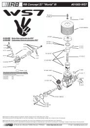
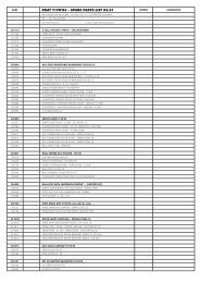
30 1100 CHASSIS 2.5 MM GRAPHITE - CNC MACHINED<br />
30 1160 UPPER DECK - 2.5 MM GRAPHITE - CNC MACHINED<br />
30 1200 NYLON BUMPER<br />
30 2010 ALU SUSPENSION BULKHEAD FRONT RIGHT - HARD COATED<br />
30 2020 ALU SUSPENSION BULKHEAD FRONT LEFT - HARD COATED<br />
30 3010 ALU SUSPENSION BULKHEAD REAR RIGHT - HARD COATED<br />
30 3020 ALU SUSPENSION BULKHEAD REAR LEFT - HARD COATED<br />
30 9030 BALL-BEARING MR95ZZ 5x9x3 (2)<br />
30 9040 BALL-BEARING MR106ZZ 6x10x3 (2)<br />
In line with our policy of continuous product development, the exact specifications of the kit may vary. In the unlikely event<br />
of any problems with your new kit, you should contact the model shop were you purchased it, quoting the part number.<br />
We do reserve all rights to change any specification without prior notice. All rights reserved.<br />
The <strong>T1</strong> chassis comes partially preassembled out of the box. Before starting assembly, please disassemble the chassis parts, and keep them,<br />
including the screw hardware, close at hand. In the assembly steps that follow, each section begins with a list of parts. Any parts indicated with<br />
color A come from previously disassembled chassis parts.<br />
1
1.FRONT & REAR DIFFERENTIAL<br />
FRONT & REAR DIFFERENTIAL<br />
305050<br />
305020<br />
309020<br />
305082<br />
305090<br />
305050<br />
305082<br />
C8<br />
ST 3x8<br />
309070<br />
305010<br />
305040<br />
305050<br />
BB 5x8<br />
1. Hold the diff shaft with the installed pulley facing up. Place the other 5x8<br />
ball-bearing on the center stub on top of the other bearing.<br />
2. The 17x23 diff washer has a front side (brightly polished) and a back side<br />
(ground, dull finish). The polished side will go against the diff balls and the<br />
ground side will go against the diff shaft. Put a very thin coat of grease on the<br />
back side of a diff washer, and place it on the long diff shaft. The washer<br />
should seat centered on the diff shaft, and the layer of grease will hold it in<br />
place.<br />
3. Insert the diff screw into the long diff shaft and place a small Allen wrench<br />
through both pieces where the hole lines up. The end of the diff screw should<br />
extend about 8mm from the center of the diff shaft.<br />
4. Lower the long diff shaft with the screw pointing down onto the short shaft<br />
with the pulley. Carefully thread the diff screw into the center of the short diff<br />
shaft. Keep tightening until the diff washer just touches the diff balls.<br />
➊<br />
➍<br />
➋<br />
➌<br />
➌<br />
Place another wrench in the slot of the short diff shaft.<br />
BAG<br />
01<br />
30 5010 ALU DIFF LONG OUTPUT SHAFT HARD COATED<br />
30 5020 ALU DIFF SHORT OUTPUT SHAFT HARD COATED<br />
30 5040 SCREW FOR EXTERNAL DIFF ADJUSTMENT - SPRING STEEL<br />
30 5050 DIFF PULLEY 34T WITH LABYRINTH DUST COVERS<br />
30 5082 DIFF WASHER 17x23x1 (2)<br />
30 5090 BALL STEEL 2.4 MM (24)<br />
30 9020 BALL-BEARING MR85ZZ 5x8x2.5 (2)<br />
30 9070 BALL-BEARING AXIAL F3-8 3x8x3.5<br />
Please note that properly functioning differentials are extremely important to the performance of the car. Therefore, it is imperative that you make<br />
sure that the differentials move freely after assembly or rebuilding, and after every run. For differential adjustment, please refer to the Set-up Book.<br />
C 8<br />
ST 3x8<br />
BA 3x8<br />
The long diff output shaft is preassembled at the factory. When it<br />
comes time to clean or rebuild the diff, please follow these steps:<br />
1. Insert the smaller of the two thrust washers into the long diff shaft<br />
as shown in the diagram above.<br />
2. Apply a little grease to the balls in the caged thrust ball holder.<br />
Coat each side with grease. Insert the thrust ball cage into the long<br />
diff shaft.<br />
3. Place the larger thrust washer in the diff shaft.<br />
4. Insert the four cone washers according to the detail shown above.<br />
5. Secure the assembly with the C8 clip. There is a groove inside the<br />
diff shaft for the clip to seat into.<br />
Note: Assembly will be easier with snap-ring pliers.<br />
➎<br />
➍<br />
FACTORY PREASSEMBLED<br />
8.0 mm<br />
3.2 mm<br />
➌<br />
➋<br />
7.8 mm<br />
3.0 mm<br />
➊<br />
GREASE<br />
Tighten the diff until you feel some resistance. To<br />
check the diff, hold both wrenches in one hand and<br />
try to move the pulley with the other. It should take<br />
some force to get the pulley to slip between the two<br />
outdrives. Then remove both wrenches and rotate<br />
one of the diff halves while holding the pulley<br />
stationery. The action should feel smooth. If it<br />
doesn't, loosen the diff screw 1/16 to 1/8 of a turn.<br />
Final adjustment will be made with the diff in the car<br />
and on the track.<br />
Cover each of the diff halves with the Labyrinth Dust Covers. The<br />
covers fit precisely and should "snap" into place. Once snapped on,<br />
the covers will seat perfectly.<br />
BB 5x8<br />
1. The diff locknut is pre-installed in the short diff output shaft. If you<br />
need to replace the diff locknut, push it out from the opposite side<br />
with the tip of a wrench. Insert a new one into the short diff shaft.<br />
2. Place one 5x8 ball-bearing on the short center stub of the diff<br />
shaft.<br />
3. Each of the 17x23 diff washers has a front side (brightly polished)<br />
and a back side (ground, dull finish). The polished side will go<br />
against the diff balls and the ground side will go against the diff<br />
shaft. Put a very thin coat of grease on the back side of a diff washer,<br />
and place it on the diff shaft. The washer should seat centered on the<br />
diff shaft, and the layer of grease will hold it in place.<br />
4. Press the diff pulley onto the ball bearing.<br />
➊<br />
FACTORY PREASSEMBLED<br />
➋<br />
➌<br />
➍<br />
When you need to open the differential, use the shaft of a wrench to<br />
spread the dust covers apart to pop them off.<br />
Repeat all the steps to build a second differential.<br />
B 2.4<br />
1. Apply a little bit of grease into each of the 12 holes in the diff pulley.<br />
2. Place the 12 balls in the diff pulley holes.<br />
➋<br />
GREASE<br />
Please note the way that the<br />
cone washers need to face<br />
each other.<br />
Cutaway view of the ball<br />
differential.<br />
➊<br />
2<br />
3
2. REAR TRANSMISSION<br />
REAR TRANSMISSION<br />
305510<br />
PIN 2x10<br />
305510<br />
305580<br />
305570<br />
303010<br />
309050<br />
302040<br />
305000<br />
305440<br />
303040<br />
302053<br />
309030<br />
302040<br />
SH M3x10<br />
302040<br />
309040<br />
ST6x12<br />
305540<br />
302040<br />
5. Press the 2x10 pin into the hole on the layshaft. Note that the pin should<br />
stick out from both sides equally.<br />
6. Install the 16T fixed pulley with the pin keyed into it. The fixed pulley and<br />
fixed pulley shim should be flush against the one-way pulley and the pin<br />
should not be visible.<br />
7. Install the two cone washers ST6x12 making sure they are facing the<br />
right way. Check the detail for the correct orientation.<br />
8. Install the one-way adjustment nut M6. Thread the nut on the layshaft<br />
very carefully so it installs true onto the threads. If it installs crooked, back it<br />
off the thread until you feel the end of the thread "click", then start threading<br />
forward again until it is straight. There should be some resistance to the nut;<br />
if the movement is too loose, use a little threadlock compound to give the<br />
nut some resistance. Note: If the one-way adjustment nut does not tighten<br />
flat against the fixed pulley, irregular wear to the pulleys may occur.<br />
Cutaway view of the main layshaft. Please note the correct<br />
orientation of the cone washers.<br />
305430<br />
SP M3x6<br />
301100<br />
303020<br />
SP M3x6<br />
SH M3x10<br />
1. Mount the right bulkhead to the lower chassis using M3x6 screws<br />
from the bottom.<br />
2. Insert the aluminum lower suspension holders into the plastic lower<br />
suspension hubs.<br />
3. Mount the plastic lower suspension hubs onto the bulkheads.<br />
Please note that the rear lower suspension hub has a hole all the way<br />
through and the forward one has a hole that doesn't go through all<br />
the way.<br />
4. Use M3x10 screws to mount the aluminum lower suspension<br />
holders and plastic lower suspension hubs. Make sure that the holes<br />
for the pivot pins are at the bottom, just above the lower chassis. Do<br />
not tighten the screws all the way; final tightening will be done after<br />
installing the lower arms.<br />
➊<br />
➍<br />
DETAIL<br />
➌<br />
➋<br />
BAG<br />
02<br />
30 2040 LOWER SUSPENSION HOLDER (SET 2+1+1)<br />
30 2053 ALU LOWER SUSPENSION HOLDER<br />
30 3040 ALU REAR BULKHEAD BRACE<br />
30 5430 KEVLAR REINFORCED DRIVE BELT FRONT 3 x 507 MM<br />
30 5440 KEVLAR REINFORCED DRIVE BELT REAR 4 x180 MM<br />
30 1100 CHASSIS 2.5 MM GRAPHITE - CNC MACHINED<br />
30 3010 ALU SUSPENSION BULKHEAD REAR RIGHT - HARD COATED<br />
30 3020 ALU SUSPENSION BULKHEAD REAR LEFT - HARD COATED<br />
30 9030 BALL-BEARING MR95ZZ 5x9x3 (2)<br />
30 9040 BALL-BEARING MR106ZZ 6x10x3 (2)<br />
30 5510 LAYSHAFT SPRING STEEL WITH NTEGRATED SPUR GEAR ADAPTER<br />
30 5540 ONE-WAY ADJUSTMENT NUT M6<br />
30 5570 FIXED PULLEY 16T<br />
30 5580 ONE WAY PULLEY 16T<br />
30 9050 BALL-BEARING 6700ZZ 10x15x4 (2)<br />
30 5000 BALL DIFFERENTIAL WITH LABYRINTH DUST COVERS - SET<br />
1. Place the front drive belt on the one-way pulley.<br />
2. Place the rear belt onto the assembled differential.<br />
3. Insert the longer output shaft of the differential into the<br />
ball-bearing pressed in the right side bulkhead, then place<br />
the drive belt onto the fixed pulley on the layshaft.<br />
➌<br />
BB 10x15<br />
P 2x10<br />
ST 6x12<br />
The bulkheads feature preinstalled layshaft bearings 6x10 and 5x9.<br />
Examine the two 10x15 ball-bearings. If they don't turn freely and easily, clean them until<br />
they do, then lubricate with light bearing oil.<br />
The ball-bearings go into the polished bearing hubs that are pressed into the bulkheads.<br />
The bearings are made to fit precisely and snugly, so use this method to install them:<br />
Place the bearing flat on a table. Then place the bulkhead over the bearing, with the<br />
bearing hub centered on the bearing. Once they are aligned, carefully press the<br />
bulkhead onto the bearing, taking great care to do it evenly. After<br />
installation, be sure that the ball-bearing turns freely and easily.<br />
Repeat with the other bearing and bulkhead.<br />
1. Insert the layshaft with spur gear adapter through the preinstalled ball-bearing<br />
in the bulkhead.<br />
➊<br />
2. Install the diff washer thrust shim.<br />
3. Install the 16T one-way pulley. Make sure that the one-way pulley "free wheels"<br />
when rotated forward, but locks onto the layshaft when rotated backward. (When<br />
looking at the layshaft head-on with the spur adapter away from you, the pulley's<br />
forward rotation is counter-clockwise.)<br />
4. Install the fixed pulley shim.<br />
➎<br />
➋<br />
➌<br />
➍<br />
SP M3x6<br />
SH M3x10<br />
1. Place the plastic lower suspension hubs<br />
onto the aluminum lower suspension holders<br />
that are already mounted onto the bulkheads.<br />
Remember that the rear hub is the one has a<br />
hole that goes all the way through,and be<br />
sure to check the orientation of the holes.<br />
2. Insert the bulkhead onto the differential<br />
and the layshaft. The layshaft needs to fit into<br />
the preinstalled ball-bearing in the bulkhead.<br />
3. Mount the left bulkhead to the lower<br />
chassis using M3x6 screws from the bottom.<br />
4. Mount the rear lower holders using M3x10<br />
screws. Do not fully tighten them; final<br />
tightening will be done after installing the<br />
lower arms.<br />
5. Mount the aluminum rear bulkhead brace<br />
with M3x10 screws onto the bulkheads from<br />
both sides. Do not fully tighten it; final<br />
tightening will be done after installing the<br />
lower arms.<br />
➎<br />
DETAIL<br />
➌<br />
➊<br />
➎<br />
➋<br />
➊<br />
➋<br />
➎<br />
➍<br />
➏ ➐ ➑<br />
4<br />
5
3. REAR SUSPENSION<br />
REAR SUSPENSION<br />
SB M3x4<br />
307310<br />
302080<br />
SB M4x8<br />
303110<br />
C10<br />
SB M3x10<br />
SB M3x6<br />
1. Release the pivot pin set screw to allow the arm to slide forward and back so that the<br />
wheelbase clips can be installed on the pivot pin.<br />
2. Install the clips for wheelbase adjustment. Use only three clips (one each of 4mm,<br />
3mm, and 2mm) on each arm. The initial setting is to install two clips (3 mm and 2 mm)<br />
in front of the arm and a 4 mm clip behind the arm. For adjustment, refer to the Set-up<br />
book.<br />
Note: If you find that the arm does not move freely after installing the clips, remove the<br />
4mm clip and lightly sand one side. Place the sand paper flat on a table and rub<br />
the clip on it in circles a few times. Repeat this until the arm moves freely with all three<br />
clips installed.<br />
3. Secure the pivot pins very lightly in the lower arms with the set screws. Be careful<br />
not to overtighten them.<br />
303200<br />
303230<br />
SB M3x4<br />
303240<br />
309050<br />
303310<br />
307350<br />
307354<br />
307352<br />
305230<br />
P 2x10<br />
P 2x10<br />
Now check the arms again for free movement.<br />
1. Lightly grease a coupling and insert it into the drive shaft joint.<br />
2. Slide the drive shaft joint into the wheel axle, aligning the cross<br />
holes.<br />
3. Insert the cross pin, making sure it is evenly spaced on both sides of<br />
the wheel axle.<br />
4. Install the plastic cap onto the pressed drive shaft pin. First insert<br />
one pin into a hole, then stretch the other hole on the plastic cap over<br />
the other pin.<br />
➍<br />
➋<br />
➊<br />
➌<br />
305240<br />
305320<br />
Repeat for both axles.<br />
305310<br />
BAG<br />
03<br />
30 2080 CASTER CLIPS SET - 4,3,2,1 MM (2)<br />
30 3110 SUSPENSION ARM REAR LOWER<br />
30 3200 ADJ. REAR TURNBUCKLE L/R 25 MM - SPRING STEEL (2+4)<br />
30 3230 ADJUSTABLE 5.8 MM BALL END - SPRING STEEL (2)<br />
30 3240 BALL UNIVERSAL 5.8 MM HEX (4)<br />
30 3310 UPRIGHT REAR<br />
30 5230 DRIVE SHAFT COUPLING - SPRING STEEL (2)<br />
30 5240 DRIVE SHAFT REPLACEMENT PLASTIC CAP 3 MM (4)<br />
30 5310 WHEEL AXLE REAR - INTEGRATED HEX HUB - HARD COATED (2)<br />
30 5320 DRIVE SHAFT REAR - SPRING STEEL (2)<br />
30 7310 REAR WISHBONE PIVOT PIN BOTTOM - SPRING STEEL (2)<br />
30 7350 6.8 MM BALL END WITH THREAD - SPRING STEEL (2)<br />
30 7352 ALU ADJUSTING NUT M8 x 1 (4)<br />
30 7354 PLASTIC BALL CUP 6.9 MM (4)<br />
30 9050 BALL-BEARING 6700ZZ 10x15x4 (2)<br />
SH M3x6<br />
Remove any flash (excess plastic) from the holes in the uprights before continuing.<br />
1. Thread a pivot ball into each of the pivot holes in the rear uprights.<br />
2. Place the plastic ball cups on top of the pivot balls. The concave (scooped) side goes<br />
against the pivot balls.<br />
3. Apply some grease to the threads of the aluminum adjustment plugs. Thread the plugs<br />
into the tapped holes to cover the pivot balls and ball cups. Adjust the plugs so that the<br />
pivot balls have the least amount of play while still allowing free movement in the<br />
uprights.<br />
4. Place an M3x6 screw through one of the upper holes on the upright into a steel pivot<br />
ball. Tighten the screw into the ball until you feel a "snap".<br />
Repeat for both sides, but in step 4., the screw should go through the opposite side of the<br />
upright.<br />
➍<br />
➍<br />
➊<br />
➋<br />
➌<br />
SB M4x8<br />
SB M3x4<br />
SB M3x10<br />
The left and right arms are identical, but mirrored.<br />
1. Thread a downstop adjustment screw M4x8 into the rear lower arm.<br />
It must stick out as indicated in the picture. This screw needs to be<br />
accessible from the top of the arm.<br />
2. Thread a pivot pin set screw M3x4 into the arm. Thread it just<br />
enough so it will stay in the hole; don't let it thread into the pivot pin<br />
area.<br />
3. Thread a shock mounting screw M3x10 into the hole located on the<br />
outside of the arm. The screw needs to stick out 3mm from the arm.<br />
➋<br />
➊<br />
➌<br />
3.0 mm<br />
1.7 mm<br />
10x15<br />
Clean and lubricate both 10x15 ball-bearings with light bearing oil.<br />
1. Slide a 10x15 ball-bearing onto the axle.<br />
2. Insert the drive shaft through the upright until the bearing on the axle is seated.<br />
Note the direction of installation from the diagram.<br />
3. Slide another 10x15 bearing over the drive shaft. Press the bearing into the<br />
upright, making sure that it fits precisely.<br />
➌<br />
➊<br />
➋<br />
1. Position the rear suspension arm in the rear bulkhead. It should seat between the two plastic lower<br />
suspension holders. Note that the pivot pin set screws should be seen from underneath the chassis.<br />
2. Align the holes in the arms with the suspension holders and slide<br />
a rear pivot pin through the hole to secure them. The flat spot on the<br />
pivot pin must be towards the rear and facing the bottom of the car.<br />
3. Tighten the M3x4 pivot pin set screw just until it touches the pivot pin.<br />
4. Once both pivot pins are installed, tighten all the screws that<br />
were left loose in section 02 Rear Transmission:<br />
-- Bulkhead brace M3x10 screws<br />
-- Lower chassis M3x6 screws<br />
-- Lower suspension holders<br />
After all the screws are tight, check the arms for free movement.<br />
➊<br />
➋<br />
C 10<br />
Fasten the axle to the upright by installing a snap ring in<br />
the groove on the axle by the drive shaft joint. To make it<br />
easier, place the hex portion of the axle flat on a table. Put<br />
one end of the snap ring into the groove on the opposite<br />
side of the axle cutout, and use a slotted screwdriver to<br />
work the rest of the clip in place.<br />
Repeat for the other axle and upright.<br />
To remove the snap ring, insert a small<br />
screwdriver in the axle cutout and pry it off,<br />
taking care not to let it fly off the workbench.<br />
6<br />
7
REAR SUSPENSION<br />
Assemble the rear turnbuckles by threading a ball joint onto each end of the spring steel turnbuckle.<br />
Note: The turnbuckle has a CCW thread on one end and a CW thread on the other end.<br />
Adjust the turnbuckles to a length of 51.5 mm, measured end-to-end.<br />
51.5 mm<br />
4. FRONT TRANSMISSION<br />
309010<br />
302500<br />
305430<br />
302040<br />
SB M3x4<br />
1. Insert an adjustable 5.8 mm ball end into the hole on the bulkhead with<br />
the flat side facing up.<br />
2. Secure the ball end using an M3x4 set screw in the threaded hole above<br />
where the ball end is installed.<br />
➋<br />
C 6,5<br />
302032<br />
302040<br />
Install one in both the left and right bulkhead parts.<br />
8.0 mm<br />
➊<br />
SB M3x4<br />
O 5x1<br />
302053<br />
305000<br />
309050<br />
302040<br />
302020<br />
302060<br />
302010<br />
SP 3x6<br />
SH M3x10<br />
Start mounting the rear upgrights by screwing the two pivot balls into the arm just enough<br />
so they are secured by a few threads. The holes in the arm are pre-tapped for easy<br />
installation. Turn each pivot ball only 1-2 turns at a time.<br />
Position the plastic end of the drive shaft in the differential outdrive slot.<br />
Now continue screwing in he pivot balls.<br />
Adjust the pivot balls until there is a 2.5 mm gap between the upright and the end of the<br />
suspension arm, as shown in the detail illustration.<br />
2.5 mm<br />
2.5 mm<br />
BAG<br />
04<br />
BB 10x15<br />
C 6.5<br />
O 5x1<br />
SB M3x4<br />
30 2032 ALU NUT (2)<br />
30 2040 LOWER SUSPENSION HOLDER (SET 2+1+1)<br />
30 2053 ALU LOWER SUSP. HOLDER<br />
30 2060 FRONT UPPER SUSPENSION HOLDER (SET 4+8)<br />
30 2010 ALU SUSPENSION BULKHEAD FRONT RIGHT HARD COATED<br />
30 2020 ALU SUSPENSION BULKHEAD FRONT LEFT HARD COATED<br />
1. Examine the two 10x15 ball-bearings. If they don't turn freely and<br />
easily, clean them until they do, then lubricate with light bearing oil. As in<br />
the rear, the ball-bearings go into the polished bearing hubs that are<br />
pressed into the bulkheads. Use the same method used to install the<br />
10x15 bearings in the rear bulkhead. After installation, be sure that the<br />
ball-bearing turns freely and easily. Repeat with the other bearing and<br />
bulkhead.<br />
2. Put a 5x1 rubber O-ring on each of the 4 front upper suspension<br />
holders.<br />
3. Insert the front upper suspension holders into the bulkheads.<br />
4. Fasten the upper suspension holders from the inside of the bulkhead<br />
with C 6.5 clips.<br />
5. Insert an M3x4 set screw into each of the 2 rear upper suspension<br />
holders.<br />
➎<br />
30 2500 CENTRAL SERVO SAVER (SET)<br />
30 9010 BALL-BEARING MR74ZZ 4x7x2.5 (2)<br />
30 9050 BALL-BEARING 6700ZZ 10x15x4 (2)<br />
30 5000 BALL DIFFERENTIAL WITH LABYRINTH DUST COVERS - SET<br />
➌<br />
➋<br />
➍<br />
➊<br />
Connect the adjustable turnbuckles to the balls on the rear uprights and the<br />
adjustable ball end.<br />
The eyelets must be snapped onto the balls. The suspension arms must be able to<br />
fall freely when lifted up, then dropped. If there is any binding in an eyelet that<br />
prevents the arm from falling freely, remove it from the ball and lightly squeeze it<br />
with a pair of pliers. Remount it and check the arm again. Repeat this process until<br />
the eyelet has no more binding.<br />
SH M3x10<br />
SP M3x6<br />
BB 4x7<br />
1. Install the servo saver plastic cover in the 9mm hole on the chassis. See the illustration for the<br />
proper location.<br />
2. Insert a 4x7 ball-bearing into the plastic cover.<br />
3. Insert an aluminum nut into both plastic closed lower suspension holders.<br />
4. Insert the aluminum lower suspension holder into the plastic open suspension holder and mount<br />
them to the right bulkhead using an M3x10 screw. Make sure that the holes for the pivot pins are<br />
at the bottom, just above the lower chassis.<br />
5. Mount both plastic closed suspension holders to both bulkheads using M3x10 screws. Again,<br />
make sure that the holes for the pivot pins are at the bottom. Do not tighten the screws all the way;<br />
final tightening will be done after installing the lower arms.<br />
6. Mount the right side bulkhead to the chassis using M3x6 screws.<br />
➏<br />
➋<br />
➊<br />
➎ ➌<br />
➍<br />
DETAIL<br />
The rear suspension is complete. Once again, make sure that the<br />
whole assembly moves freely and easily.<br />
SP M3x6<br />
SH M3x10<br />
1. Put the front drive belt on the second differential.<br />
2. Insert the short diff shaft of the differential into the bearing pressed into the right bulkhead.<br />
3. Install the remaining open suspension holder onto the aluminum lower suspension holder.<br />
4. Place the left side bulkhead onto the chassis. The diff needs to seat into the bearing pressed<br />
into the bulkhead.<br />
5. Use M3x6 screws to fasten the left side bulkhead to the chassis.<br />
6. Fasten the lower suspension holder assembly to the left side bulkhead with an M3x10 screw.<br />
➊<br />
➏<br />
➋ ➌ ➍<br />
➎<br />
8<br />
9
5. FRONT SUSPENSION<br />
FRONT SUSPENSION<br />
302080<br />
302140<br />
302220<br />
BB 10x15<br />
C 10<br />
Clean and lubricate both 10x15 ball-bearings with light bearing oil.<br />
1. Slide a 10x15 ball-bearing onto the axle.<br />
2. Insert the drive shaft through the steering block until the bearing on the axle is<br />
seated. Note the direction of installation from the diagram.<br />
3. Slide another 10x15 bearing over the drive shaft. Press the bearing into the steering<br />
block, making sure that it fits precisely.<br />
4. Fasten the axle to the steering block by installing a snap ring in the groove on the<br />
axle by the drive shaft joint. To make it easier, place the hex portion of the axle flat on<br />
a table. Put one end of the snap ring into the groove on the opposite side of the axle<br />
cutout, and use a slotted screwdriver to work the rest of the clip in place.<br />
Repeat for the other axle and steering block.<br />
➋<br />
➊<br />
➌ ➍<br />
C10<br />
302650<br />
307250<br />
305240<br />
SB M4x8<br />
302130<br />
307230<br />
307210<br />
SB M4x8<br />
SB M3x10<br />
SB M3x4<br />
1. Thread a downstop adjustment screw M4x8 into the front lower<br />
arm. The left and right arms are identical, but mirrored, so be sure to<br />
check the orientation.<br />
2. Thread a shock mounting screw M3x10 into the hole located on the<br />
outside of the arm. Check the illustration for the proper hole. The<br />
screw needs to stick out 3mm from the arm.<br />
3. Thread a pivot pin set screw M3x4 into the arm from the bottom.<br />
Thread it just enough so it will stay in the hole; don't let it thread into<br />
the pivot pin area.<br />
➊<br />
➌<br />
➋<br />
3.0 mm<br />
1.0 mm<br />
305230<br />
305220<br />
307254<br />
307252<br />
P 2x10<br />
305210<br />
302110<br />
SB M3x10<br />
SB M3x4<br />
309050<br />
302210<br />
1. Position the lower front suspension arm in the front bulkhead. It should seat<br />
between the two plastic lower suspension holders. Note that the pivot pin set screws<br />
should be accessible from the 9mm holes underneath the chassis.<br />
2. Align the holes in the arms with the suspension holders and slide a lower front<br />
pivot pin through the hole to secure them. The flat spot on the pivot pin must be<br />
towards the rear and facing the bottom of the car.<br />
3. Tighten the M3x4 pivot pin set screw just until it touches the pivot pin.<br />
4. Once both pivot pins are installed, tighten all the screws that were left loose in<br />
section 04 Front Transmission:<br />
-- Lower chassis M3x6 screws<br />
-- Lower suspension holders<br />
After all the screws are tight, check the arms for free movement.<br />
➊<br />
➋<br />
BAG<br />
05<br />
30 2080 CASTER CLIPS SET - 4+3+2+1 MM (2)<br />
30 2110 SUSPENSION ARM FRONT LOWER<br />
30 2130 SUSPENSION ARM FRONT UPPER RIGHT<br />
30 2140 SUSPENSION ARM FRONT UPPER LEFT<br />
30 2210 STEERING BLOCK RIGHT<br />
30 2220 STEERING BLOCK LEFT<br />
30 2650 5 MM BALL END, WITH THREAD (6)<br />
30 5210 WHEEL AXLE FRONT - INTEGRATED HEX HUB - HARD COATED (2)<br />
30 5220 DRIVE SHAFT FRONT (2)<br />
30 5230 DRIVE SHAFT COUPLING - SPRING STEEL (2)<br />
30 5240 DRIVE SHAFT REPLACEMENT PLASTIC CAP 3 MM (4)<br />
30 7210 FRONT WISHBONE PIVOT PIN BOTTOM - SPRING STEEL (2)<br />
30 7230 FRONT WISHBONE PIVOT PIN UPPER - SPRING STEEL (2)<br />
30 7250 PIVOT BALL 8.5 MM - SPRING STEEL (2)<br />
30 7252 ALU ADJUSTING NUTS M10x1 (4)<br />
30 7254 PLASTIC BALL CUP 8.4 MM (4)<br />
30 9050 BALL-BEARING 6700ZZ 10x15x4 (2)<br />
1. Position the upper front suspension arms in the upper suspension holders.<br />
2. Slide an front upper pivot pin through the holders and the arm with the flat spots<br />
facing the side of the car.<br />
3. Tighten the M3x4 pivot pin set screws just until they touch the pivot pins.<br />
4. Install the caster clips. Use only 3 mm, 2 mm and 1 mm clips. Apply 2 mm clip in<br />
front of each arm and 1 mm + 3 mm clip behind each arm. For advanced set-up,<br />
refer to the Set-up Book.<br />
➌<br />
➍<br />
P 2x10<br />
1. Lightly grease a coupling and insert it into the drive shaft joint.<br />
2. Slide the drive shaft joint into the wheel axle, aligning the cross holes.<br />
3. Insert the cross pin, making sure it is evenly spaced on both sides of the wheel axle.<br />
4. Install the plastic cap onto the pressed drive shaft pin. First insert one pin into a hole,<br />
then stretch the other hole on the plastic cap over the other pin.<br />
Repeat for both axles.<br />
1. Insert a pivot ball into each of the pivot holes in the steering blocks.<br />
2. Place the plastic ball cups on top of the pivot balls. The concave (scooped) side goes<br />
against the pivot balls.<br />
3. Apply some grease to the threads of the aluminum adjustment plugs. Thread the plugs<br />
into the tapped holes to cover the pivot balls and ball cups. Adjust the plugs so that the<br />
pivot balls have the least amount of play while still allowing free movement in the steering<br />
blocks.<br />
4. Mount a 5mm small ball end to the top of each steering arm.<br />
➌<br />
➋<br />
➊<br />
➌<br />
➍<br />
➊<br />
RIGHT<br />
➋<br />
➍<br />
LEFT<br />
Start mounting the steering blocks by screwing the two pivot balls into<br />
the arm just enough so they are secured by a few threads. The holes in<br />
the arm are pre-tapped for easy installation. Turn each pivot ball only<br />
1-2 turns at a time. Position the plastic end of the drive shaft in the<br />
differential outdrive slot. Now continue screwing in the pivot balls until<br />
there is a gap between the upper<br />
and lower portions of the steering<br />
block and the ends of the<br />
2.6mm<br />
suspension arms, as shown in the<br />
detail illustration.<br />
The front suspension is complete.<br />
Make sure that the whole assembly<br />
moves freely and easily.<br />
3.5mm<br />
➊<br />
➋<br />
10<br />
11
6. SERVO SAVER<br />
302580<br />
or<br />
302582<br />
302500<br />
309010<br />
C4<br />
Assemble the steering rods by threading a ball-joint onto each end of the spring steel steering rods.<br />
Note that the steering rod has a CCW thread on the long end and a CW thread on the short end.<br />
Also note that the ball-joints should be 180-degrees to each other.<br />
67 mm<br />
SERVO SAVER<br />
302500<br />
302600<br />
RIGHT<br />
302620<br />
302650<br />
1:1<br />
65 mm<br />
LEFT<br />
302500<br />
302500<br />
302500<br />
Assemble the servo link by threading a ball-joint onto both ends. Note that the rod<br />
has a CCW thread on one end and a CW thread on the other.<br />
Also note that the ball-joints should be perpendicular (90-degrees) to each other.<br />
FACTORY PREASSEMBLED<br />
1:1<br />
approx. 47 mm<br />
BAG<br />
06<br />
30 2500 CENTRAL SERVO SAVER (SET)<br />
30 2580 NYLON SERVO HORN - KO, JR, AIRTRONICS, MULTIPLEX<br />
30 2582 NYLON SERVO HORN - FUTABA, ROBE<br />
30 2600 ADJ. STEERING ROD L/R 40 MM - SPRING STEEL + BALL JOINT (2+4)<br />
301160 UPPER DECK - 2.5 MM GRAPHITE - CNC MACHINED<br />
30 2620 ADJ. STEERING ROD L/R 22 MM - SPRING STEEL + BALL JOINT (1+2)<br />
30 2650 5 MM BALL END, WITH THREAD (6)<br />
30 2660 BALL JOINT 5 MM (6)<br />
30 9010 BALL-BEARING MR74ZZ 4x7x2.5 (2)<br />
1. Using pliers, press the ball-joints of the steering rods onto the ball<br />
ends on the upper servo saver arm. Use the ball-joints on the longer<br />
end of the steering rods.<br />
2. Using pliers, press the ball-joint of the servo link onto the ball end<br />
on the lower servo saver arm.<br />
➋<br />
C 4<br />
The servo saver is partially preassembled from the factory and requires only a<br />
few steps to finish.<br />
If you need to assemble the parts yourself, perform the following steps:<br />
1. Place the servo saver spring on the steering post.<br />
2. Place the lower servo saver arm on the steering post.<br />
3. Place the upper servo saver arm on the steering post on top of the lower<br />
arm. Note that the upper and lower arms should interlock at a 90-degree<br />
angle. Check the illustration for proper orientation.<br />
4. Press the servo saver arm down and secure the servo saver with a C4 clip.<br />
The clip snaps into a groove on the steering post.<br />
➌<br />
➍<br />
➊<br />
➋<br />
1. Choose the proper servo horn for your servo. See the parts list<br />
above to match your servo manufacturer to the proper servo horn.<br />
2. Mount a ball end into the servo horn. Note that the thread will<br />
extend through the servo horn, but will not affect operation. If desired,<br />
you can file the exposed threads flat.<br />
3. Press the other ball-joint from the servo link onto the ball on the<br />
servo horn.<br />
➊<br />
➋<br />
➌<br />
➊<br />
1. Thread a 5mm small ball end into the lower servo saver. Be sure that the<br />
ball is on top.<br />
2. Thread two 5mm small ball ends up into the upper servo saver arm. The<br />
two balls should be on the bottom.<br />
➊<br />
BB 4x7<br />
1. Insert the plastic cap into the upper deck from underneath. See the<br />
illustration for proper orientation.<br />
2. Place the 4x7 ball-bearing in the plastic cap.<br />
➊<br />
➋<br />
➋<br />
12<br />
13
7. SHOCK ABSORBERS<br />
SHOCK ABSORBERS<br />
308050<br />
308080<br />
LONG<br />
REAR<br />
308010<br />
308040<br />
SHORT<br />
FRONT<br />
308094 ORANGE<br />
308095 WHITE<br />
308096 YELLOW<br />
O 3.1x1.6<br />
1. Lubricate a small O-ring with a couple of drops of shock oil. Taking<br />
care not to rip or damage the O-ring, place it over the extended end<br />
of the shock rod.<br />
2. Install the end-cap on the bottom of the shock body. Lock it in place<br />
by turning it about 1/8 of a turn CW.<br />
➊<br />
➋<br />
C2<br />
308010<br />
308010<br />
S3<br />
C3<br />
O 12<br />
308070<br />
Grip the top of the exposed thread of the shock rod with pliers and thread the ball-joint onto<br />
the shock rod.<br />
308250<br />
LONG REAR<br />
308150<br />
SHORT FRONT<br />
308010<br />
Hint: Pre-thread the ball-joint using an M3 screw. This will make it easier to thread the balljoint<br />
onto the shock rod.<br />
Hold here<br />
303240<br />
BAG<br />
07<br />
30 3240 BALL UNIVERSAL 5.8 MM HEX (4+4)<br />
30 8010 NYLON FRAME SHOCK PARTS 4-STEP<br />
30 8040 SHOCK ADJ. NUT ALU + O-RING<br />
30 8050 SHOCK CAP-NUT ALU<br />
30 8070 O-RING / SHIM<br />
30 8094 SPRING-SET D=1.4 ORANGE (2+2) (INCLUDED)<br />
30 8150 HARDENED PISTON RODS FRONT (2)<br />
30 8250 HARDENED PISTON RODS REAR (2)<br />
30 8095 SPRING-SET D=1.5 WHITE (2+2) (OPTION)<br />
30 8096 SPRING-SET D=1.6 YELLOW (2+2) (OPTION)<br />
30 8120 ALU SHOCK-BODY TEFLON FRONT (2) (OPTION)<br />
30 8220 ALU SHOCK-BODY TEFLON REAR (2) (OPTION)<br />
Shocks are one of the biggest factors in the proper performance of your car. These unique 4-step externally adjustable shocks must be assembled<br />
with extreme precision. After removing the nylon parts from the frame, make sure to remove any excess plastic flash with a sharp knife.<br />
Shock filling and bleeding sequence (perform for all four shocks):<br />
1. Fully extend the piston rod so that the piston is at the bottom of the<br />
shock body.<br />
2. Hold the shock upright and fill the shock body with oil.<br />
3. Let the oil settle and allow the air bubbles to rise to the top. Slowly<br />
move the piston up and down until no more air bubbles appear.<br />
4. Place the rubber bladder on top of the shock body. Some oil should<br />
spill out.<br />
➋<br />
➊<br />
➌<br />
➍<br />
Cut all shock parts free from the parts tree. The upper piston has a small hole in the center. The<br />
lower piston has a large hole in the center. Press the upper piston into the lower piston, carefully<br />
noting the orientation from the illustration.<br />
Place the top pivot-point on the bladder. Note the key notch on the top-pivot point.<br />
Place the aluminum collar over the top pivot-point, taking care to match the key notch on the collar and top-pivot point, and<br />
fully thread it on the shock body. More excess oil may escape.<br />
notch<br />
C 1.9<br />
C 2.3<br />
Perform for all four upper/lower piston assemblies and 4 shock rods:<br />
1. Install a C-clip 2.3 on the lower groove of the shock rod.<br />
2. Place an S 3 washer on the shock rod.<br />
3. Thread the upper/lower piston assembly onto the shock rod.<br />
4. Install a C-clip 1.9 on the upper groove of the shock rod.<br />
➍<br />
➌<br />
➊<br />
➋<br />
Check to make sure the shock absorber functions properly. The shock must move up and down freely with only "hydraulic"<br />
dampening. If any air is still in the shock, open it again and start the bleeding procedure over.<br />
Dampening adjustment:<br />
Fully extend the shock rod and turn it slightly to lock the piston in the shock body. Turning the shock rod fully CCW aligns 4<br />
holes in the pistons (softest dampening). Turning the shock rod fully CW aligns only one hole in the pistons (hardest). The<br />
shocks have 4 settings, each of which can be felt by a little "click". Set the front shocks to position 3 (3 holes open-- medium)<br />
and the rear shocks to position 4 (4 holes open -- lightest).<br />
S 3<br />
Match the shock rod assemblies with the proper shock bodies and insert the rods into the<br />
appropriate body:<br />
-- the long rods go with the long shock bodies (rear)<br />
-- the short rods go with the short shock bodies (front)<br />
Shock length adjustment:<br />
It is important that the two shocks on each end of the car (front or rear)<br />
are equal lengths. Adjust the length of the shock by tightening or<br />
loosening the ball-joint on the shock rod.<br />
Fully extended front shocks: 68.0 mm<br />
Fully extended rear shocks: 77.0 mm<br />
1. Install the springs on all four shocks. The short springs go on the<br />
short front shocks.<br />
2. Secure the spring with a spring cup.<br />
3. Use pliers to install a 5.8 mm ball universal into each upper and<br />
lower eyelet on the assembled shocks.<br />
➌<br />
O 12.1x16<br />
Perform for all four shock bodies:<br />
1. Insert an 12.1x16 O-ring inside the groove of a threaded shock<br />
adjustment collar.<br />
2. Thread the adjustment collar onto the shock body.<br />
Note: Apply a little shock oil to the O-rings to make installation onto<br />
the shock body easier.<br />
Cutaway view of assembled adjustment collar<br />
➊<br />
➋<br />
➋<br />
➊<br />
14<br />
15
8. REAR FINAL ASSEMBLY<br />
9. FRONT FINAL ASSEMBLY<br />
301320<br />
301330<br />
P 2x10<br />
303090<br />
302090<br />
SB M3x6<br />
308100<br />
301212<br />
SB M3x6<br />
SH M3x8<br />
301220<br />
SH M3x6<br />
308200<br />
SS 2,9X9.5<br />
SP M3x8<br />
N M3<br />
301200<br />
SS 2,9x13<br />
BAG<br />
08<br />
SH M3x6<br />
30 1330 REAR BODY MOUNT SET<br />
30 3090 SHOCK TOWER REAR - 2.5 MM GRAPHITE - CNC MACHINED<br />
30 8200 REAR SHOCK ABSORBER<br />
Mount the rear shock tower onto the rear bulkhead with M3x6 screws.<br />
BAG<br />
09<br />
SS 2.9x9.5<br />
SP M3x8<br />
N M3<br />
30 1320 FRONT BODY MOUNTS ( SET )<br />
30 1212 BUMPER UPPER HOLDER - 2.5 MM GRAPHITE<br />
CNC MACHINED<br />
30 1200 NYLON BUMPER<br />
30 1220 FOAM BUMPER<br />
N M3<br />
1. Mount the nylon bumper to the chassis.<br />
2. Place an M3 nut into the hex recess in the bumper.<br />
3. Thread an M3x8 screw up through the bottom of the chassis<br />
and through the bumper into the nut.<br />
4. Use two 2.9x9.5 self-tapping screws to finish securing the nylon<br />
bumper to the chassis.<br />
30 2090 SHOCK TOWER FRONT - 2.5 MM GRAPHITE<br />
CNC MACHINED<br />
30 8100 FRONT SHOCK ABSORBER<br />
➌<br />
➌<br />
➍<br />
➋<br />
➊<br />
SH M3x8<br />
P 2x10<br />
1. Glue the rubber washers onto the top of the plastic body<br />
post stops.<br />
2. Insert the body posts from the inner side of the shock tower<br />
so the bottom plastic pin keys into the bottom hole on the<br />
shock tower. Use an M3x8 screw to fasten each body post.<br />
3. Insert a 2x10 pin into one of the holes on the rear body<br />
post. Use the same hole position on both posts.<br />
4. Slide the body post stops down over the posts. The body<br />
stops should "click" onto the pin.<br />
➊<br />
➋<br />
➌<br />
SS 2.9x13<br />
P 2x10<br />
SH M3x6<br />
1. Insert the body posts down into the holes of the upper bumper<br />
holder.<br />
2. Slide the foam bumper up onto the body posts so the posts extend<br />
down through the foam bumper.<br />
3. Position the bumper assembly onto the nylon bumper.<br />
4. Secure the body posts to the nylon bumper from below using two<br />
2.9x13 self-tapping screws.<br />
5. Secure the graphite upper bumper holder to the bulkhead using two<br />
M3x6 screws.<br />
➎<br />
➍<br />
➌<br />
➊<br />
➋<br />
Mount the front shock tower to the front bulkhead with M3x6 screws.<br />
SH M3x6<br />
1. Mount the tops of the assembled rear shocks on the graphite<br />
shock tower using M3x6 screws. Use the middle of the three<br />
holes on the shock tower.<br />
2. Mount the lower ends of the shocks onto the exposed screw on<br />
the lower suspension arm. Refer to the Set-up Book to better<br />
understand the different mounting locations.<br />
SH M3x6<br />
➊<br />
➋<br />
SH M3x6<br />
1. Mount the tops of the assembled front shocks on the graphite shock<br />
tower using M3x6 screws. Use the middle of the three holes on the shock<br />
tower.<br />
2. Mount the lower ends of the shocks onto the exposed screw on the<br />
lower suspension arm. Refer to the Set-up Book to better understand the<br />
different mounting locations.<br />
➊<br />
➋<br />
16<br />
17
10. SERVO SAVER, BATTERY HOLDER & UPPER DECK ASSEMBLY<br />
11. ACCESSORY INSTALLATION<br />
SP M3x6<br />
306310<br />
301160<br />
306140<br />
306110<br />
SB M3x3<br />
305724<br />
306300<br />
SH M3x8<br />
SERVO<br />
306150<br />
S 3.2<br />
306200<br />
SS 2.9x10<br />
SH M3x8<br />
SP M3 x 6<br />
305793<br />
305790 OPTION<br />
SP M3x6<br />
BAG<br />
10<br />
30 6110 BATTERY MOUNT STRAP - 2.5 GRAPHITE FOR 3 BATT. - (SET 2)<br />
30 6140 BATTERY HOLDER MOUNT WITH BALL END (2)<br />
30 6150 BATTERY HOLDER MOUNT WITH THREAD (2)<br />
SP M3x6<br />
30 1160 UPPER DECK - 2.5 MM GRAPHITE - CNC MACHINED<br />
✸ CENTRAL SERVO SAVER + STEERING RODS<br />
SH M4x8<br />
SH M3x5<br />
305940<br />
ST 4x12<br />
1. Work the steering rods through the front bulkheads and place the<br />
assembled servo saver on the chassis. It must seat into the ball bearing<br />
in the plastic cup on the lower chassis.<br />
2. Use pliers to press the ball-joints onto the ball ends of each steering<br />
arm.<br />
BAG<br />
11<br />
30 5724 PINION GEAR ALU HARD COATED 24T / 48 (INCLUDED)<br />
30 5793 SPUR GEAR 93T/48 (INCLUDED)<br />
30 5940 24 MM WHEELS (4)<br />
30 5940 26 MM WHEELS (2) (OPTION)<br />
30 6200 ALU SERVO MOUNT (2)<br />
30 6300 ANTENNA MOUNT<br />
30 6310 ANTENNA (2)<br />
30 5621 PINION GEAR STEEL 21T / 48 (OPTION)<br />
30 5622 PINION GEAR STEEL 22T / 48 (OPTION)<br />
30 5623 PINION GEAR STEEL 23T / 48 (OPTION)<br />
30 5624 PINION GEAR STEEL 24T / 48 (OPTION)<br />
30 5625 PINION GEAR STEEL 25T / 48 (OPTION)<br />
30 5626 PINION GEAR STEEL 26T / 48 (OPTION)<br />
30 5627 PINION GEAR STEEL 27T / 48 (OPTION)<br />
30 5628 PINION GEAR STEEL 28T / 48 (OPTION)<br />
30 5725 PINION GEAR ALU HARD COATED 25T / 48 (OPTION)<br />
30 5726 PINION GEAR ALU HARD COATED 26T / 48 (OPTION)<br />
30 5727 PINION GEAR ALU HARD COATED 27T / 48 (OPTION)<br />
30 5728 PINION GEAR ALU HARD COATED 28T / 48 (OPTION)<br />
30 5790 SPUR GEAR 90T / 48 (OPTION)<br />
SP M3x6<br />
1. Place the graphite upper deck on top of the bulkheads. The 4x7<br />
ball-bearing pressed into the plastic cover needs to seat onto the<br />
steering post of the servo saver assembly. Be sure that the servo saver<br />
can move freely and easily.<br />
2. Use four M3x6 screws to fasten the upper deck to the front and rear<br />
bulkheads. Note that the heads of the screws will protrude slightly from<br />
the upper deck. This is to make the chassis structure stiffer by locking<br />
the upper deck in place more securely.<br />
➊<br />
➋<br />
SH M3x5<br />
SH M3x8<br />
S 3.2<br />
1. Use M3x5 screws to mount the spur gear on the layshaft.<br />
2. Install a pinion gear on the motor shaft and secure it with set screw<br />
M3x3 that comes with the pinion.<br />
3. Put one 3.2mm washer each on two M3x8 screws. Use these to<br />
mount the motor to the right rear bulkhead.<br />
4. Adjust the motor and the pinion so that the pinion meshes with the<br />
spur gear. There should be just a tiny amount of play between the<br />
pinion teeth and the spur teeth.<br />
➋<br />
➌<br />
SB M3x3<br />
➊<br />
SP M3x6<br />
1. Stick the foam battery cushions on the underside of each battery<br />
strap.<br />
2. Press a plastic ball end hub into the large hole of each battery<br />
strap.<br />
3. Install the battery holder mount's ball end into the plastic hub. They<br />
will snap in place. Once installed, the ball end should pivot in all<br />
directions freely.<br />
4. Secure the threaded battery holder mounts onto the chassis with<br />
M3x6 screws. Orient it so the battery will fit in the cutout.<br />
5. Secure the ball-ended battery holder mounts onto the chassis with<br />
M3x6 screws. Again, orient it so the battery will fit in the cutout.<br />
➌<br />
➋<br />
➎<br />
➊<br />
➍<br />
SP M3x6<br />
SH M3x8<br />
1. Fasten the aluminum servo mounts to the chassis using M3x6<br />
screws.<br />
Note that the forward servo mount is fixed, while the rear servo mount<br />
can go in one of two holes, based on the width of your servo.<br />
2. Secure the servo to the servo mounts using M3x8 screws. We<br />
recommend using the rubber grommets supplied with the servo.<br />
3. Connect the servo horn to the servo with a screw supplied with<br />
servo.<br />
Refer to Set-Up Book for more info on correctly setting steering<br />
linkage.<br />
➋<br />
➌<br />
➊<br />
18<br />
19
ACCESSORY INSTALLATION<br />
SS 2.9x9.5<br />
SH M4x8<br />
1. Mount the receiver and speed controller on the car using doublesided<br />
tape. For different receiver mounting possibilities, refer to the<br />
Set-up Book.<br />
2. Mount the antenna holder based on the position of the receiver<br />
using a 2.9x9.5 screw from underneath the chassis. Slide the wire<br />
through the antenna tube, then push the base of the tube firmly into<br />
the mounting hole.<br />
The wire should fit through the slot on the side of the antenna mount.<br />
1. Install a foam insert into each tire. Make sure the insert is centered in<br />
each tire.<br />
2. Slide the tire with foam insert onto wheel.<br />
3. Glue the tires to the wheels with super glue (CA glue) equally around<br />
each tire on both sides.<br />
Warning: Follow the adhesive manufacturer's instructions for proper use<br />
and safety. Wear eye and hand protection.<br />
Mount the wheels on the axle hex hubs. Fasten them using M4x8<br />
screws and ST 4x12 cone washers. Note the installation of the washer<br />
in the illustration.<br />
➊<br />
➋<br />
➋<br />
GLUE CA<br />
➊<br />
CAUTION:<br />
• This product is not suitable for children except under the direct supervision of<br />
an adult.<br />
• First-time builders should seek advice from people who have building<br />
experience in order to assemble the model correctly and to allow the model<br />
to reach its performance potential.<br />
• Assemble this kit only in places away from the reach of very small children.<br />
• Exercise care when using any hand tools and sharp instruments during<br />
construction.<br />
• Carefully read all manufacturers warnings and cautions for any parts used in<br />
the construction and use of your XRAY <strong>T1</strong>.<br />
• Take adequate safety precautions prior to operating this model. You are<br />
responsible for this model's assembly and safe operation! XRAY MODEL<br />
RACING CARS does not take responsibility for any injury, damage,<br />
or misuse of this product while assembling or operating it.<br />
• Take care when building; some parts may have sharp edges. Keep small<br />
parts out of reach of small children.<br />
• Do not put fingers or any objects inside rotating or moving parts!<br />
• Right after use, do NOT touch equipment on the model because they may<br />
generate high temperatures!<br />
• When learning to drive, go to an area that has no obstacles that can<br />
damage your car if you crash.<br />
• Always turn off the receiver/speed control or disconnect XRAY <strong>T1</strong>'s battery<br />
pack before turning transmitter off.<br />
• Disconnect the battery pack before storing.<br />
• Remove any sand, mud, dirt, grass or water before putting your model away.<br />
• Use a recommended charger for the batteries and follow the instructions<br />
correctly. Over charging or charging incorrectly using inferior chargers can<br />
cause the batteries pack to become dangerously hot.<br />
• Regularly check the charger unit for potential hazards such as damage to the<br />
cable, plug, casing or other defects. Ensure that any damage is rectified<br />
before using the charger again.<br />
• Do not allow the transmitter batteries to run flat so you don't lose control of<br />
the car.<br />
• Do not allow any metal part to short circuit the batteries or speed control.<br />
• Be sure that your operating frequency is clear before running and never<br />
share the same frequency with somebody else at the same time!<br />
• When the model is behaving strangely immediately stop the model and<br />
check and clear the problem.<br />
• Do not stall the motor. The speed control will fail within seconds if power is<br />
applied to the motor when the car can not move.<br />
• Do not use your model:<br />
- near real cars, animals, or people that are unaware<br />
that an R/C car is being driven.<br />
- in places where children and people gather.<br />
- in residential districts and parks.<br />
- indoors and in limited space.<br />
- in wet conditions.<br />
- in the street.<br />
Disregard of the above cautions may lead to accidents, personal injury, or<br />
property damage! XRAY MODEL RACING CARS does not take responsibility<br />
for any injury, damage, or misuse of this product while assembling or<br />
operating it.<br />
ST 4x12<br />
DETAIL<br />
ADDITIONAL ITEMS REQUIRED:<br />
Radio system (transmitter and receiver), steering servo, motor, battery pack (6 cell), speed controller, charger,<br />
1/10-scale bodyshell (190 mm), double sided tape, cyanoacrylate glue, bearing oil.<br />
TOOLS REQUIRED:<br />
Cutting pliers, Longnose pliers, Screwdriver for Set Screws 1.5 mm, 2.0 mm, 2.5 mm and 3.0 mm, Phillips Screwdriver, <strong>Hobby</strong> Knife,<br />
Allen Key 5 mm, Caster Clip Remover Tool, Soldering Iron, Snap Ring Pliers<br />
Congratulations, your new model racing car is now finished.<br />
Proceed to the set-up instructions for adjusting the suspension geometry.<br />
20