Kenwood TH-D7A
Kenwood TH-D7A Kenwood TH-D7A
1 2 3 4 5 6 7 8 9 10 11 12 13 14 15 16 17 18 19 20 21 22 23 ACCESSING RECEIVED APRS DATA This transceiver is capable of receiving and storing APRS data from up to 40 stations in memory. You can select the desired station and access the desired information, by switching the display. 1 Press [LIST]. • The display for selecting a station appears. • The numbers beside the call signs indicate the order in which data is received. The data received last is assigned 1. 2 Press [UP]/ [DWN] to select the desired station. 3 Press [OK]. • The display for accessing the desired information appears. 5 5 5 STA CON 7 9 STA CON 7 9 STA CON 7 9 96 BCONDUP 96 BCONDUP 96 BCONDUP 4 Press [OK] repeatedly until you can access the desired information. STA CON 7 9 96 BCONDUP • You may press [ESC] to restore the previous display. 5 Press [LIST] twice to restore the frequency display. You may want to delete all information of the desired station. Press [A/B] instead of [OK] in step 3 or 4. “DELETE?” appears. Press [OK] to delete the information. To delete the information of all stations, press [A/B] (1 s) in step 2. “DELETE ALL?” appears. Press [OK]. Then “ARE YOU OK?” appears. Press [OK] again to delete the information. The types of information accessible in step 4 differ depending on the types of stations. For details, see the next page. Note: ◆ When data from the 41st station is received, the oldest data in memory is replaced by that data. ◆ Each time new APRS data is received from the same station, the old data from that station (in memory) is replaced by new data. ◆ When APRS data is received with a GPS receiver connected, included position data is sent to the receiver; the NMEA-0183 ($GPWPL) format is used. This data is registered in the Waypoint List of the receiver; the right 6 digits of the call sign is used as a name (ex. for KJ6HC-3, J6HC-3). 5 64
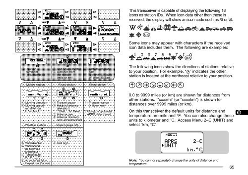
This transceiver is capable of displaying the following 18 icons as station IDs. When icon data other than these is received, the display will show an icon code such as /$ or \$. 1 2 3 Some icons may appear with characters if the received icon data includes them. The following are examples: 4 5 6 7 q Position comment (or status text) Mobile station q Grid square locator w Distance from the station (mile or km) Fixed station q Latitude/ longitude data N: North S: South W: West E: East Fixed station 1 The following icons show the directions of stations relative to your position. For example, “ ” indicates the other station is located at the northeast relative to your position. 8 9 10 11 12 q Moving direction w Moving speed m: Mile/hour k: km/hour Weather station q Transmit power w Height of antenna (elevation) ’ : Feet M: Meter e Antenna gain r Antenna directivity omni: Omnidirectional Object {page 63} q Transmit range (mile or km) 1 Using compressed APRS data format 0.0 to 9999 miles (or km) are shown for distances from other stations. “xxxxmi” (or “xxxxkm”) is shown for distances over 9999 miles (or km). On this transceiver the default units for distance and temperature are mile and °F. You can also change these units to kilometer and °C. Access Menu 2–C (UNIT) and select “km, °C”. 13 14 15 16 17 18 5 STA CON 7 9 96 BCONDUP 19 20 q Wind direction w Wind speed m: Mile/hour k: km/hour e Temperature F: ° F c: °C r Amount of rainfall in the past hour (" or mm) q Call sign Note: You cannot separately change the units of distance and temperature. 65 21 22 23
- Page 21 and 22: KEYPAD DIRECT ENTRY The keypad allo
- Page 23 and 24: First select the desired band. Key
- Page 25 and 26: MENU CONFIGURATION Level 1 Level 2
- Page 27 and 28: Level 1 Level 2 3 SSTV 4 SKY CMD (T
- Page 29 and 30: PROGRAMMING OFFSET First select ban
- Page 31 and 32: AUTOMATIC REPEATER OFFSET This func
- Page 33 and 34: TONE FREQ. ID This function scans t
- Page 35 and 36: STORING SIMPLEX FREQUENCIES OR STAN
- Page 37 and 38: NAMING A MEMORY CHANNEL You can nam
- Page 39 and 40: MEMORY-TO-VFO TRANSFER You may some
- Page 41 and 42: SCAN Scan is a useful feature for h
- Page 43 and 44: VFO SCAN VFO Scan monitors all freq
- Page 45 and 46: PROGRAM SCAN Program Scan is identi
- Page 47 and 48: CONTINUOUS TONE CODED SQUELCH SYSTE
- Page 49 and 50: DUAL TONE MULTI-FREQUENCY (DTMF) FU
- Page 51 and 52: ■ Transmitting a Stored DTMF Numb
- Page 53 and 54: AUXILIARY FUNCTIONS DIRECT FREQUENC
- Page 55 and 56: TONE ALERT Tone Alert provides an a
- Page 57 and 58: AUTOMATIC POWER OFF (APO) Automatic
- Page 59 and 60: TX INHIBIT You can disable the tran
- Page 61 and 62: CONNECTING WITH A PERSONAL COMPUTER
- Page 63 and 64: SELECTING DATA BAND This transceive
- Page 65 and 66: SLOW-SCAN TELEVISION (SSTV) WITH VC
- Page 67 and 68: SELECTING COLOR FOR CALL SIGN/ MESS
- Page 69 and 70: AUTOMATIC PACKET/ POSITION REPORTIN
- Page 71: RECEIVING APRS DATA Each time new A
- Page 75 and 76: SELECTING YOUR STATION ICON Select
- Page 77 and 78: SELECTING A POSITION COMMENT The AP
- Page 79 and 80: PROGRAMMING A GROUP CODE Using a gr
- Page 81 and 82: Let us describe four basic methods
- Page 83 and 84: SELECTING BEACON TRANSMIT INTERVAL
- Page 85 and 86: RECEIVING A MESSAGE Each time a pro
- Page 87 and 88: ENTERING A MESSAGE You can enter a
- Page 89 and 90: WIRELESS REMOTE CONTROL (TH-D7A ONL
- Page 91 and 92: SKY COMMAND 2 (TH-D7A ONLY) The Sky
- Page 93 and 94: PREPARATION FLOW The following step
- Page 95 and 96: CONTROL OPERATION When in the Sky C
- Page 97 and 98: MAINTENANCE GENERAL INFORMATION Thi
- Page 99 and 100: Problem Probable Cause Corrective A
- Page 101 and 102: Problem Operating the Commander sim
- Page 103 and 104: PG-3J Filtered Cigarette Lighter Ca
- Page 105 and 106: SPECIFICATIONS General VHF Band UHF
- Page 107 and 108: TNC COMMANDS LIST APPENDIX The comm
- Page 109 and 110: 101 Name ommand C t hor S t efaul D
- Page 111: Accessories Optional ..............
This transceiver is capable of displaying the following 18<br />
icons as station IDs. When icon data other than these is<br />
received, the display will show an icon code such as /$ or \$.<br />
1<br />
2<br />
3<br />
Some icons may appear with characters if the received<br />
icon data includes them. The following are examples:<br />
4<br />
5<br />
6<br />
7<br />
q Position<br />
comment<br />
(or status text)<br />
Mobile station<br />
q Grid square locator<br />
w Distance from<br />
the station<br />
(mile or km)<br />
Fixed station<br />
q Latitude/ longitude<br />
data<br />
N: North S: South<br />
W: West E: East<br />
Fixed station 1<br />
The following icons show the directions of stations relative<br />
to your position. For example, “ ” indicates the other<br />
station is located at the northeast relative to your position.<br />
8<br />
9<br />
10<br />
11<br />
12<br />
q Moving direction<br />
w Moving speed<br />
m: Mile/hour<br />
k: km/hour<br />
Weather station<br />
q Transmit power<br />
w Height of antenna<br />
(elevation)<br />
’ : Feet M: Meter<br />
e Antenna gain<br />
r Antenna directivity<br />
omni: Omnidirectional<br />
Object {page 63}<br />
q Transmit range<br />
(mile or km)<br />
1 Using compressed<br />
APRS data format<br />
0.0 to 9999 miles (or km) are shown for distances from<br />
other stations. “xxxxmi” (or “xxxxkm”) is shown for<br />
distances over 9999 miles (or km).<br />
On this transceiver the default units for distance and<br />
temperature are mile and °F. You can also change these<br />
units to kilometer and °C. Access Menu 2–C (UNIT) and<br />
select “km, °C”.<br />
13<br />
14<br />
15<br />
16<br />
17<br />
18<br />
5<br />
STA CON<br />
7 9<br />
96 BCONDUP<br />
19<br />
20<br />
q Wind direction<br />
w Wind speed<br />
m: Mile/hour<br />
k: km/hour<br />
e Temperature<br />
F: ° F c: °C<br />
r Amount of rainfall in<br />
the past hour (" or mm)<br />
q Call sign<br />
Note: You cannot separately change the units of distance and<br />
temperature.<br />
65<br />
21<br />
22<br />
23


