Optima Canopy group configurations instructions - Armstrong
Optima Canopy group configurations instructions - Armstrong
Optima Canopy group configurations instructions - Armstrong

Create successful ePaper yourself
Turn your PDF publications into a flip-book with our unique Google optimized e-Paper software.
ENGLISH<br />
Installation Instructions for <strong>Optima</strong> <strong>Canopy</strong> Group Configuration<br />
Note: Dimensions in mm may look strange, but are the exact conversion from US inches and feet into millimetres.<br />
For example:<br />
Distance between corner holes on the back of the <strong>Canopy</strong> is 610 mm.<br />
The length of a Grouping Frame is 3658 mm.<br />
Spacing between holes in the <strong>group</strong>ing frame is 51 mm.<br />
Maximum spacing between 2 aircraft cables is 1219 mm.<br />
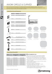
<strong>Optima</strong> <strong>Canopy</strong> Group Configuration Components<br />
<strong>Optima</strong> Canopies Grouping Frame: 3658mm U shaped section<br />
used to support <strong>Optima</strong> Canopies in <strong>group</strong> <strong>configurations</strong> with predrilled<br />
holes at 51 mm centres.<br />
Frame Splice: 254 mm long splice to join lengths of Grouping<br />
Frame together.<br />
Frame Alignment Spacer: Bracket to ensure 90° alignment of<br />
perpendicular Grouping Frame sections.<br />
Soffit Hanging Kit: Aircraft cable with Bottom End Cable adjuster,<br />
Gripper Structure Anchor and Cap to hang <strong>Optima</strong> <strong>Canopy</strong> <strong>group</strong><br />
<strong>configurations</strong> from the structural soffit.<br />
Escutcheon Kit: Cover plate to conceal the Gripper Structure<br />
assembly when installing <strong>Optima</strong> <strong>Canopy</strong> <strong>group</strong> <strong>configurations</strong> below<br />
an existing ceiling.<br />
Panel Hooks: Two sizes of hooks (‘high’ and ‘low’) that attach to<br />
the back of the <strong>Canopy</strong> and are hooked over the Grouping Frame<br />
assembly to suspend the Canopies.<br />
Bolt with Washer<br />
Grouping Frame Assembly<br />
From the different Grouping Options drawings, determine the<br />
required length(s) of the Grouping Frame component, and cut them<br />
with a hacksaw.<br />
Frames need to extend 51 mm past the point where the panel<br />
hooks will engage them, to ensure that the hooks will not slip off<br />
the frames.<br />
For Grouping Frame lengths greater than 3658 mm, use a Frame<br />
Splice with nut, bolt and washer to join two sections of <strong>group</strong>ing<br />
frame together.<br />
Where the cut edge of a Grouping Frame may be visible, black<br />
paint or a black marker can be used to disguise it.<br />
Tip: Frame on centre<br />
line of 51 mm<br />
hole spacing<br />
Grouping Frame<br />
Nut<br />
254 mm Frame Splice<br />
The lower Grouping Frame sections should be installed with the ‘U’<br />
shape down and are the ones that will be suspended from the<br />
structure.<br />
The upper Grouping Frame sections should be installed with the<br />
‘U’ shape up and are supported by the lower sections.<br />
Where Grouping Frames cross each other, use a Frame Alignment<br />
Spacer to establish 90° alignment with nuts and bolts to secure the<br />
connection.<br />
Pass the bottom end of the aircraft cable through both the Gripper<br />
Structure Cap and Bottom End Adjuster. Attach the aircraft cables<br />
to the lower Grouping Frame at 1219 mm maximum centres by<br />
inserting the Bottom End Cable Adjuster into a pre-drilled hole and<br />
secure it with a nut, bolt and washer.<br />
Aircraft Cable<br />
to Soffit<br />
Bottom End Cable<br />
Adjuster<br />
“Lower” Grouping<br />
Frame<br />
Screw<br />
“Upper” Grouping<br />
Frame<br />
Frame Alignment<br />
Spacer<br />
Nut with Washer<br />
Nut with Washer<br />
2