Optima Canopy group configurations instructions - Armstrong
Optima Canopy group configurations instructions - Armstrong
Optima Canopy group configurations instructions - Armstrong

Create successful ePaper yourself
Turn your PDF publications into a flip-book with our unique Google optimized e-Paper software.
<strong>Optima</strong> <strong>Canopy</strong> Accessories for Suspension<br />
Accessory Kits – Applications always require more than one kit. Please review your needs carefully.<br />
Item No.<br />
Kit Contents<br />
BPCS5450G Soffit Hanging Kit<br />
Allows for suspending individual shapes or <strong>group</strong>ing frames from<br />
soffit and bottom end adjustment of height at panel or frame level.<br />
(2) gripper structure anchors<br />
(2) gripper structure caps<br />
(2) 2438mm aircraft cables<br />
(2) bottom end cable adjusters<br />
(2) nuts with washers<br />
Item No. Kit Contents<br />
BPCS5454G Panel Hook Kit<br />
For use with <strong>group</strong> frames, one kit per panel.<br />
(2) 114 mm high panel hooks, black<br />
(2) 89 mm high panel hooks, black<br />
(8) bolts<br />
ENGLISH<br />
Item No. Kit Contents<br />
BPCS5451G Grouping Frames<br />
Suspension frames used to <strong>group</strong> panels together<br />
(4) suspension frames, 3658 mm long, black<br />
Item No. Kit Contents<br />
BPCS5455G Drywall Hanging Kit<br />
For individual panel attachment to drywall<br />
(2) drywall clip assemblies<br />
(2) shoulder bolts<br />
Item No. Kit Contents<br />
BPCS5452G Frame Splice Kit<br />
Connects <strong>group</strong> suspension frames for longer runs<br />
(>3658 mm)<br />
(2) <strong>group</strong> frame connectors,<br />
254 mm long, black<br />
(4) bolts with washers<br />
(4) nuts<br />
Item No. Kit Contents<br />
BP625530G Extended Hanging Cables<br />
For use with soffit hanging kit when longer cables are needed<br />
(4) 9144 mm aircraft cables<br />
Item No. Kit Contents<br />
BP7006<br />
Escutcheon Kit<br />
Used when hanging panels below an existing ceiling<br />
(2) collars with set screws<br />
(2) 51 mm escutcheons<br />
Item No.<br />
Kit Contents<br />
BPCS5453G Frame Alignment Kit<br />
For use with <strong>group</strong> suspension frames<br />
(4) frame alignment spacers,<br />
clear plastic<br />
(4) bolts<br />
(4) nuts with washers<br />
NOTE: If you need assistance identifying what and how<br />
many accessory kits are needed for your project, please<br />
contact our Internal Technical Sales <strong>group</strong> or visit<br />
www.armstrong-ceilings.co.uk<br />
or<br />
www.armstrong-ceilings.ie.<br />
1
ENGLISH<br />
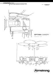
Installation Instructions for <strong>Optima</strong> <strong>Canopy</strong> Group Configuration<br />
Note: Dimensions in mm may look strange, but are the exact conversion from US inches and feet into millimetres.<br />
For example:<br />
Distance between corner holes on the back of the <strong>Canopy</strong> is 610 mm.<br />
The length of a Grouping Frame is 3658 mm.<br />
Spacing between holes in the <strong>group</strong>ing frame is 51 mm.<br />
Maximum spacing between 2 aircraft cables is 1219 mm.<br />
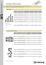
<strong>Optima</strong> <strong>Canopy</strong> Group Configuration Components<br />
<strong>Optima</strong> Canopies Grouping Frame: 3658mm U shaped section<br />
used to support <strong>Optima</strong> Canopies in <strong>group</strong> <strong>configurations</strong> with predrilled<br />
holes at 51 mm centres.<br />
Frame Splice: 254 mm long splice to join lengths of Grouping<br />
Frame together.<br />
Frame Alignment Spacer: Bracket to ensure 90° alignment of<br />
perpendicular Grouping Frame sections.<br />
Soffit Hanging Kit: Aircraft cable with Bottom End Cable adjuster,<br />
Gripper Structure Anchor and Cap to hang <strong>Optima</strong> <strong>Canopy</strong> <strong>group</strong><br />
<strong>configurations</strong> from the structural soffit.<br />
Escutcheon Kit: Cover plate to conceal the Gripper Structure<br />
assembly when installing <strong>Optima</strong> <strong>Canopy</strong> <strong>group</strong> <strong>configurations</strong> below<br />
an existing ceiling.<br />
Panel Hooks: Two sizes of hooks (‘high’ and ‘low’) that attach to<br />
the back of the <strong>Canopy</strong> and are hooked over the Grouping Frame<br />
assembly to suspend the Canopies.<br />
Bolt with Washer<br />
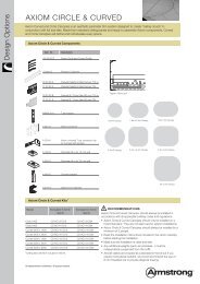
Grouping Frame Assembly<br />
From the different Grouping Options drawings, determine the<br />
required length(s) of the Grouping Frame component, and cut them<br />
with a hacksaw.<br />
Frames need to extend 51 mm past the point where the panel<br />
hooks will engage them, to ensure that the hooks will not slip off<br />
the frames.<br />
For Grouping Frame lengths greater than 3658 mm, use a Frame<br />
Splice with nut, bolt and washer to join two sections of <strong>group</strong>ing<br />
frame together.<br />
Where the cut edge of a Grouping Frame may be visible, black<br />
paint or a black marker can be used to disguise it.<br />
Tip: Frame on centre<br />
line of 51 mm<br />
hole spacing<br />
Grouping Frame<br />
Nut<br />
254 mm Frame Splice<br />
The lower Grouping Frame sections should be installed with the ‘U’<br />
shape down and are the ones that will be suspended from the<br />
structure.<br />
The upper Grouping Frame sections should be installed with the<br />
‘U’ shape up and are supported by the lower sections.<br />
Where Grouping Frames cross each other, use a Frame Alignment<br />
Spacer to establish 90° alignment with nuts and bolts to secure the<br />
connection.<br />
Pass the bottom end of the aircraft cable through both the Gripper<br />
Structure Cap and Bottom End Adjuster. Attach the aircraft cables<br />
to the lower Grouping Frame at 1219 mm maximum centres by<br />
inserting the Bottom End Cable Adjuster into a pre-drilled hole and<br />
secure it with a nut, bolt and washer.<br />
Aircraft Cable<br />
to Soffit<br />
Bottom End Cable<br />
Adjuster<br />
“Lower” Grouping<br />
Frame<br />
Screw<br />
“Upper” Grouping<br />
Frame<br />
Frame Alignment<br />
Spacer<br />
Nut with Washer<br />
Nut with Washer<br />
2
Suspending the Grouping Frame Assembly<br />
- To the structural soffit:<br />
Attach the Gripper Structure Anchor to the<br />
soffit using appropriate fixings (by others).<br />
Screw the Gripper Structure Cap into the Gripper Structure Anchor.<br />
Note: Soffit attachment hardware by others<br />
Gripper Structure Anchor<br />
Aircraft Cable<br />
Gripper Structure Cap<br />
ENGLISH<br />
Cable attaches to Grouping<br />
Frame below via the Bottom<br />
End Cable Adjuster<br />
- Below an existing suspended ceiling:<br />
The Gripper Structure Anchor must be mounted to a support at or<br />
above the existing ceiling.<br />
Use 6 mm threaded rod attached to the structure to secure the<br />
Gripper Structure Anchor at the correct height and diagonal bracing<br />
to structure to provide support.<br />
Use the optional accessory Escutcheon Kit to conceal the structure<br />
gripper anchor when installed above the ceiling level. The collets<br />
support the Escutcheon Cover Plate and are secured to the aircraft<br />
cable using the grub screws in the collets.<br />
NB: The aircraft cable must be passed through the Escutcheons in<br />
stage 2 after it is passed through the Gripper Structure Cap but<br />
before it is fed through the Bottom End Adjuster.<br />
Gripper<br />
Structure<br />
Anchor<br />
Escutcheon<br />
Threaded Rod<br />
not included<br />
Escutcheon Kit<br />
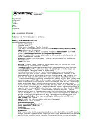
Attaching the Panel Hooks to the Canopies<br />
You need 4 hooks (2 ‘high’ + 2 ‘low’) for each panel with the exception<br />
of the 1200 x 2400 mm (nominal) panel which requires 6 hooks. The<br />
‘high’ hooks attach the <strong>Canopy</strong> to the upper Grouping Frame section<br />
and the ‘low’ hooks to the lower Grouping Frame section.<br />
If the <strong>Canopy</strong> shape is not symmetrical, you must determine where the<br />
high and low hooks need to be placed to meet the design layout. Hooks<br />
of the same height are always on opposite sides to each other.<br />
The back channel of the <strong>Canopy</strong> is marked at centre and 203 mm off<br />
centre to assist with hook placement.<br />
Different layouts will require Panel Hooks to be installed either centrally<br />
on all 4 sides or centrally on 2 sides and offset by 203 mm on the 2<br />
other sides. Refer to the Grouping Options layout drawings to<br />
determine the correct location of the Panel Hooks.<br />
There is a notch cut into the base of the hooks which should be lined up<br />
with the appropriate mark on the back channel of the <strong>Canopy</strong>.<br />
This notch should always be facing the outside of the <strong>Canopy</strong><br />
The nuts for securing the hooks to the frames are already<br />
located in the back channels.<br />
Line up those nuts and screw the Panel Hooks to the back<br />
channel of the <strong>Canopy</strong> with the Panel Hook bolts.<br />
Central mark<br />
Mark 203 mm off-centre<br />
Panel Hook<br />
Screw attaches to inside<br />
back-channel square nut<br />
Back-channel marked at<br />
centre and 203 mm O.C.<br />
to assist with hook<br />
placement<br />
Note: Use hook locater to correctly<br />
place hooks at pre-marked locations<br />
Important: The screws and nuts supplied have an American diameter and the standard European size will not fit.<br />
If they get lost, you can order the BPCS6350G Spare Parts Kit (with 4 shoulder bolts, 4 screws for panel hook kit, 4 nuts with washers)<br />
3
ENGLISH<br />
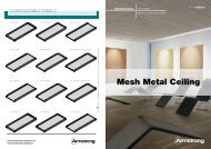
Hanging the Canopies from the Grouping Frame Assembly<br />
1) With the <strong>Canopy</strong> below the intersection of the upper and lower<br />
Grouping Frames, rotate the panel so that it is about 10°<br />
clockwise off the alignment of the Grouping Frame sections.<br />
Ensure that the ‘high’ Panel Hooks are next to the upper<br />
Grouping Frame and that the ‘low’ Panel Hooks are next to<br />
the lower Grouping Frame.<br />
4) Let the panel drop carefully into place with the four panel<br />
hooks engaging the upper and lower frames.<br />
5) Repeat as necessary for the number of panels you have in<br />
your <strong>group</strong> configuration.<br />
2) Lift the <strong>Canopy</strong> until the back channel metal extrusion touches<br />
the underside of the lower Grouping Frame. Start rotating the<br />
panel in a counter-clockwise direction, as shown in the diagram.<br />
Installing shapes below an<br />
existing suspended ceiling<br />
3) When the panel is rotated about 10°, the bottom of the hooks<br />
should engage the <strong>group</strong>ing frames.<br />
<strong>Canopy</strong> suspension cables should not<br />
impose any additional load or lateral<br />
force on an existing ceiling.<br />
1) The Gripper Structure Anchor must be mounted to a<br />
structural support at or above the existing ceiling.<br />
2) Use 6 mm threaded rod (1) attached to the<br />
structure to secure the Gripper Structure<br />
Anchor (2) at the correct height.<br />
3) Use diagonal bracing to structure to<br />
support and lateral restraint.<br />
4) Use the optional Escutcheon<br />
Accessory Kit (3) to conceal the<br />
Gripper Structure Anchor when<br />
installed above the ceiling level.<br />
Escutcheon Kit<br />
4
NECESSARY ITEMS FOR GROUP CONFIGURATIONS<br />
4-Panel Square Group Layouts<br />
To create these kinds of <strong>group</strong>s with a minimum of 51 mm spacing between shapes, you need to order:<br />
ENGLISH<br />
A1 A2 A3 A4 A5 A6 A7 A8<br />
(4) shapes: (4) BPCS5441WHG (4) BPCS5442WHG (4) BPCS5440WHG (4) BPCS5443WHG (4) BPCS5444WHG (4) BPCS5445WHG (4) BPCS5446WHG (4) BPCS5447WHG<br />
+<br />
(2) BPCS5450G Soffit Hanging Kits (1) BPCS5453G Frame Alignment Kit<br />
(1) BPCS5451G Grouping Frames Kit (4) BPCS5454G Panel Hook Kits<br />
4-Panel Linear Group Layouts<br />
To create these kinds of <strong>group</strong>s with a minimum of 51 mm spacing between shapes, you need to order:<br />
B1 B2 B3 B4 B5 B6 B7 B8 B9 B10 B11<br />
(4) shapes: (2) BPCS5441WHG (4) BPCS5441WHG (4) BPCS5442WHG (4) BPCS5440WHG (4) BPCS5443WHG (4) BPCS5444WHG (4) BPCS5445WHG (4) BPCS5447WHG (4) BPCS5446WHG (2) BPCS5446WHG 2) BPCS5445WHG<br />
(2) BPCS5442WHG (2) BPCS5447WHG (1) BPCS5446WHG<br />
+ (1) BPCS5447WHG<br />
(3) BPCS5450G Soffit Hanging Kits (1) BPCS5452G Frame Splice Kit<br />
(2) BPCS5451G Grouping Frame Kits (4) BPCS5454G Panel Hook Kits<br />
(2) BPCS5453G Frame Alignment Kit<br />
9-Panel Square Group Layouts<br />
To create these kinds of <strong>group</strong>s with a minimum of 51 mm spacing between shapes, you need to order:<br />
C1 C2 C3 C4 C5 C6 C7 C8 C9 C10<br />
(9) shapes: (5) BPCS5441WHG (9) BPCS5440WHG (9) BPCS5443WHG (5) BPCS5440WHG (9) BPCS5444WHG (9) BPCS5445WHG (9) BPCS5446WHG (9) BPCS5447WHG (6) BPCS5446WHG (3) BPCS5445WHG<br />
(4) BPCS5442WHG (4) BPCS5443WHG (3) BPCS5447WHG (3) BPCS5446WHG<br />
+ (3) BPCS5447WHG<br />
(5) BPCS5450G Soffit Hanging Kits (3) BPCS5453G Frame Alignment Kits<br />
(2) BPCS5451G Grouping Frame Kits (9) BPCS5454G Panel Hook Kits<br />
4-Panel Rectangular Layout<br />
7-Panel Circular Layout<br />
To create these kinds of <strong>group</strong>s with a minimum of 51 mm spacing between shapes, you need to order:<br />
D1 E1 E2<br />
(4) shapes: (2) BPCS5440WHG & (2) BPCS5448WHG<br />
+<br />
(3) BPCS5450G Soffit Hanging Kits<br />
(1) BPCS5451G Grouping Frame Kit<br />
(1) BPCS5453G Frame Alignment Kit<br />
(4) BPCS5454G Panel Hook Kits<br />
(7) shapes: (7) BPCS5444WHG or (7) BPCS5443WHG<br />
+<br />
(5) BPCS5450G Soffit Hanging Kits<br />
(2) BPCS5451G Grouping Frame Kit<br />
(3) BPCS5453G Frame Alignment Kit<br />
(7) BPCS5454G Panel Hook Kits<br />
NOTE: See Grouping Installation Instructions for details on typical <strong>group</strong> <strong>configurations</strong>.<br />
If you need assistance identifying what and how many accessory kits are needed for your project, please contact our Internal Technical Sales Group or visit<br />
www.armstrong-ceilings.co.uk or www.armstrong-ceilings.ie<br />
5
ENGLISH<br />
A1<br />
1219 mm<br />
A2<br />
1219 mm<br />
108mm<br />
159 mm<br />
1219 mm<br />
1219 mm<br />
108 mm<br />
159 mm<br />
A3<br />
1219 mm<br />
A4<br />
1219 mm<br />
1219 mm<br />
51 mm<br />
1219 mm<br />
51 mm<br />
51 mm<br />
51 mm<br />
A5<br />
1219 mm<br />
A6<br />
1219 mm<br />
1219 mm<br />
210 mm<br />
1219 mm<br />
51 mm<br />
57 mm<br />
203 mm<br />
A7<br />
1219 mm<br />
1219 mm<br />
203 mm<br />
51 mm<br />
A8<br />
1219 mm<br />
1219 mm<br />
51 mm<br />
51 mm<br />
x = panel hook locations during installation<br />
• = recommended hanging point location<br />
Frame lengths:<br />
1 1930 mm<br />
Notes:<br />
Add or subtract 51 mm to frame length<br />
dimensions for each 51 mm increase /<br />
decrease in spacing between panels.<br />
General notes:<br />
Always hang <strong>group</strong>ing frame from lower<br />
frame member.<br />
Hanging point spacing along frame not to<br />
exceed 1219 mm.<br />
6
B1<br />
406 mm<br />
B2<br />
406mm<br />
B3<br />
406mm<br />
B4<br />
406 mm<br />
ENGLISH<br />
114 mm<br />
1219 mm<br />
1219 mm<br />
1219 mm<br />
1219 mm<br />
108 mm<br />
102 mm<br />
51 mm<br />
1219 mm<br />
108 mm<br />
1219 mm<br />
114 mm<br />
1219 mm<br />
102 mm<br />
1219 mm<br />
51 mm<br />
114 mm<br />
1219 mm<br />
108 mm<br />
1219 mm<br />
1219 mm<br />
102 mm<br />
1219 mm<br />
51 mm<br />
B5<br />
406 mm<br />
B6<br />
406mm<br />
B7<br />
406 mm<br />
B8<br />
406 mm<br />
1219 mm<br />
1219 mm<br />
1219 mm<br />
1219 mm<br />
51 mm<br />
210 mm<br />
51 mm<br />
203 mm<br />
1219 mm<br />
51 mm<br />
1219 mm<br />
210 mm<br />
1219 mm<br />
51 mm<br />
1219 mm<br />
203 mm<br />
1219 mm<br />
51 mm<br />
1219 mm<br />
210 mm<br />
1219 mm<br />
51 mm<br />
1219 mm<br />
203 mm<br />
B9<br />
1219 mm<br />
1219 mm<br />
1219 mm<br />
406 mm<br />
51 mm<br />
51 mm<br />
51 mm<br />
B10<br />
1219 mm<br />
1219 mm<br />
1219 mm<br />
406 mm<br />
51 mm<br />
51 mm<br />
51 mm<br />
B11<br />
1219 mm<br />
1219 mm<br />
1219 mm<br />
406 mm<br />
203 mm<br />
203 mm<br />
203 mm<br />
x = panel hook locations during installation<br />
• = recommended hanging point location<br />
0 = 254mm frame splice<br />
Frame lengths:<br />
1 1016 mm<br />
2 3353 mm<br />
3 711 mm<br />
Notes:<br />
Add or subtract 152 mm to overall<br />
(4369 mm) frame length dimensions for<br />
each 51 mm increase / decrease in<br />
spacing between panels.<br />
406 mm dimension will remain unchanged<br />
regardless of visual spacing.<br />
254 mm splice is required for frame lengths<br />
longer that 3658 mm.<br />
General notes:<br />
Always hang <strong>group</strong>ing frame from lower<br />
frame member.<br />
Hanging point spacing along frame not to<br />
exceed 1219 mm.<br />
7
ENGLISH<br />
C1<br />
1219 mm<br />
1219 mm<br />
C2<br />
1219 mm<br />
1219 mm<br />
1219 mm<br />
108 mm<br />
1219 mm<br />
51 mm<br />
1219 mm<br />
108 mm<br />
1219 mm<br />
51 mm<br />
171 mm 171 mm<br />
51 mm 51 mm<br />
1219 mm 1219 mm<br />
C3 1219 mm 1219 mm<br />
C4<br />
1219 mm<br />
51 mm<br />
1219 mm<br />
51mm<br />
1219 mm<br />
51 mm<br />
1219 mm<br />
51mm<br />
51 mm 51 mm<br />
51mm<br />
51mm<br />
C5<br />
1219 mm<br />
1219 mm<br />
1219 mm<br />
1219 mm<br />
210 mm<br />
210 mm<br />
x = panel hook locations during installation<br />
• = recommended hanging point location<br />
Frame lengths:<br />
1 3150 mm<br />
Notes:<br />
Add or subtract 102 mm to frame length dimensions for each<br />
51 mm increase / decrease in spacing between panels.<br />
As visual spacing increases, use 254 mm splice as needed.<br />
General notes:<br />
Always hang <strong>group</strong>ing frame from lower frame member.<br />
Hanging point spacing along frame not to exceed 1219 mm.<br />
57 mm 57 mm<br />
8
C6<br />
1219 mm 1219 mm<br />
C7<br />
1219 mm 1219 mm<br />
ENGLISH<br />
51 mm<br />
203mm<br />
1219 mm<br />
1219 mm<br />
51 mm<br />
203mm<br />
1219 mm<br />
1219 mm<br />
203 mm 203 mm<br />
51mm<br />
51mm<br />
C8<br />
1219 mm<br />
1219 mm<br />
C9<br />
1219mm<br />
1219mm<br />
51mm<br />
203mm<br />
1219 mm<br />
1219mm<br />
51mm<br />
203mm<br />
1219 mm<br />
1219mm<br />
203 mm 203 mm<br />
51mm<br />
51mm<br />
C10<br />
1219 mm<br />
1219 mm<br />
1219 mm<br />
1219 mm<br />
203 mm<br />
203 mm<br />
x = panel hook locations during installation<br />
• = recommended hanging point location<br />
Frame lengths:<br />
1 3150 mm<br />
Notes:<br />
Add or subtract 102 mm to frame length dimensions for each<br />
51 mm increase / decrease in spacing between panels.<br />
As visual spacing increases, use 254 mm splice as needed.<br />
General notes:<br />
Always hang <strong>group</strong>ing frame from lower frame member.<br />
Hanging point spacing along frame not to exceed 1219 mm.<br />
51 mm 51 mm<br />
9
ENGLISH<br />
D1<br />
1219 mm<br />
1829 mm<br />
51 mm<br />
x = panel hook locations during installation<br />
• = recommended hanging point location<br />
0 = 254 mm frame splice<br />
Frame lengths:<br />
1 1930 mm<br />
2 2540 mm<br />
Notes:<br />
Add or subtract 51 mm to frame length dimensions for each 51 mm<br />
increase / decrease in spacing between panels.<br />
As visual spacing increases, use 254 mm splice as needed.<br />
General notes:<br />
Always hang <strong>group</strong>ing frame from lower frame member.<br />
Hanging point spacing along frame not to exceed 1219 mm.<br />
51 mm<br />
E1<br />
2134 mm<br />
864 mm<br />
406 mm<br />
864 mm<br />
610 mm<br />
610 mm<br />
184 mm<br />
1219 mm<br />
610 mm<br />
610 mm<br />
197 mm<br />
E2<br />
610 mm<br />
610 mm<br />
1219 mm<br />
610 mm<br />
610 mm<br />
2134 mm<br />
406 mm<br />
864 mm 864 mm<br />
57 mm<br />
51 mm<br />
x = panel hook locations during installation<br />
• = recommended hanging point location<br />
Frame lengths:<br />
1 1930 mm<br />
2 3150 mm<br />
3 711 mm<br />
4 2845 mm<br />
Notes:<br />
Add or subtract 152 mm to overall (4369 mm) frame length<br />
dimensions for each 51 mm increase / decrease in spacing<br />
between panels add or subtract from the frame length dimensions<br />
as follows:<br />
frame 1 51 mm<br />
frame 2 102 mm<br />
frame 3 stays the same<br />
frame 4 51 mm<br />
General notes:<br />
Always hang <strong>group</strong>ing frame from lower frame member.<br />
Hanging point spacing along frame not to exceed 1219 mm.<br />
10