ASH 26 E Flight Manual 4.8 - Alexander Schleicher
ASH 26 E Flight Manual 4.8 - Alexander Schleicher
ASH 26 E Flight Manual 4.8 - Alexander Schleicher

Create successful ePaper yourself
Turn your PDF publications into a flip-book with our unique Google optimized e-Paper software.
<strong>ASH</strong> <strong>26</strong> E <strong>Flight</strong> <strong>Manual</strong><br />
i) Any kinks in Bowden cables or fuel lines and hoses? Elastic cords of<br />
the engine bay doors in good condition?<br />
j) Inspect hoses (especially fuel and coolant hoses) and all components<br />
for signs of chafing.<br />
k) Check carburettor and air filter for secure seating.<br />
l) Check limit switch for electric jack for damage and secure seating -<br />
including its electric connectors.<br />
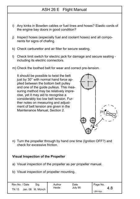
m) Check the toothed belt for wear and correct pre-tension.<br />
It should be possible to twist the belt<br />
just by 30° with normal hand force applied<br />
between the bottom belt pulley<br />
and one of the guide pulleys. This measuring<br />
method may be relatively imprecise,<br />
yet it may aid to recognise a<br />
considerably too low belt tension. Further<br />
notes on measuring and adjustment<br />
of belt tension are given in the<br />
Maintenance <strong>Manual</strong>, Section 2. 30°<br />
n) Turn the propeller through by hand one time (Ignition OFF?) and<br />
check for excessive friction.<br />
Visual Inspection of the Propeller<br />
a) Visual inspection of the propeller as per propeller manual.<br />
b) Visual inspection of propeller mounting.<br />
Rev.No. / Date Sig.<br />
TN 15 Jan. 08 M. Münch<br />
Author<br />
Heide<br />
Date<br />
July 95<br />
Page No.<br />
LBA-App.<br />
<strong>4.8</strong>
<strong>ASH</strong> <strong>26</strong> E Maintenance <strong>Manual</strong><br />
completely covered by neatly fitting doors.<br />
2.3.1.2 Engine controls in the cockpit<br />
The throttle and the propeller stop block are operated via Bowden<br />
cables by a pair of control levers in the engine control console which is<br />
fitted beneath the instrument panel. Also the PRIMER and STARTER<br />
buttons and the main switch are located at this engine control console<br />
(see also <strong>Flight</strong> <strong>Manual</strong> Section 7.9 for a complete description and<br />
illustration of this console).<br />
The power-plant as well as the propeller extension and retraction are<br />
controlled by the ILEC-Power-Plant Control Unit (see also <strong>Flight</strong> <strong>Manual</strong><br />
Section 7.9 for a complete description and illustration of this control<br />
unit).<br />
2.3.1.3 Propeller Gear and Timing Belt<br />
The timing belt uses a special type of gear contour and must only be<br />
replaced for the original SCHLEICHER part; the same applies to the<br />
four belt pulleys.<br />
The belt tension and the belt running is adjusted factory-made.<br />
As experience shows the adjusted belt tension remains constant over<br />
a long period of time. If during pre-flight check there is reason to believe<br />
that the belt tension is too low or if any assembly works make it<br />
necessary to re-adjust the belt tension, this is done according the<br />
specifications in the Mainenance Instruction “Adjusting the drive<br />
belt” (Section 12.6).<br />
Rev.No. / Date Sig.<br />
TN 15 / Jan. 08 M. Münch<br />
Author Date<br />
Page No.<br />
Heide 31.01.95 2.13
TN 15:<br />
<strong>ASH</strong> <strong>26</strong> E Maintenance <strong>Manual</strong><br />
The original text is being replaced by the Mainenance Instruction “Adjusting<br />
the drive belt” (Section 12.6)<br />
Rev.No. / Date Sig.<br />
TN 15 / Jan. 08 M. Münch<br />
Author Date<br />
Page No.<br />
Heide 31.01.95 2.14
TN 15:<br />
<strong>ASH</strong> <strong>26</strong> E Maintenance <strong>Manual</strong><br />
The original text is being replaced by the Mainenance Instruction “Adjusting<br />
the drive belt” (Section 12.6)<br />
Rev.No. / Date Sig.<br />
TN 15 / Jan. 08 M. Münch<br />
Author Date<br />
Page No.<br />
Heide 31.01.95 2.15
TN 15:<br />
<strong>ASH</strong> <strong>26</strong> E Maintenance <strong>Manual</strong><br />
The original text is being replaced by the Mainenance Instruction “Adjusting<br />
the drive belt” (Section 12.6)<br />
2.3.1.4 Oil and Fuel Systems<br />
- Total loss oil lubrication:<br />
The engine uses a total loss oil lubrication which is supplied by a metering<br />
pump [9]. This pump is located behind the water pump through<br />
which it is driven and which in turn is driven by the crank shaft. The oil<br />
metering pump uses two outputs, one to the engine main bearings<br />
direct and the other to the combustion chamber indirect via an inlet<br />
beneath the carburettor.<br />
Whenever the oil supply is disturbed this system must always be bled.<br />
Therefore, we do not recommend to invert the fuselage for any maintenance<br />
work because this will allow air to penetrate into the connection<br />
line between oil tank and metering pump. Also if the oil tank went<br />
completely empty it is necessary to re-bleed the system. If the tank<br />
has been emptied during engine operation it must be considered to<br />
overhaul the engine because it may have been running possibly some<br />
time without oil supply.<br />
WARNING: Failure to bleed the oil connection line to the metering<br />
pump may result in destruction of the engine.<br />
The oil for the total loss supply is filled into a tank [10] between engine<br />
and exhaust silencer.<br />
At the right side of this tank an oil level photo-electric diode [11] is<br />
fitted which activates a yellow warning light at the ILEC control unit in<br />
case of low oil level.<br />
Rev.No. / Date Sig.<br />
TN 15 / Jan. 08 M. Münch<br />
Author Date<br />
Page No.<br />
Heide 31.01.95 2.16
Fig.2.3-6 Belt Adjustment<br />
TN 15:<br />
<strong>ASH</strong> <strong>26</strong> E Maintenance <strong>Manual</strong><br />
The Fig. 2.3-6 is being replaced by the Mainenance Instruction “Adjusting<br />
the drive belt” (Section 12.6)<br />
Rev.No. / Date Sig.<br />
TN 15 / Jan. 08 M. Münch<br />
Author Date<br />
Page No.<br />
Heide 31.01.95 2.68
<strong>ASH</strong> <strong>26</strong> E Wartungshandbuch<br />
12.6 Maintenance Instructions<br />
The following Maintenance Instructions are established from time to<br />
time as required, in accordance with experience accumulated in operating<br />
the <strong>ASH</strong> <strong>26</strong> E. The Maintenance <strong>Manual</strong> is to be supplemented<br />
by inserting any new Maintenance Instruction which may have been<br />
issued for the <strong>ASH</strong> <strong>26</strong> E.<br />
The general Maintenance Instruction "PAINT CRACKS" dated June<br />
<strong>26</strong>, 1989, describes how to inspect, preserve, and repair the paint<br />
surface, respectively.<br />
The Maintenance Instruction A for the <strong>ASH</strong> <strong>26</strong> E (dated July 31,<br />
1995) describes how to replace the elastic plastic sealing strips at the<br />
control surface and flap gaps, as well as how to apply or replace the<br />
turbulators at the horizontal and vertical tailplanes.<br />
The Maintenance Instruction "Venting the oil pump" dated March<br />
25, 1997 describes the how to vent the oil pump at the power-plant.<br />
The Maintenance Instruction "Fuel" dated Aug. 19, 1999, describes<br />
the use of motor vehicle fuel types.<br />
The Maintenance Instruction „Adjusting the belt drive“ dated August<br />
27, 2007 describes adjusting the belt tension and the belt running.<br />
Änd.Nr. / Datum Sig.<br />
TN 8/15 / Jan. 08 M. Münch<br />
Autor Datum<br />
Seite Nr.<br />
Heide 31.01.95 12.8
Sheet<br />
1 of 3<br />
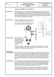
Maintenance Instruction<br />
Adjusting the drive belt<br />
Issue I<br />
Power-plant AE50R and IAE50R-AA<br />
<strong>Alexander</strong> <strong>Schleicher</strong><br />
GmbH & Co.<br />
Segelflugzeugbau<br />
D - 36163 Poppenhausen<br />
Subject: The belt tension is adjusted such that the belt eigenfrequency - in the area where it is<br />
running in the channel inside both swivel support arms - corresponds to 48 Hz. As experience<br />
shows the adjusted belt tension remains constant over a long period of time. If<br />
during pre-flight check there is reason to believe that the belt tension is too low or if any<br />
assembly works make it necessary to re-adjust the belt tension, this is done according to<br />
the procedure mentioned below:<br />
Preparation: Remove the side fairing of the swivel support<br />
arms as well as the propeller head fairing [1].<br />
Un-tighten the 4 lateral fixing screws [2] at the<br />
propeller head (only un-tighten them, do not<br />
remove).<br />
Initial adjustment: Prior to the fine tuning<br />
of the belt tension via<br />
its eigenfrequency, an<br />
initial adjustment is<br />
done using a spring<br />
scale.<br />
4<br />
5<br />
The belt deflection shall be approx. 9 mm [A] with a tensile load applied of F=58 N, to<br />
be measured at the point in the middle between the lower guide pulley [5] and the upper<br />
belt wheel [4],<br />
Change of the<br />
belt tension: The lock-nuts of the 3 tensioning screws [3] must be loosened. By evenly turning in<br />
and out respectively the 3 tensioning screws the prop head is moved parallel and thus<br />
the belt tension changed.<br />
If the propeller is fully extended, the belt tension makes it difficult to turn the tensioning<br />
screws. For adjusting the tensioning screws the propeller may be retracted a little,<br />
until the belt tension decreases.<br />
Fine adjustment: With the above described measuring method the adjusting tolerances of the belt tension<br />
are still relatively large. More exact results are achieved by measuring the eigenfrequency<br />
of the belt. This is done by "picking" the belt (like a guitar string) between<br />
the lower guide pulley [5] and the upper belt wheel [4]. Using a frequency meter the<br />
oscillation (eigenfrequency) of the belt is then measured.<br />
After the above described initial adjustment has been done the belt tension is increased<br />
by evenly turning in and out respectively the 3 tensioning screws [3] so that<br />
the belt eigenfrequency will become 48 Hz.<br />
A<br />
F<br />
½<br />
½
Sheet<br />
2 of 3<br />
Maintenance Instruction<br />
Adjusting the drive belt<br />
Issue I<br />
<strong>Alexander</strong> <strong>Schleicher</strong><br />
GmbH & Co.<br />
Segelflugzeugbau<br />
D - 36163 Poppenhausen<br />
Frequency<br />
Measurement: As frequency meters for the special purpose of<br />
measuring belt eigenfrequency are relatively expensive,<br />
there is a cheaper alternative: by means<br />
of a commercial quality chromatic guitar (bass-)<br />
tuning meter the belt eigenfrequency may also be<br />
measured and determined. Yet it is necessary to<br />
bring the belt tension before into the required<br />
range by the above described initial adjustment, as<br />
these meters do not indicate the frequency but the<br />
produced pitch. Then the fine adjustment of the<br />
belt tension is done until the tone „G“ (contra-G“)<br />
is reached which corresponds to the required<br />
48 Hz.<br />
These standard tuning meters however do not show to which octave the indicated<br />
tone belongs; so it would be imaginable that the belt inadvertently was adjusted into<br />
"one octave too high“, i.e. to the so-called G 1 . That would correspond to about 96 Hz<br />
and would be a much too high belt tension. Therefore, it is indispensable to do first<br />
the above described rough initial adjustment.<br />
Another alternative would be to use an existing notebook which features a sound card<br />
and a microphone. The measurement can then be done using any freeware Frequency<br />
Analyse Programme.<br />
Tensioning<br />
screws: If there is need to turn the tensioning<br />
screws with thread diameter M6 so far<br />
inside that more than 6 mm free screw<br />
thread are visible on leveling pads, then<br />
so-called back-up support nuts must be<br />
fitted and locked with each tensioning<br />
screw (see arrows in the Figure next to<br />
this text). This will prevent safely a<br />
failure of the tensioning screws due to<br />
oscillation fatigue.<br />
In order to fit the back-up support nuts first the lateral fixing screws [2] must be retightened<br />
and then the tensioning screws [3] must be turned back so far that the<br />
plugged-on dish end can be taken off and thus the support nut screwed on.<br />
After turning in again the 3 tensioning screws back to the previous position, the lateral<br />
fixing screws are un-tightened again and the belt tension must be checked once<br />
again.<br />
When the final position has been found, the tensioning screws are safely tightened<br />
and locked together with the upper support nut and the lower hexagon nut.<br />
Note: In case of power-plants which use tensioning screws with thread diameter<br />
M8, no back-up support nuts are fitted.
Sheet<br />
3 of 3<br />
Maintenance Instruction<br />
Adjusting the drive belt<br />
Issue I<br />
<strong>Alexander</strong> <strong>Schleicher</strong><br />
GmbH & Co.<br />
Segelflugzeugbau<br />
D - 36163 Poppenhausen<br />
Belt running: An increased wear occurs also if the belt is running up at the washer discs of the pulley,<br />
particularly at the upper pulley.<br />
Poppenhausen, August 27, 2007<br />
by order<br />
The correct belt running must be checked with the engine idling. For this purpose the<br />
lateral fixing screws [2] have to be re-tightened and the engine started.<br />
Warning: Engine must only be operated with the wings rigged or with the fuselage<br />
sitting in a special console. Never do adjustment works when the<br />
engine is running.<br />
The belt is running correctly if it just touches the rear washer disc of the pulley when<br />
idling and the front washer disc when running under full RPM.<br />
<strong>Flight</strong> direction >>> <strong>Flight</strong> direction >>><br />
Idling: the belt is close to the rear Full RPM: the belt is close to the front<br />
washer disc washer disc<br />
If the belt is running up the front washer disc, the front tensioning screws have to be<br />
turned in (clockwise).<br />
If the belt is running up the rear washer disc, the rear tensioning screws have to be<br />
turned in (clockwise).<br />
NOTE: Turning the tensioning screws [3] affects the belt tension again, and corresponding<br />
corrections become necessary.<br />
NOTE: After retightening all bolted connections the belt tension must be checked<br />
again by means of the frequency measurement.<br />
<strong>Alexander</strong> <strong>Schleicher</strong><br />
GmbH & Co.<br />
(M. Münch)


![AD 2012-0246 [PAD 12-122 task 2012.251] Schleicher-Ka6 K7 K8 ...](https://img.yumpu.com/8336662/1/184x260/ad-2012-0246-pad-12-122-task-2012251-schleicher-ka6-k7-k8-.jpg?quality=85)