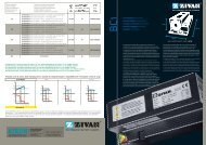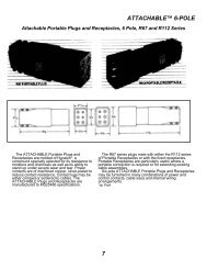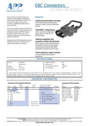
Batteriestecker - Atech Antriebstechnik
Batteriestecker - Atech Antriebstechnik
Batteriestecker - Atech Antriebstechnik

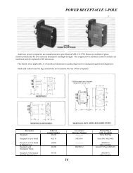
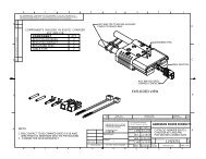
Create successful ePaper yourself
Turn your PDF publications into a flip-book with our unique Google optimized e-Paper software.
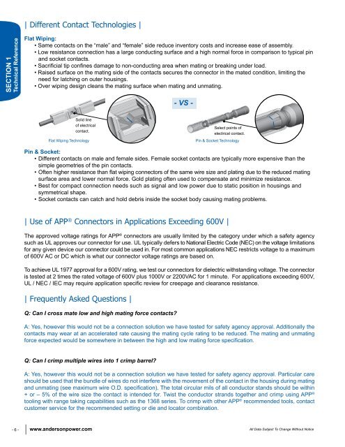
| Different Contact Technologies |<br />
SECTION 1<br />
Technical Reference<br />
Flat Wiping:<br />
• Same contacts on the “male” and “female” side reduce inventory costs and increase ease of assembly.<br />
• Low resistance connection has a large conducting surface and a high normal force in comparison to typical pin<br />
and socket contacts.<br />
• Sacrificial tip confines damage to non-conducting area when mating or breaking under load.<br />
• Raised surface on the mating side of the contacts secures the connector in the mated condition, limiting the<br />
need for latching on outer housings.<br />
• Over wiping design cleans the mating surface when mating and unmating.<br />
- VS -<br />
Solid line<br />
of electrical<br />
contact.<br />
Flat Wiping Technology<br />
Select points of<br />
electrical contact.<br />
Pin & Socket Technology<br />
Pin & Socket:<br />
• Different contacts on male and female sides. Female socket contacts are typically more expensive than the<br />
simple geometries of the pin contacts.<br />
• Often higher resistance than flat wiping connectors of the same wire size and plating due to the reduced mating<br />
surface area and lower normal force. Gold plating often used to compensate and minimize resistance.<br />
• Best for compact connection needs such as signal and low power due to static position in housings and<br />
symmetrical shape.<br />
• Socket contacts can catch and hold debris inside the socket body causing mating problems.<br />
| Use of APP ® Connectors in Applications Exceeding 600V |<br />
The approved voltage ratings for APP ® connectors are usually limited by the category under which a safety agency<br />
such as UL approves our connector for use. UL typically defers to National Electric Code (NEC) on the voltage limitations<br />
for any given device our connector could be used in. For most common applications NEC restricts voltage to a maximum<br />
of 600V AC or DC which is what our connector voltage ratings are based on.<br />
To achieve UL 1977 approval for a 600V rating, we test our connectors for dielectric withstanding voltage. The connector<br />
is tested at 2 times the rated voltage of 600V plus 1000V or 2200VAC for 1 minute. For applications exceeding 600V,<br />
UL / NEC / IEC may require application specific review for creepage and clearance resistance.<br />
| Frequently Asked Questions |<br />
Q: Can I cross mate low and high mating force contacts?<br />
A: Yes, however this would not be a connection solution we have tested for safety agency approval. Additionally the<br />
contacts may wear at an accelerated rate causing the mating cycle rating to be reduced. The mating and unmating<br />
force expected would be somewhere in between the high and low mating force specification.<br />
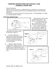
Q: Can I crimp multiple wires into 1 crimp barrel?<br />
A: Yes, however this would not be a connection solution we have tested for safety agency approval. Particular care<br />
should be used that the bundle of wires do not interfere with the movement of the contact in the housing during mating<br />
and unmating (see maximum wire O.D. specification). The total circular mils of all conductor stands should be within<br />
+ or – 5% of the wire size the contact is intended for. Twist the conductor strands together and crimp using APP ®<br />
tooling with range taking capabilities such as the 1368 series. To crimp with other APP ® recommended tools, contact<br />
customer service for the recommended setting or die and locator combination.<br />
- 6 - www.andersonpower.com<br />
All Data Subject To Change Without Notice