Batteriestecker - Atech Antriebstechnik
Batteriestecker - Atech Antriebstechnik
Batteriestecker - Atech Antriebstechnik

You also want an ePaper? Increase the reach of your titles
YUMPU automatically turns print PDFs into web optimized ePapers that Google loves.
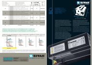
| SB ® 175 CONNECTOR SPECIFICATIONS |<br />
Electrical<br />
Current Rating Amperes¹ UL 1977 CSA<br />
Wire to Wire (1/0 AWG) 280 175<br />
Wire to Busbar (1/0 AWG) 200<br />
Voltage Rating AC/DC<br />
UL 1977 600<br />
Dielectric Withstanding Voltage<br />
Volts AC 2,200<br />
Mechanical<br />
Wire Size Range AWG mm²<br />
Wire Contacts with Bushings 12 to 1/0 3.3 to 53.5<br />
Max. Wire Insulation Diameter in. mm<br />
0.600 15.240<br />
Operating Temperature² °F °C<br />
Standard -4° to 221° -20° to 105°<br />
Chemical Resistant* -40 to 221° -40° to 105°<br />
Avg. Mated Contact Resistance Milliohms¹<br />
6” of 1/0 AWG wire 0.100<br />
Mating Cycles No Load by Plating Silver (Ag)<br />
Wire and Busbar Contacts 10,000<br />
UL Hot Plug Current Rating Amperes - Wire & Busbar<br />
250 cycles at 120V DC 1/0 wire 100A<br />
Materials<br />
Housing<br />
Standard Plastic Resin<br />
Chem. Resistant Resin<br />
Contact Retention Spring<br />
Housing Flammability Rating<br />
UL94 V-0<br />
Polycarbonate<br />
Polycarbonate / PBT blend<br />
Stainless Steel<br />
Avg. Mating / Unmating Force Lbf. N<br />
2 Pole 25 111<br />
3 Pole 35 156<br />
Min. Contact / Spring Retention Force<br />
lbf 150<br />
N 667<br />
Protection<br />
Touch Safety with Wire Contacts<br />
IEC 60529<br />
IP10<br />
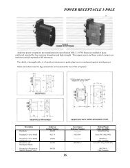
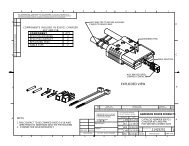
SECTION 3<br />
SB ® 175<br />
Wire & Busbar Contacts<br />
Base<br />
Plating<br />
Contact Termination Methods<br />
Crimp³<br />
Hand Solder<br />
Wrench / Socket<br />
Copper Alloy<br />
Silver<br />
Wire Contacts<br />
Wire Contacts<br />
Busbar Contacts<br />
¹ Based on: 105°C rated or better cable of the largest size, Properly calibrated APP ® recommended tooling, and a<br />
25°C ambient temperature. UL rating not to exceed the maximum operating temperature. CSA rating below a 30°C<br />
temperature rise.<br />
² Limited by the thermal properties of the connector plastic housing.<br />
³ Use APP ® recommended tooling only. Alternate tools may adversely affect the performance of our connectors along<br />
with UL and CSA recognition.<br />
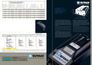
| SB ® 175 CONNECTOR TEMPERATURE CHARTS |<br />
60<br />
SB ® 175<br />
Temperature Rise at Constant Current<br />
125<br />
SB ® 175<br />
Derating vs. Ambient Temperature<br />
50<br />
Temperature (°C)<br />
40<br />
30<br />
20<br />
10<br />
Temperature (°C)<br />
100<br />
75<br />
50<br />
0<br />
0 25 50 75 100 125 150 175 200 225 250<br />
Amperes Applied<br />
1/0 AWG 1 AWG<br />
2 AWG 4 AWG<br />
25<br />
0 25 50 75 100 125 150 175 200 225 250 275 300<br />
Amperes Applied<br />
1/0 AWG 1 AWG<br />
2 AWG 4 AWG<br />
NOTE: Temperature rise charts are based on a 25°C ambient temperature.<br />
- 68 - www.andersonpower.com<br />
All Data Subject To Change Without Notice