Batteriestecker - Atech Antriebstechnik
Batteriestecker - Atech Antriebstechnik
Batteriestecker - Atech Antriebstechnik

You also want an ePaper? Increase the reach of your titles
YUMPU automatically turns print PDFs into web optimized ePapers that Google loves.
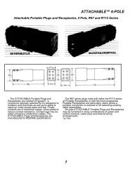
Soldering<br />
The alternative to crimping is to solder all cable strands within the contact barrel. When using an open flame, make sure that you<br />
are not in an area where explosive gasses are present. The right proportion of solder is essential if this procedure is employed.<br />
Use a quality 60/40 solder (60 percent tin, 40 percent lead) in wire form with a rosin flux core. Cable strands should be separately<br />
fluxed with rosin paste, and the contact should be held in a vise with the barrel end facing up. Apply heat to the outside of the<br />
barrel while the solder flows in beside the wire strands.<br />
Here are some things to avoid when soldering:<br />
A. Don’t use too much solder, to the point that it flows out of the contact barrel.<br />
B. Don’t allow flux or solder on the outside of the contact. This will interfere with contact mounting within the installation or<br />
with the contact connection to a mating connector.<br />
C. Don’t overheat and cause excessive solder to “wick” up into the cable and stiffen it. This could interfere with contact<br />
flexibility when connectors are mated.<br />
D. Don’t solder when contact is in the connector housing. Solder away from the housing and then insert the contact into the<br />
housing after it has cooled.<br />
NOTE: Underwriters Laboratories (UL) requires the use of a cable clamp for soldered connections to unsupported wires.<br />
| Determining If A Good Crimp Has Been Made |<br />
1. Assure the correct wire size and type is used for the specific contact being crimped.<br />
2. Follow the assembly instructions for the connector. Special attention should be paid to wire preparation and stripping.<br />
3. Use the correct application tooling as recommended by Anderson Power Products ® (tool, die, & locator).<br />
4. Make several crimps for testing, and record crimp<br />
dimensions in both “x” and “y” planes.<br />
5. Test the electrical resistance across a mated pair<br />
of connectors to the standard of the information<br />
provided on the data sheet.<br />
a. The electrical resistance values should be<br />
similar to (or less than) what we publish for<br />
that connector in our catalogs. Please<br />
see the “Avg. Mated Contact Resistance”<br />
on the data sheet for the specific<br />
connector.<br />
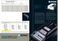
6. Test the pull out strength per the table to the right.<br />
a. To achieve the electrical performance<br />
published in our literature the pull out<br />
values at minimum should meet the UL<br />
486A values for the wire size being used.<br />
The first column (lower value) pull out is the<br />
minimum per UL486A. The second column<br />
is what APP tries to achieve when designing<br />
our crimp solutions. Any force within this<br />
range is acceptable.<br />
7. If crimps are within electrical and mechanical<br />
specifications then the crimp dimensions are suitable<br />
to be used as a secondary inspection criteria.<br />
Lbf<br />
kgf<br />
Wire Size Contact Retention Contact Retention<br />
AWG or MCM Force Range Force Range<br />
22 8 - 12 3.6 - 5.4<br />
20 13 - 16 5.9 - 7.3<br />
18 20 - 30 9.1 - 13.6<br />
16 30 - 40 13.6 - 18.1<br />
14 50 - 60 22.7 - 27.2<br />
12 70 - 85 31.8 - 38.6<br />
10 80 - 125 36.3 - 56.7<br />
8 90 - 180 40.8 - 81.6<br />
6 100 - 200 45.4 - 90.7<br />
4 140 - 280 63.5 - 127<br />
3 160 - 320 72.3 - 145.1<br />
2 180 - 360 81.6 - 163.3<br />
1 200 - 400 90.7 - 181.4<br />
1/0 250 - 500 113.4 - 226.8<br />
2/0 300 - 600 136.1 - 272.2<br />
3/0 350 - 700 158.8 - 317.5<br />
SECTION 4<br />
Tooling<br />
4/0 450 - 775 204.1 - 351.5<br />
250 500 - 800 226.8 - 362.9<br />
300 550 - 800 249.5 - 362.9<br />
All Data Subject To Change Without Notice<br />
www.andersonpower.com - 99 -