EPIC 07 (black door) Owner Manual - The Holland Grill.
EPIC 07 (black door) Owner Manual - The Holland Grill.
EPIC 07 (black door) Owner Manual - The Holland Grill.

You also want an ePaper? Increase the reach of your titles
YUMPU automatically turns print PDFs into web optimized ePapers that Google loves.
READ THIS<br />
BOOK FIRST<br />
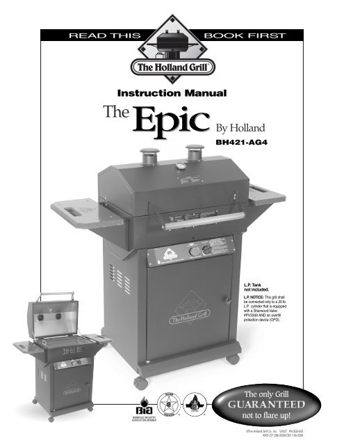
Instruction <strong>Manual</strong><br />
<strong>The</strong><br />
Epic<br />
By <strong>Holland</strong><br />
EpicBH421-AG4<br />
L.P. Tank<br />
not included.<br />
L.P. NOTICE: This grill shall<br />
be connected only to a 20 lb.<br />
L.P. cylinder that is equipped<br />
with a Sherwood Valve<br />
#PV3349 AND an overfill<br />
protection device (OPD).<br />
<strong>The</strong> only <strong>Grill</strong><br />
BARBECUE INDUSTRY<br />
ASSOCIATION MEMBER<br />
TM<br />
TM<br />
not to flare up!<br />
©<strong>The</strong> <strong>Holland</strong> <strong>Grill</strong> Co., Inc. V20<strong>07</strong> PN SG5-002<br />
ANSI Z21.58b-2006/CSA 1.6b-2006
!<br />
DANGER<br />
IF YOU SMELL GAS:<br />
1. SHUT OFF GAS TO APPLIANCE.<br />
2. EXTINGUISH ANY OPEN FLAME.<br />
3. OPEN LID.<br />
4. IF ODOR CONTINUES, KEEP AWAY FROM<br />
THE APPLIANCE AND IMMEDIATELY CALL<br />
YOUR GAS SUPPLIER OR YOUR FIRE<br />
DEPARTMENT.<br />
!<br />
WARNING<br />
1. DO NOT STORE OR USE GASOLINE OR<br />
OTHER FLAMMABLE LIQUIDS OR VAPORS IN<br />
THE VICINITY OF THIS OR ANY OTHER<br />
APPLIANCE.<br />
2. AN LP CYLINDER NOT CONNECTED FOR<br />
USE SHALL NOT BE STORED IN THE VICINITY<br />
OF THIS OR ANY OTHER APPLIANCE.
Cutaway Side View<br />
of your patented <strong>Holland</strong> <strong>Grill</strong><br />
No Flare-up System<br />
Vent Stacks<br />
<strong>The</strong>y provide just the right amount of ventilation<br />
to circulate the heat. Your foods cook evenly<br />
on all sides.<br />
Stainless Steel<br />
Cooking Grid<br />
Stainless steel grid cleans<br />
easily and prevents small<br />
foods from falling through.<br />
Aluminim<br />
Drip Pan<br />
Catches all the drippings<br />
and prevents them from<br />
catching fire.<br />
Flame Deflector<br />
Stainless Steel shield<br />
distrubutes the heat evenly.<br />
Cast Iron Burner<br />
Guaranteed for life!<br />
Simply close the lid and cook by time.<br />
It’s guaranteed not to flare-up.<br />
Thank you for purchasing a <strong>Holland</strong> <strong>Grill</strong>. This is truly a grill that you, your family and friends<br />
will use and enjoy for many years to come.<br />
Many years of research and new technology have gone into the entire line of <strong>Holland</strong> grills,<br />
ensuring they are safe, easy to use and grill to perfection. It’s important that you are aware<br />
that the <strong>Holland</strong> <strong>Grill</strong> is unlike any other grill on the market today. By design, it<br />
allows you to grill, steam or smoke without the worry of flare-ups associated with competitive<br />
brands. Now you can relax while preparing food without the worry and nuisance of trying to<br />
control flames that will ruin your food.<br />
Not only will you be able to enjoy time with friends and family while you grill worry-free, you’ll<br />
be able to do so for years to come. All <strong>Holland</strong> grills are made of top quality materials which<br />
give them a sturdiness that will last for years. We use only the best materials to ensure your<br />
new grill will look like new and cook like new well into the future. This grill was designed and<br />
made for trouble-free out<strong>door</strong> cooking.<br />
Please read and follow all the instructions in this manual.
HOLLAND <strong>EPIC</strong> GRILL OWNERS MANUAL<br />
E-1<br />
Safety Information<br />
Please read carefully.<br />
FOR YOUR SAFETY<br />
• IF YOU SMELL GAS:<br />
1. SHUT OFF GAS TO THE APPLIANCE.<br />
2. EXTINGUISH ANY OPEN FLAME.<br />
3. OPEN LID.<br />
4. IF ODOR CONTINUES, IMMEDIATELY CALL YOUR GAS SUPPLIER<br />
OR FIRE DEPARTMENT.<br />
FOR YOUR SAFETY<br />
1. DO NOT STORE OR USE GASOLINE OR OTHER FLAMMABLE VAPORS<br />
AND LIQUIDS IN THE VICINITY OF THIS OR ANY OTHER APPLIANCE.<br />
2. AN LP CYLINDER NOT CONNECTED FOR USE SHALL NOT BE<br />
STORED IN THE VICINITY OF THIS OR ANY OTHER APPLIANCE.<br />
(A) DO NOT STORE A SPARE LP-GAS CYLINDER UNDER OR NEAR<br />
THIS APPLIANCE;<br />
(B) NEVER FILL THE CYLINDER BEYOND 80 PERCENT FULL; AND<br />
(C) IF THE INFORMATION IN “(A)” AND “(B)” IS NOT<br />
FOLLOWED EXACTLY, A FIRE CAUSING DEATH OR SERIOUS<br />
INJURY MAY OCCUR.<br />
• THIS GRILL IS NOT INTENDED TO BE INSTALLED IN OR ON RECREATIONAL<br />
VEHICLES AND/OR BOATS.<br />
• KEEP OUTDOOR COOKING GAS APPLIANCE AREA CLEAR AND FREE FROM<br />
COMBUSTIBLE MATERIALS, GASOLINE AND OTHER FLAMMABLE VAPORS<br />
AND LIQUIDS<br />
• THIS GRILL SHALL ONLY BE CONNECTED TO AN LP CYLINDER WITH AN OVERFILL<br />
PROTECTION DEVICE (OPD).<br />
• THE GRILL SHOULD BE LIT AND ALLOWED TO OPERATE FOR AT LEAST 30<br />
MINUTES BEFORE USING FOR THE FIRST TIME TO ALLOW PRESERVATIVE TO<br />
BURN OFF. AFTER SMOKE STOPS COMING OUT OF STACKS, GRILL IS READY<br />
FOR YOUR USE AND ENJOYMENT.<br />
• THIS GRILL IS NOT FOR COMMERCIAL USE<br />
• THIS COOKING APPLIANCE IS FOR OUTDOOR USE ONLY AND SHALL NOT BE USED<br />
IN A BUILDING, GARAGE OR ANY OTHER ENCLOSED AREA.<br />
• EXCESSIVELY WINDY OR COLD CONDITIONS MAY AFFECT GRILL COOKING<br />
PERFORMANCE.<br />
• CHOOSE ONLY A LEVEL LOCATION FOR GRILL OPERATION. THE HOLLAND GRILL<br />
MUST BE SITTING SECURELY ON A LEVEL SURFACE FOR PROPER OPERATION<br />
AND EVEN HEAT DISTRIBUTION.<br />
• YOUR GRILL IS MADE FOR OUTDOOR USE ONLY<br />
• THE VENT STACKS AND THE AIR INTAKE OPENINGS SHOULD NEVER BE<br />
BLOCKED OR CLOSED DURING GRILL OPERATION.<br />
• MINIMUM CLEARANCE FROM SIDES AND BACK TO COMBUSTIBLE<br />
CONSTRUCTION, 18 INCHES (50CM) FROM SIDES AND 18 INCHES (50CM) FROM<br />
BACK. IT IS VERY IMPORTANT TO OBSERVE AND MAINTAIN THE PROPER<br />
CLEARANCES FROM COMBUSTIBLE CONSTRUCTION.<br />
• DO NOT USE THIS OUTDOOR APPLIANCE UNDER OVERHEAD COMBUSTIBLE<br />
SURFACES.<br />
• DO NOT STORE A SPARE LP GAS CYLINDER UNDER OR NEAR THIS APPLIANCE.<br />
WARNING: FOLLOW LOCAL CODES<br />
• THE INSTALLATION OF THIS APPLIANCE MUST CONFORM WITH EITHER<br />
THE NATIONAL FUEL GAS CODE ANSI STANDARD REFERENCED WITH<br />
THE FOLLOWING: ANSI Z223.1/ NFPA 54, NATURAL GAS AND PROPANE<br />
INSTALLATION CODE; CSA B149.1, OR PROPANE STORAGE AND<br />
HANDLING CODE, B149.2, OR THE STANDARD FOR RECREATIONAL<br />
VEHICLES, ANSI A 119.2/NFPA 1192, AND CSA Z240 RV SERIES,<br />
RECREATIONAL VEHICLE CODE, AS APPLICABLE”.<br />
• INSTALLATION SHALL BE IN ACCORDANCE WITH CAN/CGAB149.1<br />
NATURAL GAS AND PROPANE INSTALLATION CODE AND LOCAL<br />
CODES WHERE APPLICABLE.<br />
<strong>The</strong> Fuel System<br />
Gas grills are used SAFELY by millions of people when following simple<br />
SAFETY precautions.<br />
<strong>The</strong> items in the fuel system are designed for operation with the<br />
<strong>Holland</strong> <strong>Grill</strong>. <strong>The</strong>y must not be replaced with any other brand.<br />
(See parts list for replacement items.)<br />
GAS BURNER: <strong>The</strong> gas burner is constructed of heavy cast iron and<br />
should not require maintenance other than inspection for insect nests<br />
inside the venturi. If you remove the burner for<br />
cleaning, it must be reinstalled exactly as removed.<br />
AIR SHUTTER: See item 11 in lighting instructions (see figure 6 for<br />
details.)<br />
BURNER VALVE: <strong>The</strong> burner valve is operated in only two<br />
positions. <strong>The</strong> Off position is when the handle is across (perpendicular<br />
to) the burner, which stops the flow of gas. When the valve has been<br />
set in the Off position, it is important to close the valve at the LP gas<br />
cylinder. <strong>The</strong> LP gas cylinder is the primary valve and must be closed<br />
when the grill is not in use. <strong>The</strong> On position is when the handle is in<br />
line with the burner (see figure 6 for details. See lighting instructions<br />
for more information.) <strong>The</strong> burner valve controls the heat allowed in<br />
the grill by means of a plug orifice. This device is set at the factory<br />
and must not be tampered with or replaced. Turn off LP supply at<br />
cylinder when appliance is not in use.<br />
ONLY A FACTORY SUPPLIED VALVE SHOULD BE USED. (See the<br />
parts list for replacement items.)<br />
LP GAS HOSE: <strong>The</strong> LP gas hose is designed for use with LP gas<br />
only. Use with any other gas is dangerous. <strong>The</strong> hose is made of a flexible<br />
material to make it easy to install. This material is subject to considerable<br />
twisting and turning during installation. It is very important<br />
that the hose be inspected for cracks, cuts, abrasions, wear and loose<br />
fittings before each use of the out<strong>door</strong> cooking gas appliance. <strong>The</strong><br />
visual inspection should include leak testing the entire length of hose<br />
and fittings. (See final assembly instructions for more information.)<br />
If the hose shows signs of damage or leakage, it must be replaced<br />
prior to the operation of the grill. Only a factory authorized replacement<br />
part can be used. (See the parts list for replacement items.)<br />
Failure to properly inspect or replace hose with an authorized replacement<br />
may result in accident or injury.<br />
LP GAS REGULATOR: CAUTION: Use only the gas pressure regulator<br />
and hose supplied with this appliance. This regulator and hose is<br />
set for an outlet pressure of 11 inches water column. Substitution of<br />
regulator and hose by any other device or any other manufacturer's<br />
regulator and hose is dangerous and could result in serious injury.<br />
(See the parts list for replacement items.)<br />
IMPORTANT LP CYLINDER INFORMATION: Failure to follow these<br />
DANGER statements exactly may result in a fire causing death or<br />
serious injury.<br />
<strong>The</strong> <strong>Holland</strong> Co. Inc. recommends the use of cylinder manufacturers<br />
Manchester and Worthington, Wolfdale with a 47.6 lb water capacity.<br />
Other cylinders may be acceptable for use with the appliance
GRILL INSTALLER - LEAVE THIS INSTRUCTION BOOKLET FOR THE GRILL OWNER.<br />
GRILL OWNER - SAVE THIS INSTRUCTION BOOKLET FOR FUTURE REFERENCE.<br />
provided they are compatible with the appliance retention means (see<br />
figure 9 on page E6 for retention means point of contact).<br />
PROPANE FUEL: Warning – propane is a flammable gas. Improper handling<br />
may result in an explosion and/or fire and serious accident or injury.<br />
Your grill is designed to operate on Propane (LP) gas ONLY and is<br />
equipped with the proper orifice for this gas. Caution: Do not connect this<br />
grill to any gas supply except propane or natural gas. Propane gas is<br />
heavier than air and will settle in low areas. Make certain adequate ventilation<br />
is available when using your grill and that the gas cylinder is stored<br />
outside in a well ventilated area out of the reach of children when the grill<br />
is not in use.<br />
LP GAS CYLINDER: This grill is designed and intended to be used with<br />
an LP gas cylinder with a nominal LP gas capacity of 20 pounds. Such a<br />
cylinder is approximately 12-3/8" in diameter with an overall height of 18-<br />
1/16". <strong>The</strong> <strong>Holland</strong> <strong>Grill</strong> does not come with an LP gas cylinder. This<br />
must be purchased separately and is available at most hardware stores.<br />
<strong>The</strong> cylinder used must be constructed and marked in accordance with<br />
the specifications for LP gas cylinders of the U.S. Department of<br />
Transportation (DOT) (4BA-240) and the National Standard of Canada<br />
CAN/CSA-B339, Cylinders, Spheres, and Tubes for the transportation of<br />
dangerous goods. Only a cylinder equipped with an overfill protection<br />
device (OPD) should be used.<br />
<strong>The</strong> LP gas cylinder shall be used only out<strong>door</strong>s in a well ventilated<br />
space and not in a building, garage, or any other enclosed area. <strong>The</strong> LP<br />
gas cylinder is designed to be used, stored, and transported in the<br />
upright position. <strong>The</strong> <strong>Holland</strong> <strong>Grill</strong> may be stored in<strong>door</strong>s if the LP gas<br />
cylinder is removed and stored out<strong>door</strong>s. NEVER turn the cylinder<br />
upside down or on its side. Always transport, store and use your cylinder<br />
in the upright position. Cylinders must be stored out<strong>door</strong>s out of the<br />
reach of children and must not be stored in a building, garage or any<br />
other enclosed area.<br />
<strong>The</strong> cylinder must be provided with a Sherwood valve, part #PV3349,<br />
which will connect with (quick connect) the QCC-1 Fitting provided on<br />
each of our LP (propane) grills. Must also have a safety relief device having<br />
a direct communication with the vapor space of the cylinder. <strong>The</strong><br />
cylinder supply system must be mounted vertically for proper vapor withdrawal.<br />
<strong>The</strong> cylinder shall include a collar to protect the cylinder valve.<br />
<strong>The</strong> grill must be connected to the gas supply by a hose. Turn off LP<br />
supply at cylinder when appliance is not in use.<br />
DO NOT transport a full or empty gas cylinder in a closed automobile<br />
trunk or in a closed passenger area.<br />
counter-clockwise.<br />
When disconnecting and connecting the gas cylinder, be careful<br />
that the regulator assembly does not strike the grill, the ground, or<br />
any other surface. If any difficulty at all is had in connecting or disconnecting<br />
the regulator assembly to the cylinder valve, contact<br />
your local gas supplier for assistance.<br />
When disconnected from the cylinder, a valve cap must be installed.<br />
(See figure 1.) Place dust cap on cylinder valve outlet whenever the<br />
cylinder is not in use. Only install the type of dust cap on the cylinder<br />
valve outlet that is provided with the cylinder valve. Other types<br />
of caps or plugs may result in leakage of propane. Failure to install a<br />
valve cap when the cylinder is disconnected from the fuel system is<br />
dangerous and may result in accident or injury.<br />
When re-connecting the LP gas cylinder, be sure to tighten the fitting<br />
until snug. This connection, as well as all other fittings and connections<br />
between the cylinder and burner valve, should be inspected<br />
for damage and leak tested after every filling or<br />
re-connection.<br />
Keep any electrical supply cord and fuel supply hose away from any<br />
heated surface.<br />
NATURAL GAS: If natural gas is used, contact your local supplier<br />
to set it up properly. <strong>The</strong> N.G. <strong>Holland</strong> <strong>Grill</strong> is set to operate at 7<br />
inches water column pressure, using an orifice with a #48 drill size.<br />
If your grill seems too hot, first call your local gas company to determine<br />
what pressure you have.<br />
Never allow anyone to change orifice size without<br />
authorization from factory.<br />
SPARK IGNITER: This grill is equipped with a rotary Piezo igniter<br />
system. A simple Clockwise rotation of the igniter knob produces a<br />
spark at the burner head, lighting the burner. To check that the<br />
spark igniter is working properly, leave gas supply turned OFF and<br />
observe the spark by looking through the peep hole above the control<br />
panel or from below the control panel to the left side of the burner<br />
in the burner opening. A small blue spark should be visible at the<br />
left side of the burner head every time the igniter “fires”. A loud<br />
“hammer” like sound is produced by the mechanism when sparking.<br />
FIGURE 1<br />
COUPLING<br />
NUT<br />
HANDWHEEL<br />
CYLINDER<br />
VALVE<br />
Filling the gas cylinder requires removing it from the grill. <strong>The</strong> cylinder is<br />
attached to the grill by connecting the regulator assembly to the outlet<br />
portion of the gas cylinder valve. This connection is made by the QCC-1<br />
fitting pictured in Figure 1. <strong>The</strong> large plastic nut fits on the outside of the<br />
threads and turns right, or clockwise to tighten. No tools are necessary.<br />
Hand tight is sufficient. If a good connection is not achieved, the safety<br />
valve inside will not permit the proper amount of gas to flow. When connecting<br />
the regulator to the cylinder valve, be sure the pressure relief<br />
valve is directed away from the front and away from the grill. If the relief<br />
valve should open, the propane will be directed where it is likely to do the<br />
least harm. To disconnect regulator assembly turn large plastic nut left or<br />
CONNECT<br />
Clockwise<br />
DISCONNECT,<br />
Counter Clockwise<br />
REGULATOR<br />
CAP &<br />
STRAP<br />
20 LBS<br />
LP GAS CYLINDER<br />
E-2
FIGURE 2b<br />
Cabinet side, RIGHT<br />
Cabinet side, LEFT<br />
FIGURE 3<br />
Cabinet side, RIGHT<br />
8-32 x 3/8 Screw<br />
FIGURE 2a<br />
Insert and fasten Bucket<br />
Bracket into slot as shown<br />
Magnetic Catch<br />
8-32 x 3/8 Hex Nut and Lock Washer<br />
10-24 Phillips head screw<br />
and lock washer<br />
Loosen these 2 bolts.<br />
DO NOT REMOVE COMPLETELY<br />
1/4 - 20 Hex Bolt and<br />
Lock Washer<br />
(typ 8 plcs)<br />
Electrode<br />
Lower Valance<br />
Tank Support<br />
8-32 Phillips head screw<br />
and lock washer<br />
Tank Notches<br />
1/4 - 20 Hex Bolt and<br />
Lock Washer<br />
(typ 4 plcs)<br />
Lower Valance<br />
3/8” Flat Washer<br />
Heavy Duty Caster<br />
ASSEMBLY INSTRUCTIONS<br />
Fasteners Guide<br />
#8-32 x 3/8” Round Head Phillips<br />
#8-32 Lock Washer<br />
#8-32 Hex Nut<br />
❍<br />
Step 1.<br />
On a flat surface (table or carport floor), OPEN AND EMPTY BOTH<br />
BOXES. REFER TO THE CONTENTS LIST TO BE SURE NO PARTS<br />
ARE MISSING. Tighten all factory installed fasteners that may have<br />
loosened during shipping.<br />
#10-24 x 3/8”, #10-24 x 1/2” Round Head Phillips<br />
#10 Lock washer<br />
#10-24 Hex Nut<br />
Step 2.<br />
Refer to Figure 2. Select the following parts for assembly:<br />
1. cabinet side panels (2 ea) 4. tank support brackets (2 ea)<br />
2. lower valance (2 ea) 5. magnetic <strong>door</strong> catch (1ea)<br />
3. casters (4 ea)<br />
❍<br />
Attach magnetic catch to right cabinet side panel as shown in Figure<br />
2a using 2 each 8-32 x 3/8 Phillips screws, nuts and lock washers.<br />
#10-24x1” Carriage Bolt<br />
#10-24x1/2” Carriage Bolt<br />
#10-24 “Top Lock” Hex Nut<br />
❍<br />
Bolt the lower valance (2 ea) to the bottom front/rear of the cabinet side<br />
panels using the 1/4-20 x 5/8” hex head bolts and lock washers as<br />
shown in Figure 2b. Do not fully tighten them at this time.<br />
E-3<br />
1/4 - 20 x 5/8” , 1/4 - 20 x 1” Hex Head Bolt 1/4” Lock washer 1/4” Hex nut<br />
1/4 - 20 x 1” Round Head Phillips<br />
1/4-20 x 1/2” Wing Bolt<br />
(For Tank Hold Down Bracket)<br />
Note: Use one lock washer per bolt, either under the hex nut or under<br />
the bolt head if a hex nut is not used.<br />
❍<br />
❍<br />
Select the tank supports. Place the tank supports inside the cabinet<br />
and attach them to the backside of the lower valance as shown in<br />
Figure 2B. NOTE: <strong>The</strong>y will attach toward the left side of the cabinet. Be<br />
sure the notches in the tank support bracket are up. Secure with 1/4-20<br />
x 5/8” hex head bolts and lock washers. Check to make sure that the<br />
cabinet is square by measuring diagonally, before tightening any bolts.<br />
NOTE: Cabinet must be held square in order for the <strong>door</strong> to open and<br />
close properly. Tighten tank support bolts completely. Now go back and<br />
tighten lower valance bolts completely.<br />
Place one each 3/8” flat washer onto the caster stud. Now screw caster<br />
into the lower valance corners. Tighten securely. Repeat for other 3<br />
corners. NOTE: Locking casters go on the front. Lock the casters to<br />
prevent cabinet from moving around during assembly.
FIGURE 4a<br />
Bottom Assembly<br />
1/4 - 20 Hex Bolt<br />
1/4 Lock Washer<br />
(both sides)<br />
FIGURE 4b<br />
Door Pivot Bracket<br />
Route electrode wire<br />
through obround hole<br />
1/4 - 20 Hex Nut<br />
1/4 Lock Washer<br />
(both sides)<br />
Secure right<br />
side first<br />
10 - 24 x 3/8<br />
Phillips Screw<br />
and Lock Washer<br />
Upper Door<br />
pivot bracket<br />
mounting<br />
location<br />
1/4 - 20 x 1/2<br />
Hex Bolt and<br />
Lock Washer<br />
(both sides)<br />
1/4 - 20 x 5/8” Hex bolt<br />
(both sides)<br />
Knob<br />
Washer / Spacers<br />
Cabinet Assembly<br />
Door Assembly<br />
Cabinet Assembly<br />
❍<br />
❍<br />
❍<br />
❍<br />
Step 3.<br />
Refer to Figure 3. Select the following items:<br />
1. grill bottom assembly<br />
2. bucket bracket<br />
3. electrode<br />
With the grill bottom assembly sitting upright on one end, locate the 1/4<br />
inch diameter hole and slot close to the drain pipe hole. Insert the bucket<br />
hanger bracket in the slot as shown in Figure 3 and secure with 10-<br />
24 x 1/2 Phillips head screw and lock washer. Tighten completely.<br />
Now insert electrode into hole and secure tightly with 8-32 screw and<br />
lock washer. Next, loosen the two 1/4-20 hex bolts shown to prepare for<br />
the next step. DO NOT REMOVE THEM!<br />
Step 4.<br />
Refer to Figure 4a and Figure 4b. Select the following items:<br />
1. grill bottom assembly 5. <strong>door</strong> pivot bracket<br />
2. cabinet assembly 6. <strong>door</strong> knob<br />
3. tank heat shield 7. washer/spacer (2)<br />
4. <strong>door</strong> assembly<br />
Figure 4a Place the grill bottom assembly onto the cabinet base<br />
assembly. Secure the right side only at this time with 1/4-20 x 5/8 hex<br />
head bolts and, lock washers as shown. Do not tighten at this time.<br />
Select the tank heat shield and slide it under the two bolts that you<br />
loosened in the previous step. Be sure the obround cutout aligns with<br />
the electrode and route the electrode wire through it. Lift the other end<br />
of the tank heat shield up to the flange under the grill body as shown.<br />
Now fasten both sides securely with 1/4-20 x 5/8 hex head bolts and<br />
lock washers.<br />
❍<br />
❍<br />
❍<br />
❍<br />
❍<br />
Now bolt upper rear flange of cabinet sides to rear of grill bottom<br />
assembly as shown. Use 1/4-20 x 1/2 hex head bolts and lock washers.<br />
Tighten completely. Repeat for opposite side.<br />
Figure 4b Using a Phillips screwdriver, remove the control panel.<br />
Attach <strong>door</strong> knob to <strong>door</strong> panel using 10-24 x 3/8 Phillips screw and<br />
lock washer as shown.<br />
Select the <strong>door</strong> pivot bracket, washer/spacers and <strong>door</strong> panel assembly.<br />
Slide 2 washer/spacers onto the lower pivot pin of the <strong>door</strong> assembly.<br />
Now insert lower pivot pin with the washer/spacers on it into the<br />
hole in the top surface of the lower valance. Make sure the<br />
washer/spacers do not fall off the pin. Place the <strong>door</strong> pivot bracket onto<br />
the upper <strong>door</strong> pivot pin. Now bolt the <strong>door</strong> pivot bracket to the control<br />
panel bracket as shown using 1/4-20 x 5/8 hex head bolt and lock<br />
washers.<br />
Fasten opposite side of control panel to cabinet side using 1/4-20 x 5/8<br />
hex head bolt and lock washers. Tighten both sides securely.<br />
❍ Re-attach the control panel and plug electrode wire into rotary igniter.<br />
Step 5.<br />
Refer to Figure 5a and Figure 5b. Select the following items:<br />
1. grill lid assembly<br />
2. hinges<br />
3. lid stops (2)<br />
❍<br />
Figure 5a Select one of the lid stops. Insert the end of the lid stop<br />
with the slot in it into the slot in the body bottom end panel. Insert a 10-<br />
24 x 1/2 carriage bolt into the square hole in the bottom end panel.<br />
Make sure the bolt goes inside the slot of lid stop. Secure with flat<br />
E-4
10 - 24 Carriage Bolt<br />
bolt must be inserted<br />
in slot of Lid Stop<br />
FIGURE 5a<br />
Lid Stop<br />
Shelf<br />
1/4 - 20 x 5/8<br />
Hex Bolt and<br />
Lock Washer<br />
Flat Washer and “Top Lock” Nut<br />
Hinge<br />
1/4 - 20 Hex Bolt<br />
and Lock Washer<br />
1/4 - 20 x 1 Round head Phillips<br />
Screw and Lock Washer<br />
FIGURE 5b<br />
10 -24 x 1/2 Carriage Bolt<br />
10 - 24 x 1/2<br />
Carriage Bolt<br />
10 - 24 Top Lock Nut<br />
and flat Washer<br />
10 -24<br />
Hex Nut<br />
and Lock<br />
Washer<br />
<strong>The</strong>rmometer<br />
Hole<br />
FIGURE 7<br />
Insert Lid Stop<br />
into slot in Lid<br />
Lid Stop<br />
cutaways for<br />
clarity only<br />
10 -24<br />
Hex Nut<br />
and Lock<br />
Washer<br />
10 -24 x 1/2 Phillips<br />
Head Screw (8 plcs)<br />
❍<br />
❍<br />
❍<br />
washer and “Top Lock” nut. Tighten the lock nut completely and then<br />
loosen it just enough to allow movement of the lid stop on the screw.<br />
Note: the “Top Lock” nut will be very tight on the screw when installing.<br />
This is normal. Repeat for the opposite side.<br />
Bolt the 2 hinges to the grill bottom assembly using the 1/4-20 x 5/8<br />
hex head bolts and lock washers. Do not fully tighten the hinges at this<br />
time.<br />
Figure 5b Place the lid onto grill bottom assembly. Fasten the body<br />
hinges to the lid assembly using 1/4-20 x 5/8 hex head bolts and lock<br />
washers. Tighten all 8 hinge bolts completely.<br />
Insert a 10-24 x 1/2 carriage bolt into the square hole in the lid end<br />
panel. <strong>The</strong>n while holding the carriage bolt in place, open the lid just<br />
enough to insert the lid stop through the slot in the lid end panel. Place<br />
the single hole in the lid stop over the carriage bolt. Secure with flat<br />
washer and “Top Lock” nut. Repeat for the opposite side. Note: the “Top<br />
Lock” nut will be very tight on the screw when installing. This is normal.<br />
Tighten the lock nut completely and then loosen it just enough to allow<br />
movement of the lid stop on the screw. Repeat for the opposite side.<br />
Step 6.<br />
Refer to Figure 6. Select the following items:<br />
1. shelf brackets (2 lt. 2 rt.)<br />
2. shelves (2 ea.)<br />
❍<br />
❍<br />
❍<br />
❍<br />
❍<br />
Position the shelf onto the brackets as shown. Using 10-24 x 1 carriage<br />
bolts, lock washers and nuts, fasten securely to brackets. Repeat for<br />
opposite side.<br />
Step 7.<br />
Refer to Figure 7. Select the following items:<br />
1. smoke stacks<br />
2. handle and brackets<br />
3. thermometer<br />
Open the lid fully. Using the 10-24 x 1/2 round head Phillips screws,<br />
lock washers and hex nuts fasten the smoke stacks to the grill lid as<br />
shown. Tighten securely.<br />
Install the thermometer through the small hole in the center of the lid<br />
near the smoke stacks. Using a 1/2” wrench, VERY GENTLY, snug<br />
thermometer securing nut. VERY IMPORTANT: DO NOT OVER-<br />
TIGHTEN.<br />
Select the two handle brackets and handle. First attach the brackets to<br />
the lid using 10-24 X 1/2 carriage bolts, lock washers and hex nuts. DO<br />
NOT FULLY TIGHTEN AT THIS TIME.<br />
Now place tube handle between handle brackets and secure with 1/4-<br />
20 X 1” round head Phillips screw and lock washer as shown. Tighten<br />
completely.<br />
❍<br />
Select one of the shelf brackets and bolt it to the grill bottom end<br />
panel using 1/4-20 x 5/8 hex head bolts and lock washers. Tighten<br />
completely. Repeat for each of the 3 remaining brackets.<br />
❍<br />
Now go back and tighten completely the handle brackets to lid<br />
E-5
FIGURE 6<br />
10 -24 x 1” Carriage bolt<br />
Cooking g Grid<br />
Drip Pan<br />
FIGURE 8<br />
Drain Pipe<br />
10 -24 Hex Nut<br />
and Lock Washer<br />
Shelf Bracket<br />
Utensil Hook<br />
Drain Valve<br />
Screws onto drain pipe<br />
Hand tighten only<br />
Drip Bucket<br />
Hangs on Bucket<br />
Bracket<br />
Condiment Tray<br />
Cutaway to<br />
show inside<br />
detail only<br />
❍<br />
❍<br />
❍<br />
Step 8.<br />
Refer to Figure 8. Select the following items:<br />
1. drip pan 4. cooking grid<br />
2. drain pipe 5. drip bucket<br />
3. drain valve<br />
Install the drain pipe into the female threaded coupling in the right end<br />
of the drip pan. Tighten with pliers or pipe wrench.<br />
Carefully set the drip pan into grill bottom using the lift tabs at each<br />
end. Line up the drain pipe with the hole in the grill bottom making sure<br />
pipe extends out bottom and drip pan is setting level in its brackets.<br />
Install the brass drain valve onto the drain pipe. Hand tight only is sufficient.<br />
DO NOT TIGHTEN WITH WRENCH OR PLIERS! (During the<br />
course of maintenance of the grill you will need to remove the drain<br />
valve.)<br />
❍ Now place your cooking grid into the grill.<br />
Step 9.<br />
Refer to Figure 8. Select the following items:<br />
1. condiment tray<br />
2. utensil hooks (3 ea)<br />
❍<br />
❍<br />
Open cabinet <strong>door</strong> and insert utensil hook in upper hole of <strong>door</strong> liner<br />
and rotate downward to allow peg on back side of hook to engage<br />
lower hole. Repeat for other 2 hooks.<br />
<strong>The</strong>n insert tab hooks on condiment tray into slots in <strong>door</strong> liner. Allow to<br />
drop down to lock into position.<br />
❍<br />
❍<br />
❍<br />
Tank Installation<br />
Place your 20-lb. propane tank<br />
into the cabinet base. Make sure<br />
that it is setting securely in the<br />
notches on the tank support<br />
brackets.<br />
Connect the regulator and hose<br />
assembly to the propane tank<br />
valve. This connection is made by<br />
the QCC-1 fitting. <strong>The</strong> large <strong>black</strong><br />
plastic nut fits over the outside of<br />
the tank valve threads and turns<br />
right or clockwise to tighten. No<br />
tools are needed. Hand tight is<br />
sufficient.<br />
If a good connection is not<br />
achieved, the safety valve inside<br />
will not permit the proper amount<br />
of gas to flow.<br />
FIGURE 9<br />
Next attach and adjust downward<br />
the Tank- Hold-Down bracket (see<br />
Figure 9) to secure the tank. Secure with 1/4-20 x 1/2 wing bolt.<br />
Check all bolts and nuts for tightness and then proceed<br />
to leak testing.<br />
Rear View<br />
Tank Hold<br />
down Bracket<br />
1/4 - 20<br />
Wing Bolt<br />
Be sure that<br />
LP tank sets<br />
in notches in<br />
tank supports<br />
E-6
LIGHTING INSTRUCTIONS<br />
SOAPY WATER TEST<br />
In a small bowl mix half liquid detergent and half water. Turn on<br />
propane tank valve. Using a small brush, soap all connections<br />
from tank to grill and look for bubbles. Correct all leaks before<br />
proceeding. Turn off propane tank valve.<br />
NOTE: <strong>The</strong> <strong>Holland</strong> <strong>Grill</strong> uses a 2-position gas valve on the<br />
burner control. <strong>The</strong> left picture under Figure 6 shows the handle<br />
in the OFF position. To turn ON push the handle down and<br />
rotate it counter-clockwise to its full travel (about 90 degrees).<br />
See right picture under Figure 6. NEVER operate the <strong>Holland</strong><br />
<strong>Grill</strong> with the handle in any intermediate position.<br />
FOR NATURAL GAS SUPPLY<br />
<strong>The</strong> <strong>Holland</strong> <strong>Grill</strong>, including the gas off-on valve, must be disconnected<br />
from the gas supply during any pressure testing of<br />
that system, at test pressures in excess of 1/2 psig.<br />
<strong>The</strong> <strong>Holland</strong> <strong>Grill</strong> must be isolated from the gas supply piping<br />
system by closing the individual manual shut-off valve during<br />
any pressure testing of the gas supply piping system at test<br />
pressure equal to or less than 1/2 psig.<br />
FIGURE 6<br />
CUTAWAY VIEW<br />
Refer to Figure 6.<br />
1. Make sure the propane tank valve and the burner valve are<br />
both fully off.<br />
2. Open the grill lid and allow five full minutes to air out.<br />
3. BEFORE EACH USE, inspect the gas system of the out<strong>door</strong> cooking<br />
device for damaged hose or loose fittings. Check the hose for<br />
wear, abrasions, cuts or kinks. If any damage is found, replace<br />
hose and regulator using only factory-approved replacement hose<br />
and regulator. Never attempt to light this or any gas grill with a<br />
cracked, split, braided, or severely kinked hose or with any broken<br />
or leaking fittings.<br />
SPARK IGNITER LIGHTING<br />
4. With the grill lid opened, slowly open valve at propane tank or<br />
natural gas supply.<br />
5. Turn the red knob on the gas valve 90 degrees counter-clockwise<br />
to the ON position.<br />
6. IMMEDIATELY TURN THE SPARK IGNITER KNOB<br />
CLOCKWISE RAPIDLY UP TO 5 TIMES<br />
7. If ignition does not occur in 5 seconds, turn the burner control(s)<br />
off, wait 5 minutes, and repeat the lighting procedure.<br />
MANUAL MATCH LIGHTING<br />
8. With the grill lid opened, slowly open valve at propane tank or natural<br />
gas supply. Insert lit match or lighter into left side of burner hole<br />
opening, next to burner, up under control panel with flame next to<br />
burner head.<br />
9. Turn the red knob on the gas valve 90 degrees counter-clockwise<br />
to the ON position. If ignition does not occur in 5 seconds, turn the<br />
burner control(s) off, wait 5 minutes, and repeat lighting procedure.<br />
10. When the burner lights remove the match or lighter.<br />
Lock Nut<br />
<strong>Manual</strong>/Match Lighting<br />
Hole<br />
Air shutter<br />
& lock nut<br />
Gas valve<br />
Air Shutter<br />
Insect Screen<br />
Cast iron<br />
Burner<br />
ADJUSTING AIR SHUTTER<br />
11. Loosen the lock nut with an 5/8” open end wrench, so you can<br />
turn. Adjust the flame by turning the air shutter on the face of the<br />
burner valve slowly. When most of the orange color has left the<br />
flame, and it has become uniformly pale yellow-to-blue, the flame<br />
is properly set. <strong>The</strong>re should be no need for re-adjustment for the<br />
life of your <strong>Holland</strong> <strong>Grill</strong>, but it is wise to check the flame color each<br />
time you light your grill. When proper setting is obtained be sure to<br />
re-tighten the lock nut against the valve.<br />
Red<br />
Gas control knob<br />
Gas<br />
supply hose<br />
Make sure while looking to adjust or check flame to use the peep hole<br />
just above valve. See below: <strong>The</strong> flame should be blue in color.<br />
NOTE: Some yellow tipping may occur. It’s not unusual and will not<br />
affect the performance of the grill.<br />
Closed (OFF)<br />
Open/Light (ON)<br />
Gas Valve & Hose Connection Detail<br />
PROPER AIR SHUTTER SETTING<br />
E-7<br />
Complete Gas System<br />
regulator, hose, on/off valve and cast iron burner<br />
12. After air shutter adjustment, your grill is ready for use – proceed to<br />
COOKING INSTRUCTIONS.<br />
13. If the burner did not light properly, wait 5 minutes before attempting<br />
to relight, then repeat steps 1-9<br />
14.If the grill fails to light after the second attempt, call your local LP<br />
gas dealer for professional assistance.
15. With the burner lit, gently close the lid and allow the grill to warm<br />
for 20-30 minutes.<br />
NOTE: If for any reason the burner should go out, shut off gas at the<br />
burner and the LP cylinder. DO NOT attempt to re-light without<br />
repeating steps 2-10.<br />
TURNING GRILL OFF<br />
1. Open lid<br />
2. Turn burner valve OFF<br />
3. Turn off LP supply at cylinder when appliance is not in use.<br />
4. CAUTION: Do not attempt to relight without following all<br />
lighting instructions.<br />
IMPORTANT: Always shut off the burner valve before closing the<br />
tank/gas supply valve. This grill is equipped with a QCC-1 flow-limiting<br />
connector which will not reset to allow full gas flow if the supply valve<br />
is closed before the burner valve is shut off. If you experience trouble<br />
with the grill not heating properly, shut off burner valve, then tank or<br />
supply valve. Open lid, wait 5 minutes and follow lighting instructions.<br />
CARE AND MAINTENANCE<br />
<strong>The</strong>re is very little care and maintenance needed. <strong>The</strong> <strong>Holland</strong> <strong>Grill</strong> is<br />
designed and made of materials that will last many years with normal<br />
use. Following these instructions will improve the longevity and quality<br />
of cooking. To assure safe operation of your <strong>Holland</strong> <strong>Grill</strong>, the area for<br />
cooking should always be kept free of combustible materials of any<br />
type, such as gasoline or other flammable vapors or liquids.<br />
Outside of body: This is aluminum metal. It can be cleaned<br />
easily with warm, soapy water or mild cleaner. If paint gets scratched,<br />
remove grease and repaint with a heat resistant paint. <strong>The</strong> metal<br />
surface will last longer. Do not use wire brushes, scrapers or abrasive<br />
cleaners for normal cleaning.<br />
Grid and Drip Pan: <strong>The</strong> grid is made of high quality stainless steel.<br />
<strong>The</strong> grid should be brushed with a brass, copper, or stainless steel<br />
brush immediately after removing food while grill is still warm. <strong>The</strong> drip<br />
pan is aluminum and can be cleaned with a flat scraper such as a<br />
putty knife. CAUTION: <strong>The</strong> drip pan must be kept clean and free of<br />
heavy build-up for grill to perform properly, and to eliminate flare-ups.<br />
Do not wash drip pan.<br />
Inside <strong>Grill</strong>: Use warm soapy water to clean this area. Do not allow<br />
grease to build up.<br />
Drain Pipe and Valve: Both must be kept clear of grease and food<br />
particles to allow grease to drain properly from drip pan. This must be<br />
done to maintain proper operation of your grill.<br />
Food Boards: <strong>The</strong>se are made from high density polyethylene,<br />
approved by the FDA for direct food contact. Warm soapy water can<br />
be used for cleaning. CAUTION: It should not be used as a chopping<br />
block, nor should more than 15 pounds be placed on it at any time.<br />
• Check to be sure all openings into the grill body are free of<br />
blockages or debris. Make sure there are no objects or materials<br />
blocking the flow of combustion and ventilation air.<br />
• Turn off LP supply at cylinder when appliance is not in use.<br />
• For out<strong>door</strong> use only. If stored in<strong>door</strong>s, detach cylinder and leave<br />
it out<strong>door</strong>s.<br />
• Cylinders must be stored out<strong>door</strong>s out of reach of children and<br />
must not be stored in a building, garage or any other enclosed<br />
area.<br />
• Check burner venturi behind air shutter screen for insect nests<br />
or blockages. Make sure the passage through the burner venturi<br />
is not obstructed. A clogged tube can lead to a fire beneath the grill.<br />
• Keep the ventilation opening(s) of the cylinder enclosure free and<br />
clear from debris<br />
Location of the valve to the Burner: If the burner valve is ever<br />
removed for cleaning or replacement, it should be re-installed to the<br />
dimension shown below. Measure from the center of the valve inlet to<br />
the face of the burner air shutter. This assures correct positioning of<br />
the orifice in the burner venturi.<br />
1"<br />
IMPORTANT - FIRST TIME USE: It is important that the grill be lit<br />
and allowed to operate at least 30 minutes before any food is placed<br />
on the grill grid. Some smoke may appear during this period. This is<br />
the preservative used during manufacturing. After initial heating, the<br />
grill is ready for use. After burning off the grill, spray the food grid, drip<br />
pan and the inside of the lid with PAM or similar spray, so food does<br />
not stick to the grid and the inside is easier to clean.<br />
MOVING INSTRUCTIONS<br />
CAUTION: NEVER MOVE GRILL WITH BURNER LIT OR WITH<br />
WATER IN DRIP PAN.<br />
Moving in your yard or deck: Make sure gas is turned off at<br />
burner valve and tank valve. Be sure lid is closed. Unlock casters and<br />
push to desired location, first checking for holes or obstacles that may<br />
cause tripping or falling. Re-lock casters after moving.<br />
Moving on trailer or truck: Follow all steps above. Before loading,<br />
secure lid closed. After loading, be sure to tie down securely to<br />
prevent damage.<br />
NEVER transport your grill with propane tank connected.<br />
CAUTION: Always secure propane tank tightly to truck or trailer.<br />
General: This grill, like all equipment, will look better and last longer<br />
if kept out of weather when not in use. CAUTION: Do not store gas<br />
tank in closed areas. See instructions or local gas ordinances for care<br />
and storage of propane tanks. When using a cover, never place it on<br />
the grill until the entire unit has cooled at least 30 minutes.<br />
E-8
COOKING INSTRUCTIONS<br />
ALLOW GRILL TO WARM UP WITH LID CLOSED FOR 20 - 30<br />
MINUTES PRIOR TO COOKING.<br />
• It is important to realize cooking on a <strong>Holland</strong> <strong>Grill</strong> uses a different<br />
process in order for the grill to perform correctly. It is essential that<br />
the lid remain closed while grilling.<br />
NOTE: Check drip pan valve to make sure it is completely<br />
open while grilling<br />
• IF YOU'RE LOOKING, YOU'RE NOT COOKING!<br />
Since this grill uses a combination of direct and indirect heat, the lid<br />
must be closed at all times.<br />
• <strong>The</strong> <strong>Holland</strong> <strong>Grill</strong> has no temperature controls. This means the<br />
temperature remains constant; it’s simply a matter of timing. Refer<br />
to most any cookbook for the cooking time of an item cooked at the<br />
recommended 400 degree temperature. Remember, you will<br />
probably want to turn the food over once at approximately half the<br />
cooking time on short cooking time items.<br />
• <strong>The</strong> cooking times we suggest are only that – suggestions.You<br />
may want to vary the times as you become familiar with your<br />
<strong>Holland</strong> <strong>Grill</strong>.<br />
• You may cook on the grill in any weather. If the temperature is<br />
extremely hot or cold, it will slightly shorten or increase your<br />
cooking time.<br />
GRILLING<br />
Steak -- T-Bone: 1" thick, Medium doneness: <strong>Grill</strong> 10 minutes on<br />
each side.<br />
Chicken, Quarters, average size fryer: Cook skin side up for<br />
30 minutes and skin side down for 30 minutes. Check for doneness. If<br />
chicken is completely done, only then, dip or brush on the sauce of<br />
your choice. Put back on the grill for approximately 10 minutes longer.<br />
NOTE: You may want to repeat this process one or two more times.<br />
Pork ribs and chops, 3/4" thick: <strong>Grill</strong> 10 to 20 minutes on each<br />
side. When done, either dip or brush on sauce. Put back on the grill for<br />
5 to 10 minutes longer. Repeat if desired.<br />
SEE PAGE E-11 FOR MORE COOKING IDEAS<br />
DRY SMOKING<br />
Place Flav-O-Buds or chunks of<br />
your favorite dry wood in the aluminum<br />
bud tray provided. Place it<br />
in one of the rear corners in the<br />
space between the top edge of<br />
the drip pan and the bottom edge<br />
of the flange under the cooking<br />
grid (see picture at right).If additional<br />
wood is preferred, you can<br />
use throw-away aluminum tart<br />
pans in the rear corners of the dry<br />
drip pan.<br />
Each bud tray or tart pan can be placed in one or both corners in the<br />
space between the top edge of the drip pan and the flange, and the<br />
bottom of grill. Refer to picture at right.<br />
Each pan will smoke up to an hour, depending on how many chips or<br />
chunks you use in each pan. When finished grilling, throw away wood<br />
and use fresh each time you grill.<br />
STEAMING<br />
To steam foods such as oysters, clams, shrimp, crab legs, etc., follow<br />
these procedures:<br />
1. Move the grill to location you plan to use it for steaming.<br />
<strong>The</strong> grill should be level.<br />
2. Close the drain valve.<br />
3. Following lighting instructions, light the grill and preheat it for 30<br />
minutes, then add 1 gallon hot water to the drip pan.<br />
4. Close lid. In 20-30 minutes, you should see and feel steam<br />
coming from the stack.You are ready to begin the steaming<br />
process.<br />
5. Put food you wish to steam on grill and close lid. Most shellfish<br />
will cook in 15 to 25 minutes.You may want to cook yours<br />
less or more time after checking.<br />
NOTE: Liquid smoke, beer or seasonings such as Brad’s Private<br />
Stock Seasoning Mix can be added to the hot water to get some<br />
seasoning effect.<br />
CAUTION: Do not drain water from the grill until it has cooled for<br />
at least 30 minutes.<br />
Drain water from pan by placing a large bucket directly under the drain<br />
pipe. Open the valve being careful to keep hands away from the water<br />
flow.Your grill is now ready to resume regular grilling<br />
procedures.<br />
E-9
HOLLAND <strong>EPIC</strong> GRILL REPLACEMENT PARTS<br />
Model BH421-AG4<br />
<strong>The</strong> <strong>Holland</strong> Epic parts are made from quality stainless<br />
steel, aluminum and aluminized metal<br />
with a quality powder<br />
coat finish.<br />
REPLACEMENTS PARTS LIST<br />
Stock No. Description<br />
Stock No. Description Fasteners.<br />
AG4-100W-WELD BODY BOTTOM ASSEMBLY<br />
AG4-200W-WELD BODY TOP ASSEMBLY<br />
AG4-702<br />
SHELF BRACKET LF/RR<br />
AG4-703<br />
SHELF BRACKET LR/RF<br />
SG4-701<br />
SHELF, GRAY GRANITE<br />
AG4-170C-WELD CONTROL PANEL MTG BRKT<br />
AG4-155C<br />
CONTROL PANEL<br />
AG4-302C-WELD LOWER VALANCE WELD ASSEMBLY<br />
AG4-251R<br />
HANDLE BRACKET, RIGHT<br />
AG4-251L<br />
HANDLE BRACKET, LEFT<br />
AG4-250<br />
HANDLE TUBE ASSEMBLY, ALUM.<br />
AG4-300C-WELD CABINET SIDE PANEL, RIGHT<br />
AG4-301C-WELD CABINET SIDE PANEL, LEFT<br />
AG4-3<strong>07</strong>C<br />
MAGNETIC CATCH<br />
SG2-301<br />
SMOKE STACK, BLACK<br />
AG2-600<br />
DRIP PAN WELD ASSEMBLY<br />
SG4-910 DRAIN PIPE 3/4"<br />
SG4-909<br />
DRAIN VALVE, LEVER HANDLE,3/4"<br />
AG2-120<br />
DRIP PAN BRACKET<br />
AG2-106<br />
AIR BAFFLE WELD ASSEMBLY<br />
AG2-300<br />
COOKING GRID<br />
AG4-511<br />
CASTER, SWIVEL LOCKING<br />
AG4-512<br />
CASTER, SWIVEL NON-LOCKING<br />
SG2-531<br />
LIGHTING CLIP AND CHAIN<br />
SG2-1000<br />
DRIP BUCKET<br />
SS5-303C<br />
BUCKET HANGER BRACKET<br />
AG4-801C-WELD TANK RETAINER<br />
AG4-555C<br />
TANK SUPPORT<br />
SS5-914C<br />
LID STOP<br />
SG2-101<br />
HINGE, BLACK<br />
SG4-280<br />
THERMOMETER<br />
SG2-105<br />
CAST IRON BURNER<br />
AG2-1<strong>07</strong><br />
FLAME DEFLECTOR<br />
SG4-750<br />
ROTARY PIEZO IGNITER<br />
SG4-751<br />
ELECTRODE<br />
SG4-752<br />
IGNITER KNOB<br />
SG4-150<br />
KNOB, GAS VALVE, HOLLAND<br />
SG4-102<br />
GAS VALVE, ANGLED<br />
SG2-811<br />
GAS VALVE JAM NUT<br />
SG2-103<br />
AIR SHUTTER<br />
SG2-104<br />
INSECT SCREEN<br />
SG2-111-55 PROPANE GAS ORIFICE #55<br />
SG2-111-48 NATURAL GAS ORIFICE #48<br />
SG2-109<br />
HOSE AND REGULATOR ASSEMBLY<br />
AG4-160C<br />
TANK HEAT SHIELD<br />
AG4-308C<br />
UTENSIL HOOK<br />
AG4-304C<br />
CONDIMENT TRAY<br />
AG4-305C-ASSY DOOR PANEL ASSEMBLY<br />
AG4-310C<br />
DOOR KNOB<br />
AG4-309C<br />
DOOR PIVOT BRACKET<br />
LWP-001BL<br />
CAUTION PLATE, LID<br />
SG4-002A<br />
CLEARANCES/INFO STICKER<br />
AG4-1014<br />
HARDWARE BAG<br />
AG4-312C<br />
NYLON WASHER, BLACK 1/8" THICK<br />
AG4-MAN<br />
OWNER'S MANUAL<br />
WARRANTY CARD<br />
1. 8-32 X 3/8” Round Head Phillips Screw, S/S<br />
2. 8-32 Hex Nut, S/S<br />
3. #8 External Tooth Lock Washer, S/S<br />
4. 10-24 x 1/2” Round Head Phillips Screw, S/S<br />
5. 10-24 x 1/2” Carriage Bolt, S/S<br />
6. 10-24 x 1” Carriage Bolt, S/S<br />
7. 10-24 Hex Nut, S/S<br />
8. 10-24 Top Lock Hex Nut, S/S<br />
9. #10 External Tooth Lock Washer, S/S<br />
10. #10 Flat Washer, S/S<br />
11. 1/4-20 x 5/8” Hex Head Bolt, S/S<br />
12. 1/4-20 x 1” Hex Head Bolt, S/S<br />
13. 1/4-20 x 1” Round Head Phillips Screw, S/S<br />
14. 1/4-20 Hex Nut, S/S<br />
15. 1/4” External Tooth Lock Washer, S/S<br />
16. 1/4-20 x 1/2” Wing Bolt, S/S<br />
17. 3/8” Flat Washer, S/S<br />
18. Nylon Washer (Door Pivot)<br />
If you have a question about the warranty or want to order parts or accessories, please contact your local <strong>Holland</strong> <strong>Grill</strong><br />
dealer or call 800-880-9766 or visit us on the web at hollandgrill.com<br />
E-10
HOLLAND GRILLING TIME CHART<br />
<strong>Grill</strong>ing<br />
Chicken 3 lb. quartered or halves 40-60 minutes total grilling time<br />
Chicken legs or thighs<br />
45 minutes<br />
Pork Chops 1 inch thick 15 minutes each side<br />
Steak 3/4 - 1 inch thick 9 minutes each side<br />
italian Sausage<br />
40 minutes<br />
Pork Sausage Patty 8 minutes each side<br />
Pork Ribs<br />
45 minutes<br />
Hamburger Patty 9 minutes each side<br />
Prime Rib<br />
2 - 2 1/2 hours -- use meat thermometer<br />
Pork Roast<br />
Use meat thermometer<br />
Vegetables All 30-45 minutes total cooking time -- best in covered dish<br />
Biscuits Canned 9 minutes one side & 5 minutes other side<br />
Smoking<br />
Turkey<br />
Fish<br />
Steaming<br />
Oysters, clams,<br />
crab legs, etc.<br />
15 minutes per pound<br />
20 minutes total<br />
Approximately 20 minutes<br />
NOTE: Remember, the <strong>Holland</strong> <strong>Grill</strong> needs to warm up completely. Temperature will remain about 400 degrees F.<br />
All grilling times are approximate depending on size, weight and individual taste preference. <strong>Grill</strong> needs to remain<br />
closed at all times during grilling to be accurate with this time chart. Each time grill is opened during the grilling process,<br />
increase grilling time by approximately 10 minutes. A time chart in any cookbook may be of some assistance.<br />
GRILLING INSTRUCTIONS<br />
Fish <strong>Grill</strong>ing: Allow grill to warm up for 15 minutes. Place fish on grill<br />
and season to taste. Allow 20-30 minutes total grilling time, turning at<br />
half the grilling time if desired (turning is not necessary).<br />
Fish Smoking: Make sure grill is where you intend to use it. Close<br />
valve on drip pan, and fill with 1 gallon water (hot water speeds up<br />
process). Add liquid smoke to water and sprinkle small amount on fish.<br />
Light grill.You will feel steam on top of stacks in about 15 minutes, then<br />
place fish on grill for approximately 20 minutes. Add seasonings at any<br />
time.<br />
Shellfish: (oysters, clams, crab legs, etc.): Same as fish smoking,<br />
allow 15-30 minutes grilling time.<br />
Turkey Bar-B-Que: Allow 15 minutes warm up time. Place turkey<br />
on its back in center of grill. Allow 15 minutes grilling time per pound.<br />
Not necessary to turn.<br />
Chicken Halves or Quarters: Place on grill for 60 minutes.<br />
Turn at 30 minutes if desired.<br />
Steak 3/4” - 1” thick: Allow grill to warm for 15 minutes, then<br />
place steaks on grill. Allow 6-10 minutes per side. Ten minutes on<br />
each side will produce medium well to well done steaks.<br />
Hamburger: Same as steak.<br />
Ribs: Allow grill to warm for 15 minutes, place ribs on grill. Allow<br />
40-60 minutes grilling time. Turn at half the grilling time if desired<br />
(not necessary). Baste or dip in sauce at any time.<br />
Roast (pork, beef, lamb, etc.): Place in center of grill. Pans or<br />
aluminum foil are not necessary. Allow 20 minutes per pound grilling<br />
time. Use meat thermometer.<br />
Turkey Smoked: Follow same procedure as smoking fish. <strong>Grill</strong> 15<br />
minutes per pound and use meat thermometer to test for doneness.<br />
E-11
<strong>EPIC</strong> GRILL GAS CONVERSION KIT INSTRUCTIONS<br />
SG5-LABEL-LP GAS CONVERSION KIT INSTRUCTIONS <strong>EPIC</strong> MODELS<br />
Natural Gas to LP (propane) Gas<br />
Apply included sticker to unit after converting.<br />
STEP 1 Close valve at gas supply.<br />
STEP 2 At the grill, remove on/off knob from gas valve.<br />
STEP 3 Remove the control panel by removing the Phillips head screws.<br />
STEP 4 Using 2 wrenches, loosen and remove the supply line from the gas valve inlet.<br />
STEP 5 Using a wrench, loosen air shutter jam nut by turning counter-clockwise.<br />
STEP 6 Remove gas valve from burner by turning counter-clockwise.<br />
STEP 7 Remove the No. 48 orifice from gas valve. It is the hex shaped fitting located in the end that was screwed into the burner.<br />
STEP 8 Replace the No. 48 Natural gas orifice with the No. 55 LP (propane) gas orifice. Installation is the reverse.<br />
STEP 9 Use only a <strong>Holland</strong> <strong>Grill</strong> factory authorized LP (propane) hose and regulator assembly.<br />
STEP 10 Attach the regulator hose to the gas valve inlet and then attach big <strong>black</strong> plastic nut to LP tank.<br />
NOTE: Be sure to properly adjust the air shutter before tightening the jam nut.<br />
WARNING: After installation is complete check for leaks using a soapy water solution. Tighten fittings as necessary to correct.<br />
NEVER OPERATE THIS APPLIANCE OR ANY OTHER APPLIANCE WITH A GAS LEAK. SERIOUS INJURY OR DEATH MAY OCCUR!<br />
SG5-LABEL-NAT GAS CONVERSION KIT INSTRUCTIONS <strong>EPIC</strong> MODELS<br />
LP (propane) Gas to Natural Gas<br />
Apply included sticker to unit after converting.<br />
STEP 1 Close valve on LP (propane) tank.<br />
STEP 2 Disconnect and remove the regulator and hose assembly from the LP (propane) tank by<br />
unscrewing counter-clockwise the large <strong>black</strong> plastic nut.<br />
STEP 3 At the grill, remove on/off knob from gas valve.<br />
STEP 4 Remove the control panel by removing the Phillips head screws.<br />
STEP 5 Using 2 wrenches, loosen and remove the regulator hose from the gas valve inlet. Save for possible future use.<br />
STEP 6 Using a wrench, loosen air shutter jam nut by turning counter-clockwise.<br />
STEP 7 Remove gas valve from burner by turning counter-clockwise.<br />
STEP 8 Remove the No. 55 LP (propane) gas orifice from gas valve. It is the hex shaped fitting located in the end that was screwed into the burner.<br />
STEP 9 Replace the No. 55 LP (propane) gas orifice with the No. 48 Natural gas orifice. Installation is the reverse.<br />
NOTE: Be sure to properly adjust the air shutter before tightening the jam nut. Place conversion sticker in highly visible location.<br />
WARNING: After installation is complete check for leaks using a soapy water solution. Tighten fittings as necessary to correct. NEVER OPERATE THIS<br />
APPLIANCE OR ANY OTHER APPLIANCE WITH A GAS LEAK. SERIOUS INJURY OR DEATH MAY OCCUR!
<strong>The</strong> <strong>Holland</strong> <strong>Grill</strong> Company, Inc.<br />
121 Thomas Mill Road Holly Springs, NC 27540<br />
Call 1-800-880-9766 or visit www.hollandgrill.com for a dealer near you.<br />
©<strong>The</strong> <strong>Holland</strong> <strong>Grill</strong> Co., Inc. V20<strong>07</strong>