OR-T 200 04.05.indd - Acme Packaging
OR-T 200 04.05.indd - Acme Packaging
OR-T 200 04.05.indd - Acme Packaging

You also want an ePaper? Increase the reach of your titles
YUMPU automatically turns print PDFs into web optimized ePapers that Google loves.
DEUTSCH 3<br />
ENGLISH 14<br />
FRANÇAIS 25<br />
ITALIANO 36<br />
BETRIEBSANLEITUNG UND SICHERHEITSV<strong>OR</strong>SCHRIFTEN<br />
OPERATING AND SAFETY INSTRUCTIONS<br />
MODE D‘EMPLOI ET DE SÉCURITÉ<br />
ISTRUZIONI PER L‘USO E DI SICUREZZA<br />
<strong>OR</strong>-T <strong>200</strong><br />
Ab Serie-Nr. 2/49<strong>200</strong><br />
From serie no 2/49<strong>200</strong><br />
A partir du no de série 2/49<strong>200</strong><br />
A partire dal no di serie 2/49<strong>200</strong><br />
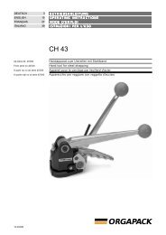
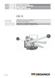
Akku-Handgerät zum Umreifen mit Kunststoffband<br />
Battery-hand tool for plastic strapping<br />
Appareil sur accu pour le cerclage par bande plastique<br />
Apparecchio da batteria per reggiare con reggetta di plastica<br />
Vor dem Gebrauch des<br />
Gerätes die Betriebsanleitung<br />
aufmerksam<br />
lesen.<br />
Before using the tool,<br />
read the operating<br />
instructions carefully.<br />
Avant l’utilisation de<br />
l’appareil, consultez<br />
soigneusement le<br />
mode d’emploi.<br />
Prima d’utilizzare<br />
l’apparecchio, leggere<br />
attentamante le istruzioni<br />
per l’uso.<br />
04.05/WE
<strong>OR</strong>GAPACK <strong>OR</strong>-T <strong>200</strong><br />
TABLE OF CONTENTS<br />
Page<br />
1 Technical data 14<br />
2 General information 15<br />
2.1 Information on environmental protection 15<br />
3 Safety instructions 16<br />
3.1 Safety instructions for battery<br />
charger and battery 16<br />
4 Description 17<br />
4.1 Construction 17<br />
4.2 Operating panel 17<br />
4.3 Function 17<br />
4.4 Battery charger indicators 18<br />
5 Initial operation 19<br />
5.1 Battery charger 19<br />
5 .2 First battery charge 19<br />
5.3 Charging the battery 19<br />
6 Operating instructions 20<br />
6.1 Operating the tool 20<br />
6.2 Checking the seal 21<br />
6.3 Operating panel 22<br />
6.3.1 Checking battery charge 22<br />
6.3.2 Setting strap tension 22<br />
6.3.3 Setting welding time 22<br />
6.3.4 Setting strap tension range 23<br />
6.4 Setting strap width 23<br />
7 Preventive and corrective maintenance 24<br />
7.1 Cleaning/replacing tension wheel 24<br />
7.2 Cleaning/replacing tooth plate 24<br />
7.3 Replacing cutting knife 24<br />
8 Recommended spare parts 47<br />
8.1 Parts list 47<br />
Exploded drawing 53<br />
1 TECHNICAL DATA<br />
Weight<br />
3.9 kg (8.6 lbs) (incl. battery)<br />
Dimensions Length 375 mm (14.7“)<br />
Width 130 mm (5.1“)<br />
Height 140 mm (5.5“)<br />
Strap tension<br />
400–<strong>200</strong>0 N<br />
Tension speed 260 mm/s (10.2“/s)<br />
Sealing<br />
Friction welded<br />
Emission sound pressure<br />
levels, measurement<br />
type A (EN ISO 11202) L pA<br />
82 dB (A)<br />
Vibrations at handle<br />
(EN ISO 8662-1) a h,w<br />
2.2 ms -2<br />
BATTERY CHARGER / BATTERY<br />
Voltage<br />
Charging time<br />
Strappings with<br />
one battery charge<br />
Service life<br />
PLASTIC STRAP<br />
Battery charger, 100/240 V<br />
(AL 60 DV 1419)<br />
Bosch 12 V / 2.4 Ah / NiCd<br />
60 minutes<br />
100 to <strong>200</strong> depending on<br />
strap, strap tension and<br />
package<br />
Up to approx <strong>200</strong>0 chargings<br />
Strap quality Polypropylene (PP)<br />
Polyester (PET)<br />
Strap width<br />
adjustable to 12–13, 15–16 mm ( 1 / 2<br />
“, 5 / 8<br />
“)<br />
Strap thickness<br />
Polypropylene 0.6–1.0 mm<br />
(.023“–.039“)<br />
Polyester 0.5–1.0 mm<br />
(.019“–.039“)<br />
DECLARATION OF AGREEMENT<br />
We take sole responsibility for declaring that the<br />
tool <strong>OR</strong>-T <strong>200</strong>, to which this declaration refers, is<br />
in full compliance with the current requirements of<br />
the guidelines laid down by the council on 22th<br />
June 1998 (98/37/EEC), “Machine Guidelines“.<br />
Furthermore, electrical installations are in compliance<br />
with the guideline laid down by the council on<br />
3th May 1989 (89/336/EEC) “EMV Guidelines“.<br />
EN 1050, EN 50082-2, IEC 61000-6-2, EN 55022,<br />
EN 50081-1<br />
CH-8953 Dietikon, June <strong>200</strong>4<br />
Manager<br />
Sales & Marketing:<br />
Manager<br />
Engineering:<br />
According to norm:<br />
R. Kieffer M. Binder<br />
EN ISO 12100-1, EN ISO 12100-2, EN 349,<br />
14 04.05/WE
<strong>OR</strong>GAPACK <strong>OR</strong>-T <strong>200</strong><br />
2 GENERAL INF<strong>OR</strong>MATION<br />
These operating instructions are intended to simplify<br />
familiarisation with the strapping tool and its proper<br />
use for the intended purpose. The operating instructions<br />
contain important information concerning the<br />
safe, proper and effi cient use of the strapping tool.<br />
Compliance with the instructions will help to avoid<br />
danger, reduce repairs and stoppages and increase<br />
the reliability and service life of the strapping tool.<br />
The operating instructions must always be available at<br />
the place of operation of the strapping tool. They must<br />
be read and observed by all persons concerned with<br />
work on the strapping tool. This work specifi cally<br />
includes operation, refi lling of operating material, fault<br />
elimination and maintenance.<br />
In addition to the operating instructions and the regulations<br />
for accident prevention effective in the country<br />
of use and place of application, the recognised technical<br />
regulations for safety and proper operation must<br />
also be observed.<br />
CAUTION!<br />
Used where there is danger<br />
to life and health.<br />
WARNING!<br />
Used for danger which<br />
can cause material<br />
damage.<br />
NOTE!<br />
Used for general information<br />
and information<br />
which, if not followed<br />
can cause faults in the<br />
operating sequence.<br />
2.1 INF<strong>OR</strong>MATION ON ENVIRONMENTAL<br />
PROTECTION<br />
This tool is manufactured without any physical or chemical<br />
substances which could be dangerous to health.<br />
For disposal of all the parts, the governmental instructions<br />
must be observed. The electrical assemblies<br />
should be dismantled so that the mechanical, electromechanical<br />
and electronic components can be disposed<br />
of separately.<br />
Dealers provide an<br />
environmentallyfriendly<br />
battery<br />
disposal service<br />
• Do not open the<br />
battery.<br />
• Do not throw the<br />
used battery into household<br />
waste, fi re or<br />
water.<br />
Defective or used<br />
batteries undergo a<br />
complete recycling<br />
process.<br />
04.05/WE<br />
15
<strong>OR</strong>GAPACK <strong>OR</strong>-T <strong>200</strong><br />
3 SAFETY INSTRUCTIONS<br />
jklsfjklsdjš<br />
lksdfjkl<br />
jkljsdllkjjkljsd<br />
fkljjklkjkljsdafj<br />
asdfjklkjjkljklj<br />
ksldafkjkljklš<br />
jkljklkljsdafjlkj<br />
jkljjkljklkljljlk<br />
Inform yourself!<br />
Read the operating instructions<br />
carefully.<br />
Preventive and corrective maintenance<br />
on the tool may only<br />
be carried out by trained personnel.<br />
Original<br />
<strong>OR</strong>GAPACK<br />
Original <strong>OR</strong>GAPACK spare<br />
parts must be used exclusively!<br />
Not using original spare parts<br />
will dissolve the warranty and<br />
the liability.<br />
Protect yourself!<br />
When operating the tool, wear<br />
eye, face and hand protection<br />
(cut-proof gloves).<br />
Power source!<br />
Before starting preventive or<br />
corrective maintenance, remove<br />
battery from the tool.<br />
Warning:<br />
Strap will snap forward!<br />
When cutting the strap, hold<br />
the upper portion and stand<br />
safely away from the strap.<br />
Caution:<br />
The lower strap will snap<br />
forward.<br />
Warning:<br />
Strap could break!<br />
Do not stand in line with the<br />
strap while it is tensioned. The<br />
strap could break!<br />
Caution:<br />
Only strap packed goods!<br />
Do not put hands or other parts<br />
of the body between the strap<br />
and the package during the<br />
strapping process.<br />
Caution:<br />
Danger of squeezing!<br />
Do not put your fi ngers into the<br />
tension wheel area.<br />
Use for the intended purpose<br />
This tool is designed for strapping packages, pallet<br />
loads and the like.<br />
The tool was designed and manufactured to provide<br />
safe handling during the strapping operation.<br />
The tool is designed for use with plastic straps (polypropylene<br />
and polyester).<br />
Possible misuse<br />
The use of steel straps is not possible.<br />
3.1 SAFETY INSTRUCTIONS F<strong>OR</strong> BATTERY<br />
CHARGER AND BATTERY<br />
Always inspect the electrical<br />
plug and cable before use. If<br />
damaged, they must be<br />
replaced by qualifi ed personnel.<br />
• Do not charge other types of batteries (see chapter<br />
5.1) and use original accessories only.<br />
• Keep the battery charger slot free of foreign objects<br />
and protect against dirt.<br />
• Protect the battery charger against humidity and<br />
use it in dry areas only.<br />
• Do not open the battery. Protect the battery against<br />
impact, heat and fi re. Risk of explosion!<br />
• When the battery is outside the battery charger,<br />
cover its battery terminals to avoid short circuits<br />
with metal objects. Risk of fi re and explosion!<br />
• Keep battery dry and protected against frost. Do<br />
not store it at temperatures over 50°C or below<br />
10°C.<br />
• Damaged batteries should not be used longer.<br />
Do not use water!<br />
Do not use water or steam to<br />
clean the tool.<br />
16 04.05/WE
<strong>OR</strong>GAPACK <strong>OR</strong>-T <strong>200</strong><br />
4 DESCRIPTION<br />
7<br />
6<br />
5<br />
4<br />
3<br />
2<br />
1<br />
1<br />
2<br />
3<br />
4<br />
4.1 CONSTRUCTION<br />
1 Operating panel<br />
2 Strap tensioning push button<br />
3 Handle<br />
4 Battery<br />
5 Rocker lever<br />
6 Welding/cutting button<br />
7 Welding/Cutting<br />
8 Tensioning<br />
9 Battery charger<br />
6<br />
5<br />
7<br />
8<br />
9<br />
Fig. 1<br />
4<br />
4.2 OPERATING PANEL<br />
3<br />
2<br />
1<br />
7<br />
6<br />
5<br />
4<br />
3<br />
2<br />
1<br />
5<br />
6<br />
1 Welding time push button<br />
2 Strap tension push button<br />
3 Battery push button<br />
4 LED-indicators 1–7<br />
Green = Strap tension setting<br />
Red = Battery empty indicator<br />
5 Setting – push button<br />
6 Setting + push button<br />
For detailed information of the operating<br />
panel, refer to chapter 6.3.<br />
Fig. 2<br />
1<br />
2<br />
3<br />
4<br />
4.3 FUNCTION<br />
– Clamping of the straps by tooth plate on rocker<br />
(3/1).<br />
– Tensioning by feed wheel (3/2) anti-clockwise.<br />
– Friction welding (3/3) of the straps.<br />
– Upper strap is cut by knife (3/4).<br />
Fig. 3<br />
04.05/WE<br />
17
<strong>OR</strong>GAPACK <strong>OR</strong>-T <strong>200</strong><br />
4.4 BATTERY CHARGER INDICAT<strong>OR</strong>S<br />
Continuous<br />
green light<br />
Flashing<br />
green light<br />
Continuous<br />
green light<br />
Double flashing<br />
green light<br />
Flashing<br />
green light<br />
No indicator illuminated<br />
Ready for charging<br />
Battery not inserted, mains<br />
supply is connected.<br />
Rapid charging<br />
Rapid charging operates<br />
until the battery is fully recharged.<br />
The battery charger<br />
then switches automatically<br />
to trickle charging.<br />
Trickle charging<br />
Battery inserted, the battery<br />
charger is delivering only a<br />
trickle charge because the<br />
battery is already fully<br />
charged.<br />
Temperature<br />
Warning: the battery is too<br />
hot (or too cold). Trickle<br />
charging only.<br />
The battery charger switches<br />
automatically to rapid<br />
charging when the temperature<br />
is within the permitted<br />
range again.<br />
Error message<br />
Warning: battery cannot be<br />
charged (battery or temperature<br />
sensor defective or not<br />
a BOSCH battery).<br />
Mains supply not connected:<br />
electrical plug, cable or<br />
battery charger defective.<br />
Fig. 4<br />
For detailed information, refer to the<br />
operating instructions for the battery<br />
charger.<br />
18 04.05/WE
<strong>OR</strong>GAPACK <strong>OR</strong>-T <strong>200</strong><br />
5 INITIAL OPERATION<br />
Input 230 V 50/60 Hz / 44 W<br />
Output 7.2-14.4 V 1.9 A<br />
5.1 BATTERY CHARGER<br />
The mains supply must comply with the specifi cations<br />
on the rating plate (Fig. 5).<br />
Fig. 5<br />
The battery charger is suitable only for charging batteries<br />
from the Bosch range of tools (NiCd/NiMH) with<br />
voltages between 7.2 V and 14.4 V.<br />
5.2 FIRST BATTERY CHARGE<br />
1<br />
Please observe the following points in order<br />
to ensure optimum battery life:<br />
3<br />
2<br />
– Connect battery charger (6/2) to mains supply.<br />
– Insert battery (6/1) into battery charger slot.<br />
For the first charge, leave the battery in the charger<br />
for at least five hours, regardless of the battery<br />
indicator (the charging time for all subsequent<br />
charges is about 60 minutes).<br />
For all subsequent charges, only recharge the battery<br />
when the LED indicator on the tool indi-cates<br />
battery empty (see Chapter 6.3). Avoid charging<br />
when the battery is not yet discharged. This will<br />
ensure optimum battery capacity and life.<br />
Maximum battery output will be reached after four or<br />
fi ve charging/discharging cycles.<br />
Fig. 6<br />
5.3 CHARGING THE BATTERY<br />
The charging process and error functions are indicated<br />
by a green light (6/3) (see chapter 4.4).<br />
The charging time is approximately 60 minutes.<br />
The maximum charging current fl ows when the temperature<br />
of the battery is between 15–40°C. Avoid<br />
charging the battery at temperatures below 0°C and<br />
above 40°C.<br />
If the battery is not to be used for a longer<br />
period (several days), it should be removed<br />
from the tool and charged/stored in the battery<br />
charger.<br />
The intelligent charger with fuzzy control charges the<br />
battery with the optimum rapid charging current,<br />
depending on temperature and capacity. If fully charged,<br />
a preserving charge will prevent self-discharge<br />
and thus guarantee a long battery life.<br />
04.05/WE<br />
19
<strong>OR</strong>GAPACK <strong>OR</strong>-T <strong>200</strong><br />
6 OPERATING INSTRUCTIONS<br />
6.1 OPERATING THE TOOL<br />
– Insert charged battery (7/1) into strapping tool.<br />
– Place strap round goods to be packaged, so that<br />
the straps lie one above the other on top of<br />
package. The beginning of the strap is underneath.<br />
Hold the straps with the left hand so that the strap<br />
beginning is approximately 20 cm (8“) ahead of the<br />
hand.<br />
1<br />
Fig. 7 Place strap around package<br />
– Take the tool in the right hand and lift the rocker<br />
lever (8/1) towards the handle.<br />
– Slide the straps, one on top of the other, into the<br />
tool up to the stop.<br />
1<br />
The strap lead is now approximately 5 cm<br />
(2“) beyond the tool.<br />
– Release the rocker lever.<br />
Fig. 8 Slide straps into tool<br />
– Press the push button (9/1). The strap is tensioned<br />
until the required or pre-selected strap tension is<br />
reached.<br />
– The strap tension can be adjusted on the operating<br />
panel (see Chapter 6.3.2).<br />
– The strap can be re-tensioned at any time.<br />
1<br />
Releasing strap tension<br />
In order to release the strap tension after the tensioning<br />
process, lift rocker lever (8/1) against handle.<br />
Tensioning – welding:<br />
The welding process is started only when the<br />
minimum strap tension of 400 N has been attained.<br />
Fig. 9 Strap tensioning<br />
20 04.05/WE
<strong>OR</strong>GAPACK <strong>OR</strong>-T <strong>200</strong><br />
2<br />
– Depress button (10/1) completely to the stop. The<br />
straps are welded together and the upper strap is<br />
cut off. The LED indicator (10/2) indicates the cooling<br />
time of the sealing:<br />
1<br />
~2 sec.<br />
+<br />
LED flashing<br />
After fi nishing the friction welding,<br />
the green LED fl ashes for<br />
approx. two seconds.<br />
Do not remove the tool during<br />
this time!<br />
Continuous LED and audible<br />
signal<br />
The sealing cycle is fi nished.<br />
Fig. 10 Welding straps<br />
If the straps have not been welded and an<br />
audible signal sounds, this means the<br />
minimum strap tension was not attained –> re-tension.<br />
– After the LED has stopped fl ashing and the audible<br />
signal sounds, raise the rocker lever up to the<br />
handle.<br />
– Swing the tool away from the strapping backwards<br />
and to the right.<br />
– Check the seal (refer to chapter 6.2).<br />
If the tool is used in a dirty environment, it is<br />
recommended that it should be cleaned daily.<br />
In particular the tension wheel and the tooth plate<br />
should be checked for damage and kept clean. This is<br />
best performed by blasting with compressed air (wear<br />
goggles).<br />
Fig. 11 Removing tool<br />
6.2 CHECKING THE SEAL<br />
Fig. 12 Checking of seal<br />
1<br />
2 3<br />
– Check appearance of seal (see fi g. 12) regularly.<br />
If the straps are poorly welded, check the welding<br />
time setting (refer to chapter 6.3.3).<br />
1 Good seal (the complete surface is cleanly welded<br />
without excess material being forced out sideways).<br />
2 Poorly welded seal (not welded over the complete<br />
surface), welding time too short.<br />
3 Poorly welded seal (excess material is forced out<br />
sideways), welding time too long.<br />
An incorrectly welded strapping cannot<br />
secure the package and can thus lead to<br />
injuries.<br />
Never transport or move packaged<br />
goods with incorrectly welded seals.<br />
04.05/WE<br />
21
<strong>OR</strong>GAPACK <strong>OR</strong>-T <strong>200</strong><br />
6.3 OPERATING PANEL<br />
a) Standard indication (green)<br />
The current strap tension setting is monitored with<br />
inserted and charged battery.<br />
1 = minimum strap tension (approx. 400 N)<br />
7 = maximum strap tension (approx. 1<strong>200</strong>/<strong>200</strong>0 N*)<br />
* depending on strap tension range, refer to chapter<br />
6.3.4.<br />
– For adjustment of strap tension, refer to chapter<br />
6.3.2.<br />
b) Battery empty indication (red)<br />
If the inserted battery is empty, the LED switches to<br />
red and the battery must be charged, refer to chapter<br />
5.3.<br />
a) Standard indication<br />
max.<br />
min.<br />
7<br />
6<br />
5<br />
4<br />
3<br />
2<br />
1<br />
green<br />
b) Battery empty indication<br />
7<br />
6<br />
5<br />
4<br />
3<br />
2<br />
1<br />
red<br />
Fig. 13<br />
7<br />
6<br />
5<br />
4<br />
3<br />
2<br />
1<br />
6.3.1 CHECKING BATTERY CHARGE<br />
– Depress battery push button (14/1) briefl y. Read off<br />
battery charge on LED indicator (14/2).<br />
1 = empty battery<br />
1–3 = minimum charge (battery must be charged<br />
soon)<br />
1–5 = approx. 20% residual capacity<br />
1–7 = maximum battery charge<br />
Fig. 14<br />
max.<br />
min.<br />
7<br />
6<br />
5<br />
4<br />
3<br />
2<br />
1<br />
red<br />
1 2<br />
6.3.2 SETTING STRAP TENSION<br />
– Depress strap tension push button (15/1) briefl y<br />
until LED indicator (15/3) fl ashes.<br />
– Depress – or + push button (15/2) until fl ashing<br />
LED indicator shows required strap tension (wait<br />
two seconds until new setting is saved).<br />
1 = minimum strap tension (ca. 400 N)<br />
7 = maximum strap tension (ca. 1<strong>200</strong>/<strong>200</strong>0 N*)<br />
* refer to Chapter 6.3.4.<br />
max.<br />
min.<br />
7<br />
6<br />
5<br />
4<br />
3<br />
2<br />
1<br />
green<br />
1 2 3<br />
Fig. 15<br />
6.3.3 SETTING WELDING TIME<br />
– Depress welding time push button (16/1) briefl y<br />
until LED indicator (16/3) fl ashes.<br />
– Depress – or + push button (16/2) until fl ashing<br />
LED indicator shows required welding time (wait<br />
two seconds until new setting is saved).<br />
1 = minimum welding time<br />
7 = maximum welding time<br />
Cutting:<br />
The cutting of the strap is infl uenced by the<br />
welding time. If the tool cuts badly, extend the welding<br />
time by one interval.<br />
max.<br />
min.<br />
7<br />
6<br />
5<br />
4<br />
3<br />
2<br />
1<br />
red<br />
1 2 3<br />
Fig. 16<br />
22 04.05/WE
<strong>OR</strong>GAPACK <strong>OR</strong>-T <strong>200</strong><br />
Fig. 17<br />
1 2<br />
7<br />
6<br />
5<br />
4<br />
3<br />
2<br />
1<br />
7<br />
6<br />
5<br />
4<br />
3<br />
2<br />
1<br />
= A<br />
= B<br />
A)<br />
1 2 3 4 5 6 7<br />
400* 600* 750* 850* 1100* 1300* <strong>200</strong>0 N*<br />
B)<br />
1 2 3 4 5 6 7<br />
400* 450* 600* 750* 1000* 1100* 1<strong>200</strong> N*<br />
* Standard values! Actual value on package depends<br />
on strap and package.<br />
6.3.4 SETTING STRAP TENSION RANGE<br />
The following two strap tension ranges can<br />
be set on the tool:<br />
A = 400–<strong>200</strong>0 N (standard)<br />
B = 400–1<strong>200</strong> N (eg for 13 mm straps)<br />
Check strap tension range<br />
– Depress and hold down “–“ push button (17/2), and<br />
depress strap tension push button (17/1) for one<br />
second.<br />
– If the LEDs 1–7 are fl ashing = A (400–<strong>200</strong>0 N)<br />
– If the LEDs 1–4 are fl ashing = B (400–1<strong>200</strong> N)<br />
Change strap tension range<br />
– Depress and hold down “–“ push button (17/2), and<br />
depress strap tension push button (17/1) for one<br />
second.<br />
– Depress “–“ or “+“ push button briefl y so strap<br />
tension range changes (wait two seconds until new<br />
setting is saved).<br />
6.4 SETTING STRAP WIDTH<br />
The tool can be used with two different strap<br />
widths (12–13 mm ( 1 / 2<br />
“) or 15–16 mm ( 5 / 8<br />
“).<br />
a) Change strap width from 12–13 mm to 15–16 mm<br />
– Remove battery from tool.<br />
– Release sunk screw (18/2) and remove strap stop<br />
13 mm (18/1).<br />
– Lift the rocker lever towards the handle, release<br />
sunk screw (18/4) and remove strap guide 13 mm<br />
(18/3).<br />
Fig. 18<br />
1 2 3 4<br />
4<br />
5<br />
8 x<br />
6<br />
– Release sunk screw (19/3) and cylinder screw (19/1)<br />
and remove cover (19/4).<br />
– Release cylinder screw (19/5) turn strap stop (19/2)<br />
180° and remount it.<br />
– Unscrew threaded bolt eight turns with screwdriver<br />
(19/6).<br />
– Pull down strap guide (19/7) and turn it 180° until<br />
16 mm indicator appears.<br />
– Tighten threaded bolt with screwdriver (19/6) and<br />
mount cover (19/4).<br />
– Secure screws (19/1) and (19/3) with Loctite 222.<br />
3<br />
2<br />
1<br />
180°<br />
180°<br />
13/16<br />
7<br />
b) Change strap width from 15–16 mm to 12–13 mm<br />
– Sequence as described under point a).<br />
– Mount 13 mm strap stop (18/1) and secure sunk<br />
screw (18/2) with Loctite 222.<br />
– Mount 13 mm strap guide (18/3) and secure sunk<br />
screw (18/4) with Loctite 222.<br />
– Turn strap stop (19/2).<br />
– Turn strap guide (19/7) until “13“ indicator appears.<br />
Fig. 19<br />
04.05/WE<br />
23
<strong>OR</strong>GAPACK <strong>OR</strong>-T <strong>200</strong><br />
7 PREVENTIVE AND C<strong>OR</strong>RECTIVE MAINTENANCE<br />
7.1 CLEANING/REPLACING TENSION WHEEL<br />
Removal<br />
– Remove battery from tool.<br />
– Release three sunk screws (20/3) and remove cover<br />
(20/2) with ball bearing.<br />
– Carefully remove tension wheel (20/1).<br />
– Clean the tension wheel with compressed air (wear<br />
goggles).<br />
– If the tension wheel teeth are covered with heavy<br />
dirt, they must be carefully cleaned with the wire<br />
brush supplied or a sharp tool.<br />
– Check tension wheel for worn teeth. If a few teeth<br />
are worn, replace tension wheel.<br />
The tension wheel must not be cleaned<br />
while it is rotating. There is a risk of<br />
breaking teeth!<br />
All preventive maintenance tasks can be<br />
performed with a Phillips screw driver!<br />
1<br />
2<br />
3<br />
Installation<br />
– Install the parts in reverse order.<br />
– Grease gear teeth of tension wheel lightly with<br />
Klüber grease GBU Y 131 (Microlube).<br />
– Secure sunk screw (20/3) with Loctite 222.<br />
Fig. 19<br />
7.2 CLEANING/REPLACING TOOTH PLATE<br />
Removal<br />
– Remove battery from tool.<br />
– Release sunk screw (21/1) and remove tooth plate<br />
(21/2).<br />
– Clean tooth plate with compressed air (wear<br />
goggles).<br />
– If the tooth plate teeth are covered with heavy dirt,<br />
they must be carefully cleaned with the wire brush<br />
supplied or a sharp tool.<br />
– Check tooth plate for worn teeth, if necessary<br />
replace tooth plate.<br />
Installation<br />
– Install the parts in reverse order.<br />
– Secure sunk screw (21/1) with Loctite 222.<br />
Fig. 21<br />
1<br />
2<br />
7.3 REPLACING CUTTING KNIFE<br />
Removal<br />
– Release sunk screw (22/2) and cylinder screw<br />
(22/1) and remove cover (22/3).<br />
– Release cylinder screw (22/6) and remove cutting<br />
knife (22/4) with fl anged bushing (22/5). Replace<br />
cutting knife.<br />
5<br />
6<br />
4<br />
Installation<br />
– Install the parts in reverse order.<br />
3<br />
– Before install cutting knife, check that the compressing<br />
spring on top of knife is still mounted.<br />
– Secure screw (22/1), (22/2) and (22/6) with Loctite<br />
1<br />
2<br />
222.<br />
Fig. 22<br />
24 04.05/WE