Bearing Failure Analysis Guide CL77-3-402 - Studebaker-info.org
Bearing Failure Analysis Guide CL77-3-402 - Studebaker-info.org
Bearing Failure Analysis Guide CL77-3-402 - Studebaker-info.org

Create successful ePaper yourself
Turn your PDF publications into a flip-book with our unique Google optimized e-Paper software.
Clevite 77 ® Issue<br />
Form # <strong>CL77</strong>-3-<strong>402</strong><br />
Engine <strong>Bearing</strong><br />
failure analysis<br />
guide<br />
Engine <strong>Bearing</strong> <strong>Failure</strong> & <strong>Analysis</strong> <strong>Guide</strong><br />
A guide to analysis and correction of<br />
premature engine bearing failures
Recommended <strong>Bearing</strong><br />
Installation Tolerances<br />
CRANKCASE TOLERANCES<br />
Finish of Main Bores:<br />
• 60-90 micro inches Ra.<br />
Bore Tolerance:<br />
• .001” (.025mm) up to 10.000” (250mm) bore<br />
Out-of-Round:<br />
• .001” (.025mm) maximum if horizontal is larger than<br />
vertical<br />
Alignment:<br />
• .002” (.050mm) maximum overall misalignment (.001”-<br />
.025mm for heavy duty or highly loaded engines)<br />
• .001” (.025mm) maximum misalignment on adjacent<br />
bores (.0005”-.013mm for heavy duty or highly loaded<br />
engines)<br />
CRANKSHAFT TOLERANCES<br />
MAIN BEARING AND CRANKPIN JOURNALS<br />
Finish of Journals:<br />
• 15 micro inches Ra or better (10 micro inches Ra or<br />
better for heavy duty or highly loaded engines)<br />
Diameter Tolerance:<br />
• .0005” (.013mm) up to 1.500” (38mm) journal<br />
• .001” (.025mm) for 1.500” (38mm) to 10.000” (250mm)<br />
journal<br />
Out-of-Round:<br />
• .0005”(.013mm) maximum up to 5.000” (125mm) journal<br />
(.0002”-.005mm for heavy duty or highly loaded engines)<br />
• Never use a maximum out-of-round journal with a<br />
maximum out-of-round bore.<br />
Taper:<br />
• .0002” (.005mm) maximum up to 1.000” (25mm) long<br />
journal (.0001”-.003mm for heavy duty or highly loaded<br />
engines)<br />
• .0004” (.010mm) maximum for 1.000” (25mm) to 2.000”<br />
(50mm) long journal (.0002”-.005mm for heavy duty or<br />
highly loaded engines)<br />
• .0005” (.013mm) maximum for 2.000” (50mm) or longer<br />
journal (.0003”-.008mm for heavy duty or highly loaded<br />
engines)<br />
Alignment:<br />
• .001” (.025mm) maximum misalignment on adjacent<br />
journals (.0005”-.013mm for heavy duty or highly loaded<br />
engines)<br />
• .002” (.050mm) maximum overall misalignment (.001”-<br />
.025mm for heavy duty or highly loaded engines)<br />
• Crankpin and main journals should be parallel within<br />
.001” (.025mm)(.0005”-.013mm for heavy duty or highly<br />
loaded engines)<br />
Hour-Glass or Barrel Shape Condition: Same as taper<br />
Oil Holes must be well blended into journal surface.<br />
i<br />
CRANKSHAFT END CLEARANCE<br />
Shaft Diameter<br />
End Clearance<br />
2.000”-2.750”(50mm-70mm) .003”-.007”(.075mm-.175mm)<br />
2.813”-3.500” (71mm-88mm) .005”-.009”(.125mm-.225mm)<br />
3.500” or over (89mm or over) .007”-.011”(.175mm-.275mm)<br />
CONNECTING ROD TOLERANCES<br />
Finish of Rod Bores:<br />
• 60-90 micro inches<br />
Rod Tolerance:<br />
• .0005” (.013mm) up to 3.250” (81mm) diameter<br />
• .001” (.025mm) from 3.250”(81mm)to 10.000” (250mm)<br />
diameter<br />
Out-of-Round:<br />
• .001” (.025mm) maximum if horizontal is larger than<br />
vertical<br />
Taper:<br />
• .0002” (.005mm) up to 1.000” (25mm) length (.0001”-<br />
.003mm for heavy duty or highly loaded engines)<br />
• .0004” (.010mm) for 1.000” (25mm) to 2.000” (50mm)<br />
length (.0002”-.005mm for heavy duty or highly loaded<br />
engines).<br />
• .0005” (.013mm) for 2.000” (50mm) or longer (.0003”-<br />
.008mm for heavy duty or highly loaded engines)<br />
Hour-Glass or Barrel Shape Condition: Same as taper<br />
Parallelism between rod bore and wrist pin hole .001”<br />
(.025mm) in 5.000” (125mm)<br />
Twist .001” (.025mm) in 6.000” (150mm)<br />
CONNECTING ROD END CLEARANCE<br />
Fillets at end of crankpin should not bind on ends of rod<br />
bearing, .004” (.10mm) to .010” (.25mm) clearance recommended.<br />
BEARING SPREAD<br />
Main bearings: .005” (.13mm) to .020” (.50mm) in excess<br />
of crankcase bore diameter<br />
Connecting rod bearings: .020” (.50mm) in excess of rod<br />
bore<br />
OIL CLEARANCE - RESIZED BEARINGS<br />
The oil clearance shown in this catalog are for the factory<br />
manufactured precision sizes. When installing a resized<br />
bearing, adjust the oil clearance shown as follows:<br />
For babbitt and TM-77 copper-lead:<br />
Add .0004” (.010mm) to both low and high limit<br />
For TM-112 copper-lead:<br />
Add .0008” (.020mm) to low limit and .0004”(.010 mm) to<br />
high limit<br />
PIN BUSHINGS<br />
Resizing:<br />
Light Ream: .007”/.015”<br />
Bore: .015”/.030”<br />
Engine <strong>Bearing</strong> <strong>Failure</strong> & <strong>Analysis</strong> <strong>Guide</strong>
Introduction<br />
As you know, every automotive engine part will eventually wear out. And if every part always performed for the<br />
full length of its expected life, your job would be fairly simple. . . to replace parts that have worn. Unfortunately,<br />
we cannot always count on an engine part failing only because its normal lifespan is exceeded. A mechanic<br />
must not only be a “replacer of parts” but, like a doctor, he must be capable of diagnosing his “patient” to determine<br />
why a part failed prematurely. The table below lists the eight major causes of premature engine bearing<br />
failure, along with percentage figures which indicate how often each has been found to be the prime contributor<br />
to a bearing’s destruction. However, it is important to note that in many cases a premature bearing failure is due<br />
to a combination of several of these causes.<br />
MAJOR CAUSES OF PREMATURE BEARING FAILURE<br />
Dirt ......................................... 45.4%<br />
Misassembly .......................... 12.8%<br />
Misalignment .......................... 12.6%<br />
Insufficient Lubrication.............11.4%<br />
Overloading .............................. 8.1%<br />
Corrosion ................................ .3.7%<br />
Improper Journal Finish............ 3.2%<br />
Other ....................................... .2.8%<br />
Thus we can reason that if a mechanic merely replaces a damaged bearing in an engine, without determining<br />
the cause of its failure, more than 99% of the time he will be subjecting the replacement bearing to the same<br />
cause that was responsible for the original failure. What this all means is that just as a doctor cannot cure a<br />
patient until he has determined what ails him, so, too, a mechanic cannot correct the cause of premature<br />
bearing failure until he first determines what causes the failure.<br />
The pages of this manual are <strong>org</strong>anized, for your convenience, into four major subjects:<br />
1. Appearance – an illustration and brief description of a bearing that has failed due to a specific cause.<br />
2. Damaging Action – what actually damaged the bearing under the conditions which were present.<br />
3. Possible Causes – a listing of those factors capable of creating the particular damaging action.<br />
4. Corrective Action – the action that should be taken to correct the cause of failure.<br />
We believe you will find this reference manual easy to read and use, and that it will be very helpful to you in<br />
properly determining the cause of premature bearing failure.<br />
Engine <strong>Bearing</strong> <strong>Failure</strong> & <strong>Analysis</strong> <strong>Guide</strong><br />
ii
Quick Reference Index<br />
NORMAL WEAR .................................. PAGE 1<br />
BENT OR TWISTED<br />
CONNECTING ROD ............................ PAGE 9<br />
FOREIGN PARTICLES IN LINING ...... PAGE 3<br />
FILLET RIDE ..................................... PAGE 10<br />
FOREIGN PARTICLES<br />
ON BEARING BACK ........................... PAGE 4<br />
SHIFTED BEARING CAP.................... PAGE 6<br />
DISTORTED CRANKCASE .............. PAGE 11<br />
EXCESSIVE CRUSH .......................... PAGE 7<br />
INSUFFICIENT CRUSH ...................... PAGE 8<br />
iii<br />
BENT CRANKSHAFT ....................... PAGE 12<br />
Engine <strong>Bearing</strong> <strong>Failure</strong> & <strong>Analysis</strong> <strong>Guide</strong>
OUT-OF-ROUND BORE ....................PAGE 13<br />
HOT SHORT ......................................PAGE 16<br />
SURFACE FATIGUE..........................PAGE 17<br />
OUT-OF-SHAPE JOURNAL ..............PAGE 14<br />
CORROSION .....................................PAGE 18<br />
OIL STARVATION .............................. PAGE 15<br />
ACCELERATED WEAR ....................PAGE 19<br />
Engine <strong>Bearing</strong> <strong>Failure</strong> & <strong>Analysis</strong> <strong>Guide</strong><br />
iv
Normal Appearance<br />
Uniform wear pattern over approximately 2/3 of the bearing’s surface. Wear should diminish near the parting<br />
line ends of the bearing, and the wear pattern should extend uniformly across the bearing in the axial direction.<br />
CRANKSHAFT & ENGINE BEARING INSTALLATION GUIDELINES<br />
1. Check all connecting rod housing bores for taper,<br />
roundness and size, using a bore gauge or inside<br />
micrometer. Check for parallelism between the large<br />
and small ends of rod. Check condition of bolts and<br />
threads.<br />
2. Check main bearing bores for alignment, taper,<br />
roundness and size. Check condition of bolts and<br />
threads.<br />
3. Make sure that engine block and crankshaft are<br />
clean, checking oil passageways for hidden dirt and<br />
debris. Hot water and detergent work best for cleaning.<br />
1<br />
4. While installing both connecting rod bearings and<br />
main bearings, check for proper oil clearance, using<br />
Clevite 77 ® Plastigage ® *.<br />
Engine <strong>Bearing</strong> <strong>Failure</strong> & <strong>Analysis</strong> <strong>Guide</strong>
5. With engine block upside down, install the upper<br />
main halves, making sure bearing backs and bores<br />
are clean and dry.<br />
6. Check oil hole alignment to insure proper oil flow.<br />
7. Lubricate all bearings and seal lip surfaces using<br />
Clevite 77 ® <strong>Bearing</strong> Guard**. <strong>Bearing</strong> Guard can be<br />
used on any internal engine component as an<br />
assembly lube.<br />
8. Place the crankshaft squarely into the main<br />
bearings and assemble lower main bearings and<br />
caps. Check to insure proper position.<br />
9. Pry crankshaft squarely into the main bearings<br />
and assemble lower main bearings and caps. Check<br />
to insure proper position.<br />
10. Assemble the connecting rod and piston assembly<br />
to the crankshaft, using Clevite 77 ® Bolt Boots ‡ to<br />
protect crankshaft journals and cylinder walls. Make<br />
sure caps match correct rods, and torque bolts to<br />
proper OE specifications.<br />
11. With crankshaft forced all the way forward in<br />
block, check end clearance between the crankshaft<br />
thrust face and the bearing flange to OE specification,<br />
using a feeler gauge of proper thickness.<br />
12. Prime engine oiling system before starting engine<br />
to assure operation of oil pump and lubrication<br />
system immediatey upon start-up.<br />
* Part #MPG-1,.001”-.003”; #MPR-1, .002”-.006”; #MPB-1, .004”-.009”; #MPY-1,.009”-.020” • ** Part #2800B2 - 8 oz. bottle; #2800B4 - 1 gal. jug; #2800B5 - 1 1/3 oz. pkg. • ‡ Part # 2800B1<br />
Engine <strong>Bearing</strong> <strong>Failure</strong> & <strong>Analysis</strong> <strong>Guide</strong><br />
2
Foreign Particles in Lining<br />
APPEARANCE<br />
Foreign particles are embedded in the lining of the bearing. Scratch marks may also be visible on the bearing<br />
surface.<br />
DAMAGING ACTION<br />
Dust, dirt, abrasives and/or metallic particles present in the<br />
oil supply embed in the soft babbitt bearing lining, displacing<br />
metal and creating a high-spot.<br />
The high-spot may be large enough to make contact with<br />
the journal causing a rubbing action that can lead to the<br />
eventual breakdown and rupture of the bearing lining.<br />
Foreign particles may embed only partially and the protruding<br />
portion may come in contact with the journal and cause<br />
a grinding wheel action.<br />
POSSIBLE CAUSES<br />
1. Improper cleaning of the engine and parts prior to assembly.<br />
2. Road dirt and sand entering the engine through the air-intake manifold or faulty air filtration.<br />
3. Wear of other engine parts, resulting in small fragments of these parts entering the engine’s oil supply.<br />
4. Neglected oil filter and/or air filter replacement.<br />
CORRECTIVE ACTION<br />
1. Install new bearings, being careful to follow proper cleaning procedures.<br />
2. Grind journal surfaces if necessary.<br />
3. Recommend that the operator have the oil, air filter, oil filter and crankcase breather-filter replaced as<br />
recommended by the manufacturer.<br />
3<br />
Engine <strong>Bearing</strong> <strong>Failure</strong> & <strong>Analysis</strong> <strong>Guide</strong>
Foreign Particles<br />
on <strong>Bearing</strong> Back<br />
APPEARANCE<br />
A localized area of wear can be seen on the bearing surface.<br />
Also, evidence of foreign particle(s) may be visible on the<br />
bearing back or bearing housing directly behind the area of<br />
surface wear.<br />
DAMAGING ACTION<br />
Foreign particles between the bearing and its housing prevent<br />
the entire area of the bearing back from being in contact with<br />
the housing base. As a result, the transfer of heat away from<br />
the bearing surface is not uniform causing localized heating of<br />
the bearing surface which reduces the life of the bearing.<br />
Also, an uneven distribution of the load causes an abnormally<br />
high pressure area on the bearing surface, increasing localized<br />
wear on this material.<br />
POSSIBLE CAUSES<br />
Dirt, dust abrasives and/or metallic particles either present in<br />
the engine at the time of assembly or created by a burr removal operation can become lodged between the<br />
bearing back and bearing housing during engine operation.<br />
CORRECTIVE ACTION<br />
1. Install new bearings following proper cleaning and burr removal procedures for all surfaces.<br />
2. Check journal surfaces and if excessive wear is discovered, regrind.<br />
Engine <strong>Bearing</strong> <strong>Failure</strong> & <strong>Analysis</strong> <strong>Guide</strong><br />
4
Misassembly<br />
Engine bearings will not function properly if they are installed wrong. In many cases, misassembly will<br />
result in premature failure of the bearing.<br />
The following are typical assembly errors most often made in the installation of engine bearings.<br />
5<br />
Engine <strong>Bearing</strong> <strong>Failure</strong> & <strong>Analysis</strong> <strong>Guide</strong>
Shifted <strong>Bearing</strong> Cap<br />
APPEARANCE<br />
Excessive wear areas can be seen near the parting lines on<br />
opposite sides of the upper and lower bearing shells.<br />
DAMAGING ACTION<br />
The bearing cap has been shifted, causing one side of each<br />
bearing-half to be pushed against the<br />
journal at the parting line.<br />
The resulting metal-to-metal contact and excessive pressure cause<br />
deterioration of the bearing surface and above normal wear areas.<br />
POSSIBLE CAUSES<br />
1. Using too large a socket to tighten the bearing cap. In this<br />
case, the socket crowds against the cap causing it to shift.<br />
2. Reversing the position of the bearing cap.<br />
3. Inadequate dowel pins between bearing cap and housing (if<br />
used), allowing the cap to break away and shift.<br />
4. Improper torquing of cap bolts resulting in a “loose” cap that can shift positions during engine operation.<br />
5. Enlarged cap bolt holes or stretched cap bolts, permitting greater than normal play in the bolt holes.<br />
CORRECTIVE ACTION<br />
1. Check journal surfaces for excessive wear and regrind if necessary.<br />
2. Install the new bearing being careful to use the correct size socket to tighten the cap and the correct size<br />
dowel pins (if required).<br />
3. Alternate torquing from side to side as to assure proper seating of the cap.<br />
4. Check the bearing cap and make sure it‘s in its proper position.<br />
5. Use new bolts to assure against overplay within the bolt holes.<br />
Engine <strong>Bearing</strong> <strong>Failure</strong> & <strong>Analysis</strong> <strong>Guide</strong><br />
6
Excessive Crush<br />
APPEARANCE<br />
Extreme wear areas visible along the bearing surface adjacent to one or<br />
both of the parting line.<br />
DAMAGING ACTION<br />
Before the bearing cap is assembled, a small portion of the bearing<br />
extends just a little beyond the edge of the bearing housing. Thus when<br />
the bearing cap is tightened into place, the bearing is forced against the<br />
bearing housing. That portion of the bearing which extends beyond the<br />
housing is called “crush”.<br />
When there is too much crush, however, the additional compressive<br />
force created by the surplus crush that still remains after the bearing is<br />
fully seated causes the bearing to bulge inward at the parting faces. This<br />
bearing distortion is called “side pinch.”<br />
POSSIBLE CAUSES<br />
1. The bearing caps were filed down in an attempt to reduce oil clearance.<br />
2. The bearing caps were assembled too tightly due to excessive torquing.<br />
3. Not enough shims were utilized (if shims were specified).<br />
CORRECTIVE ACTION<br />
1. Rework the bearing housing of the engine block if it has been filed down.<br />
2. Replace the connecting rod if its bearing cap has been filed down.<br />
3. Check journal surfaces and regrind if necessary.<br />
4. Install the new bearing and follow proper installation procedures by never filing down bearing caps and using<br />
the recommended torque wrench setting.<br />
5. Correct the shim thickness (if applicable).<br />
6. Check for out-of-roundness of the inside diameter of the assembled bearing by means of an out-of-roundness<br />
gauge, inside micrometer, calipers or prussian blue to assure that any out-of-roundness is within safe<br />
limits. The maximum assembled bearing I.D. should always be across the split line.<br />
7<br />
Engine <strong>Bearing</strong> <strong>Failure</strong> & <strong>Analysis</strong> <strong>Guide</strong>
Insufficient Crush<br />
APPEARANCE<br />
Highly polished areas are visible on the bearing back and/or on the edge<br />
of the parting line. Areas of pock marks or build-up due to metal transfer<br />
between bearing and housing. This is commonly referred to as “fretting”.<br />
DAMAGING ACTION<br />
When a bearing with insufficient crush is assembled in an engine, it is<br />
loose and therefore free to work back and forth within its housing.<br />
Because of the loss of radial pressure, there is inadequate contact with<br />
the bearing housing, thus impeding heat transfer away from the bearing.<br />
As a result, the bearing overheats causing deterioration of the bearing surface.<br />
POSSIBLE CAUSES<br />
1. <strong>Bearing</strong> parting faces were filed down in a mistaken attempt to achieve a better fit, thus removing the crush.<br />
2. <strong>Bearing</strong> caps were held open by dirt or burrs on the contact surface.<br />
3. Insufficient torquing during installation (be certain bolt doesn’t bottom in a blind hole).<br />
4. The housing bore was oversize or the bearing cap was stretched, thus minimizing the crush.<br />
5. Too many shims were utilized (if shims are specified).<br />
CORRECTIVE ACTION<br />
1. Clean mating surfaces of bearing caps and inspect for nicks and burrs prior to assembly.<br />
2. Check journal surfaces for excessive wear and regrind if necessary.<br />
3. Check the size and condition of the housing bore and recondition if necessary.<br />
4. Correct shim thickness (if applicable).<br />
5. Install new bearings using correct installation procedures (never file bearing parting faces).<br />
Engine <strong>Bearing</strong> <strong>Failure</strong> & <strong>Analysis</strong> <strong>Guide</strong><br />
8
Bent or Twisted<br />
Connecting Rod<br />
APPEARANCE<br />
Excessive wear areas can be seen on opposite ends of the upper and lower connecting rod bearing shells.<br />
The wear is localized on one portion of the bearing surface with little or no wear on the remainder.<br />
DAMAGING ACTION<br />
A bent or twisted connecting rod results in misalignment of the bore,<br />
causing the bearing to be cocked so the bearing edge makes metal-tometal<br />
contact with the journal. These metal-to-metal contact areas<br />
cause excessive wear on the bearing surface.<br />
POSSIBLE CAUSES<br />
Three factors can contribute to connecting rod distortion:<br />
1. Extreme operating conditions such as “hot rodding” and “lugging.”<br />
2. Improper reconditioning. See inside front cover.<br />
3. Dropping or abusing the connecting rod prior to assembly.<br />
CORRECTIVE ACTION<br />
1. Inspect connecting rod and recondition or replace if bent or<br />
twisted.<br />
2. Check journal surfaces for excessive wear and regrind if necessary.<br />
3. Install bearing.<br />
4. Avoid dropping or abusing the connecting rod prior to assembly.<br />
5. Use proper installation techniques.<br />
6. Check related upper cylinder parts and replace if necessary.<br />
9<br />
Engine <strong>Bearing</strong> <strong>Failure</strong> & <strong>Analysis</strong> <strong>Guide</strong>
Fillet Ride<br />
APPEARANCE<br />
When fillet ride has caused a bearing to fail,<br />
areas of excessive wear are visible on the<br />
extreme edges of the bearing surface.<br />
DAMAGING ACTION<br />
If the radius of the fillet at the corner where the journal blends into the crank is larger than required, it is possible<br />
for the edge of the engine bearing to make metal-to-metal contact and ride on this oversize fillet.<br />
This metal-to-metal contact between the bearing and fillet causes excessive wear, leading to premature bearing<br />
fatigue.<br />
POSSIBLE CAUSES<br />
Fillet ride results if excessive fillets are left at the edges of the journal<br />
at the time of crankshaft machining.<br />
CORRECTIVE ACTION<br />
1. Regrind the crankshaft paying particular attention to allowable<br />
fillet radii. NOTE: Be careful not to reduce fillet radius too much,<br />
since this can weaken the crankshaft at its most critical point.<br />
2. Install new bearings with enlarged chamfers that allow proper<br />
fillet clearance.<br />
Engine <strong>Bearing</strong> <strong>Failure</strong> & <strong>Analysis</strong> <strong>Guide</strong><br />
10
Distorted Crankcase<br />
APPEARANCE<br />
A wear pattern is visible on the upper or lower halves of the complete set of main bearings. The degree of wear<br />
varies from bearing to bearing depending upon the nature of the distortion. The center bearing usually shows<br />
the greatest wear.<br />
DAMAGING ACTION<br />
A distorted crankcase imposes excessive loads on the bearings, with the point of greatest load being at the<br />
point of greatest distortion. These excessive bearing loads cause excessive bearing wear. Also, oil clearance is<br />
reduced and metal-to-metal contact is possible at the point of greatest distortion.<br />
POSSIBLE CAUSES<br />
Alternating periods of engine heating and cooling during operation is a prime cause of crankcase distortion. As<br />
the engine heats the crankcase expands, and as it cools, the crankcase contracts. This repetitive expanding<br />
and contracting causes the crankcase to distort over time in some situations.<br />
Distortion may also be caused by:<br />
• Extreme operating conditions (for example “overheating” and “lugging”)<br />
• Improper torquing procedure for cylinder head bolts, particularly with overhead valve V-8 engines<br />
CORRECTIVE ACTION<br />
1. Determine if distortion exists by use of Prussian blue or visual methods.<br />
2. Align bore the housing (if applicable).<br />
3. Install new bearings.<br />
11<br />
Engine <strong>Bearing</strong> <strong>Failure</strong> & <strong>Analysis</strong> <strong>Guide</strong>
Bent Crankshaft<br />
APPEARANCE<br />
A wear pattern is visible on the upper and lower halves of the complete set of main bearings. The degree of<br />
wear varies from bearing to bearing depending upon the nature of the distortion. The center bearing usually<br />
shows the greatest wear.<br />
DAMAGING ACTION<br />
A distorted crankshaft subjects the main bearings to excessive<br />
loads, with the greatest load being at the point of greatest<br />
distortion. The result is excessive bearing wear. Also, the oil<br />
clearance spaces between journals and bearings are reduced,<br />
making it possible for metal-to-metal contact to occur<br />
at the point of greatest distortion.<br />
POSSIBLE CAUSES<br />
A crankshaft is usually distorted due to extreme operating<br />
conditions, such as “over-speeding” and “lugging”. It may also<br />
be caused by improper handling prior to installation.<br />
CORRECTIVE ACTION<br />
1. Determine if distortion exists by means of prussian blue or visual methods.<br />
2. Install a new or reconditioned crankshaft.<br />
3. Install new bearings.<br />
Engine <strong>Bearing</strong> <strong>Failure</strong> & <strong>Analysis</strong> <strong>Guide</strong><br />
12
Out-of-Round Bore<br />
APPEARANCE<br />
Localized excessive wear areas are visible near the parting line on<br />
both top and bottom shells.<br />
DAMAGING ACTION<br />
Oil clearance near the parting line is decreased to such an extent that<br />
metal-to-metal contact between bearing and journal takes place,<br />
resulting in areas of above-normal wear.<br />
Also, improper seating between the bearing back and the housing<br />
bore may be present which hinders proper heat transfer causing<br />
localized heating of the bearing surface and thus reducing fatigue<br />
endurance.<br />
POSSIBLE CAUSES<br />
Alternating loading and flexing of the connecting rod can cause the<br />
bearing housing to become elongated. And because replacement<br />
bearing shells, when installed, tend to conform to the shape of the<br />
bearing housing, this can result in an out-of-round bearing surface.<br />
CORRECTIVE ACTION<br />
1. Check the roundness of bearing housings before installing the new bearings. If they are found to be out-ofround,<br />
recondition the bearing housings (or replace connecting rod).<br />
2. Check the journal surfaces for excessive wear and regrind if necessary.<br />
3. Install new bearings.<br />
13<br />
Engine <strong>Bearing</strong> <strong>Failure</strong> & <strong>Analysis</strong> <strong>Guide</strong>
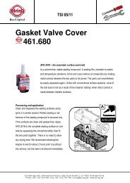
Out-of-Shape Journal<br />
A B C<br />
APPEARANCE<br />
In general, if a bearing has failed because of an out-of-shape journal, an uneven wear pattern is visible on the<br />
bearing surface. Specifically, however, these wear areas can be in any one of three patterns: Photo A above<br />
shows the wear pattern caused by a tapered journal. Photo B shows the wear pattern caused by an hourglass<br />
shaped journal. Photo C shows the pattern of a barrel shaped journal.<br />
DAMAGING ACTION<br />
An out-of-shape journal imposes an uneven distribution of the load on the bearing surface, increasing heat<br />
generated and thus accelerating bearing wear. An out-of-shape journal also affects the bearing’s oil clearance,<br />
making it insufficient in some areas and excessive in others,<br />
thereby upsetting the proper functioning of the lubrication system.<br />
POSSIBLE CAUSES<br />
If the journal is tapered there are two possible causes:<br />
1. Uneven wear of the journal during operation (misaligned rod).<br />
2. Improper machining of the journal at some previous time.<br />
If the journal is hour-glass or barrel shaped, this is usually the<br />
result of improper machining or polishing.<br />
CORRECTIVE ACTION<br />
Regrinding the crankshaft can best remedy out-of-shape journal<br />
problems. Then install new bearings in accordance with proper<br />
installation procedures.<br />
Engine <strong>Bearing</strong> <strong>Failure</strong> & <strong>Analysis</strong> <strong>Guide</strong><br />
14
Oil Starvation<br />
APPEARANCE<br />
When a bearing has failed due to oil starvation, its surface is usually very shiny. In addition, there may be<br />
excessive wear of the bearing surface due to the wiping action of the journal. In the most severe cases the<br />
bearing surface will be smeared or scratched and torn. The bearing will begin to turn dark blue to black in color.<br />
DAMAGING ACTION<br />
The absence of a sufficient oil film between the bearing and the journal permits metal-to-metal contact. The<br />
resulting wiping action causes premature bearing fatigue.<br />
POSSIBLE CAUSES<br />
1. Insufficient oil clearance – usually the result of utilizing a replacement bearing that has too great a wall<br />
thickness. In some cases, the journal may be oversize.<br />
2. Broken or plugged oil passages, prohibiting proper oil flow.<br />
3. A blocked oil suction screen or oil filter.<br />
4. A malfunctioning oil pump or pressure relief valve.<br />
5. Misassembling main bearings metering off an oil hole.<br />
6. Lubrication system not primed before start up.<br />
CORRECTIVE ACTION<br />
1. Double-check all measurements taken during the bearing selection procedure to catch any errors in calculation.<br />
(During assembly check oil clearance with Plastigage ® .)<br />
2. Check to be sure that the replacement bearing you are about to install is the correct one for the application.<br />
3. Check the journals for damage and regrind if necessary.<br />
4. Check engine for possible blockage of oil passages, oil suction screen and oil filter.<br />
5. Check the operation of the oil pump and pressure relief valve.<br />
6. Be sure that the oil holes are properly indexed when installing the replacement bearings.<br />
7. Advise the operator about the results of engine lugging.<br />
8. Always prime the lubrication system before the engine is started the first time.<br />
15<br />
Engine <strong>Bearing</strong> <strong>Failure</strong> & <strong>Analysis</strong> <strong>Guide</strong>
Hot Short<br />
APPEARANCE<br />
<strong>Bearing</strong> surface wiped and torn, blackened from heat, with patches of lining material torn cleanly from steel<br />
backing.<br />
POSSIBLE CAUSES<br />
1. Breakdown of lubrication and resulting high friction elevates operating temperature.<br />
2. Lead in bearing material melts and allows shaft to tear away patches of bearing lining.<br />
3. Lack of lubrication.<br />
4. Wiping.<br />
5. Dirt contamination.<br />
6. Concentrated loading (misalignment, etc.).<br />
CORRECTIVE ACTION<br />
A hot short is a catastrophic failure that results from one of the conditions already covered in detail. To properly<br />
correct this it must first be determined which specific condition lead to the hot short. For further details please<br />
see:<br />
1. Foreign Particles in Lining (Page 3)<br />
2. Foreign Particles on <strong>Bearing</strong> Back (Page 4)<br />
3. Out-of-Round Bore (Page 13)<br />
4. Excessive Crush (Page 7)<br />
5. Bent or Twisted Connecting Rod (Page 9)<br />
6. Shifted <strong>Bearing</strong> Cap (Page 6)<br />
7. Distorted Crankcase (Page 11)<br />
8. Bent Crankshaft (Page 12)<br />
9. Oil Starvation (Page 15)<br />
10. Misassembly (Page 5)<br />
Engine <strong>Bearing</strong> <strong>Failure</strong> & <strong>Analysis</strong> <strong>Guide</strong><br />
16
Surface Fatigue<br />
APPEARANCE<br />
<strong>Bearing</strong> surface cracked, small irregular areas of surface material<br />
missing from the bearing lining.<br />
DAMAGING ACTION<br />
Heavy pulsating loads imposed upon the bearing by reciprocating<br />
motion within the engine cause the bearing surface to crack due to<br />
metal fatigue.<br />
Fatigue cracks widen and deepen perpendicular to the bond line. Close<br />
to the bond line, fatigue cracks turn and run parallel to the bond line,<br />
eventually joining and causing pieces of the surface to flake out.<br />
POSSIBLE CAUSES<br />
1. Overloading (lugging, detonation, or overfueling).<br />
2. Uneven loading (see sections on misalignment).<br />
3. <strong>Bearing</strong> material of inadequate fatigue strength for application.<br />
4. <strong>Bearing</strong> failure due to surface fatigue can be the result of the normal life span of the bearing being exceeded.<br />
CORRECTIVE ACTION<br />
1. If the service life for the old bearing was adequate, replace with the same type of bearing to obtain a similar<br />
service life.<br />
2. If the service life of the old bearing was too short, replace with a heavier duty bearing to obtain a longer life.<br />
3. Replace all other bearings (main connecting rod and camshaft) as their remaining service life may be short.<br />
4. Recommend that the operator avoid “hot rodding” and “lugging” as these tend to shorten bearing life.<br />
5. Check for misassembly. Use proper installation techniques.<br />
17<br />
Engine <strong>Bearing</strong> <strong>Failure</strong> & <strong>Analysis</strong> <strong>Guide</strong>
Corrosion<br />
APPEARANCE<br />
<strong>Bearing</strong> surface darkened, spongy, etched by chemical attack.<br />
DAMAGING ACTION<br />
This is usually the result of contamination of the oil from either the fuel system or internal engine leaks. This<br />
condition is further pronounced when there is poor routine maintenance.<br />
POSSIBLE CAUSES<br />
1. Acids in oil.<br />
2. Excessive operating temperature.<br />
3. Excessive blow-by.<br />
4. Coolant contamination of oil.<br />
5. Use of high sulfur fuel.<br />
6. Excessive oil change interval.<br />
CORRECTIVE ACTION<br />
1. Identify and correct source of contamination.<br />
2. Install new bearings using correct installation procedures.<br />
3. Use a better quality fuel, if possible.<br />
4. Oil should be changed at recommended intervals using the proper grade and rating. In some applications oil<br />
analysis may be needed to determine the optimum oil change intervals.<br />
Engine <strong>Bearing</strong> <strong>Failure</strong> & <strong>Analysis</strong> <strong>Guide</strong><br />
18
Accelerated Wear<br />
APPEARANCE<br />
Wall thickness reduced from original dimension. <strong>Bearing</strong> surface worn and polished but not smeared, torn or<br />
scored. No evidence of heat, no embedded foreign particles.<br />
DAMAGING ACTION<br />
Grinding and polishing the crankshaft journals produce burrs that are so small that we can’t see or feel them.<br />
Not only is it important that the surface finish meet recommended average Ra or better, but it is also important<br />
to always grind opposite to rotation and polish in the direction of rotation. Otherwise it is possible for these<br />
microscopic burrs to disrupt the oil film and abrade away the bearing surface.<br />
POSSIBLE CAUSES<br />
1. Poor journal surface finish.<br />
2. Wear in the presence of adequate lubrication to prevent heat build-up and wiping is caused by peaks in the<br />
journal surface finish profile which penetrate the oil film and abrade the bearing.<br />
CORRECTIVE ACTION<br />
1. Check journal surface finish for proper average Ra and regrind as needed.<br />
2. If surface finish is acceptable lightly re-polish in the direction of rotation.<br />
3. Install new bearings.<br />
19<br />
Engine <strong>Bearing</strong> <strong>Failure</strong> & <strong>Analysis</strong> <strong>Guide</strong>
Crankshaft Grinding<br />
And Polishing<br />
Crankshaft journal surfaces should be ground and<br />
polished to a surface finish of 15 micro inches roughness<br />
average Ra or better. Journals on highly loaded<br />
crankshafts such as diesel engines or high performance<br />
racing engines require a finish of 10 micro<br />
inches Ra or better.<br />
The above is a simple straight forward specification<br />
which can be measured with special equipment.<br />
However, there is more to generating a ground and<br />
polished surface than just meeting the roughness<br />
specification. To prevent rapid, premature wear of the<br />
crankshaft bearings and to aid in the formation of an<br />
oil film, journal surfaces must be ground opposite to<br />
engine rotation and polished in the direction of rotation.<br />
This recommendation can cause a great deal of<br />
confusion in actual execution. Understanding the<br />
reasons behind the recommendation and examination<br />
of the following illustrations will help make the recommendation<br />
more clear.<br />
Metal removal tends to raise burrs. This is true of<br />
nearly all metal removal processes. Different processes<br />
create different types of burrs. Grinding and<br />
polishing produces burrs that are so small that we<br />
can’t see or feel them but they are there and can<br />
damage bearings if the shaft surface is not generated<br />
in the proper way. Rather than “burrs,” let’s call what<br />
results from grinding and polishing “microscopic fuzz.”<br />
This better describes what is left by these processes.<br />
This microscopic fuzz has a grain or lay to it like the<br />
hair on a dog’s back. Figure 1 is an illustration depicting<br />
the lay of this fuzz on a journal. (Note: All figures<br />
are viewed from nose end of crankshaft.) The direction<br />
in which a grinding wheel or polishing belt passes<br />
over the journal surface will determine the lay of the<br />
micro fuzz.<br />
In order to remove this fuzz from the surface, each<br />
successive operation should pass over the journal in<br />
the opposite direction so that the fuzz will be bent over<br />
backward and removed. Polishing in the same direction<br />
as grinding would not effectively remove this fuzz<br />
because it would merely lay down and then spring up<br />
again. Polishing must, therefore, be done opposite to<br />
grinding in order to improve the surface.<br />
In order to arrive at how a shaft should be ground and<br />
polished, we must first determine the desired end<br />
result and then work backwards to establish how to<br />
achieve it. Figure 2 depicts a shaft turning in a bearing<br />
viewed from the front of a normal clockwise rotating<br />
engine. The desired condition is a journal with any<br />
fuzz left by the polishing operation oriented so it will lay<br />
down as the shaft passes over the bearing (Figure 2).<br />
The analogy to the shaft passing over the bearing is<br />
like petting a dog from head to tail. A shaft polished in<br />
the opposite direction produces abrasion to the bearing<br />
which would be like petting a dog from tail to head.<br />
To generate a surface lay like that shown in Figure 2,<br />
the polishing belt must pass over the shaft surface as<br />
shown in Figure 3.<br />
The direction of shaft rotation during polishing is not<br />
critical if a motorized belt type polisher is used be-<br />
Engine <strong>Bearing</strong> <strong>Failure</strong> & <strong>Analysis</strong> <strong>Guide</strong><br />
20
the surface lay is reversed by \ the polishing operation<br />
removing fuzz created by grinding and leaving a<br />
surface lay which will not abrade the bearing surface.<br />
Nodular cast iron shafts are particularly difficult to<br />
grind and polish because of the structure of the iron.<br />
cause the belt runs much faster than the shaft. If a<br />
nutcracker-type polisher is used, then proper shaft<br />
rotation must be observed (Figure 4). Stock removal<br />
during polishing must not exceed .0002” on the diameter.<br />
Nodular iron gets its name from the nodular form of<br />
the graphite in this material. Grinding opens graphite<br />
nodules located at the surface of the journal leaving<br />
ragged edges which will damage a bearing. Polishing<br />
in the proper direction will remove the ragged edges<br />
from these open nodules.<br />
Having determined the desired surface lay from<br />
polishing, we must next establish the proper direction<br />
for grinding to produce a surface lay opposite to that<br />
resulting from polishing. Figure 5 shows the grinding<br />
wheel and shaft directions of rotation and surface lay<br />
for grinding when viewed from the front or nose end of<br />
the crankshaft. This orientation will be achieved by<br />
chucking the flywheel flange at the left side of the<br />
grinder (in the headstock). Achieving the best possible<br />
surface finish during grinding will reduce the stock<br />
removal necessary during polishing.<br />
All of the above is based on normal clockwise engine<br />
rotation when viewed from the front of the engine. For<br />
crankshafts which rotate counterclockwise, such as<br />
some marine engines, the crankshaft should be<br />
chucked at its opposite end during grinding and<br />
polishing. This is the same as viewing the crank from<br />
the flanged end rather than the nose end in the accompanying<br />
figures.<br />
The surface lay generated by grinding would cause<br />
abrasion to the bearing surfaces if left unpolished. By<br />
polishing in the direction shown in either Figure 3 or 4,<br />
21<br />
Engine <strong>Bearing</strong> <strong>Failure</strong> & <strong>Analysis</strong> <strong>Guide</strong>
Premature Thrust<br />
<strong>Bearing</strong> <strong>Failure</strong><br />
BACKGROUND<br />
Although thrust bearings run on a thin film of oil, just like radial journal (connecting rod and main) bearings, they<br />
cannot support nearly as much load. While radial bearings can carry loads measured in thousands of pounds<br />
per square inch of projected bearing area, thrust bearings can only support loads of a few hundred psi. Radial<br />
journal bearings develop their higher load capacity from the way the curved surfaces of the bearing and journal<br />
meet to form a wedge. Shaft rotation pulls oil into this wedge shaped area of the clearance space to create an<br />
oil film, which actually supports the shaft. Thrust bearings typically consist of two flat mating surfaces with no<br />
natural wedge shape in the clearance space to promote the formation of an oil film to support the load.<br />
Conventional thrust bearings are made by incorporating flanges at the ends of a radial journal bearing. This provides<br />
ease in assembly and this design has been used successfully for many years. Either tear-drop or through<br />
grooves on the flange faces and wedge shaped ramps at each parting line allow oil to enter between the shaft and<br />
bearing surfaces. However, the vast majority of the bearing surfaces and the entire shaft surface are flat making it<br />
much harder to create and maintain an oil film. If you have ever taken two gauge blocks and wiped them perfectly<br />
clean and pressed them together with a twisting action you know that they will stick together. This is very much like<br />
what happens as a thrust load applied to the end of a crankshaft squeezes the oil out from between the shaft and<br />
bearing surfaces. If the load is too great, the oil film collapses and the surfaces want to stick together, resulting in<br />
a wiping failure.<br />
For many years some heavy-duty diesel engines have used separate thrust washers with a profiled face to enable<br />
them to support higher thrust loads. These thrust washers either have multiple tapered ramps and relatively small<br />
flat pads or have curved surfaces that follow a sine wave contour around their circumference.<br />
CAUSES OF FAILURE<br />
Aside from the obvious causes, such as dirt contamination and misassembly, there are only three common<br />
factors that generally cause thrust bearing failures. These are:<br />
• Poor crankshaft surface finish<br />
• Misalignment<br />
• External overloading<br />
SURFACE FINISH<br />
Crankshaft thrust faces are difficult to grind because they are done using the side of the grinding wheel. Grinding<br />
marks left on the crankshaft face produce a visual swirl or sunburst pattern with scratches sometimes crisscrossing<br />
one another in a crosshatch pattern similar to hone marks on a cylinder wall. If these grinding marks are<br />
not completely removed by polishing, they will remove the oil film from the surface of the thrust bearing much like<br />
multiple windshield wiper blades.<br />
A properly finished crankshaft thrust face should only have very fine polishing marks that go around the thrust<br />
surface in a circumferential pattern. A surface finish of 15 Ra or less is recommended (10 Ra or less for heavy<br />
duty or highly loaded engines).<br />
ALIGNMENT<br />
The grinding wheel side face must be dressed periodically to provide a clean, sharp cutting surface. A grinding<br />
wheel that does not cut cleanly may create hot spots on the work piece leading to a wavy, out-of-flat surface. The<br />
side of the wheel must also be dressed at exactly 90° to its OD to produce a thrust face that is square to the axis<br />
of the main bearing journal.<br />
Engine <strong>Bearing</strong> <strong>Failure</strong> & <strong>Analysis</strong> <strong>Guide</strong><br />
22
When assembling thrust bearings:<br />
1. Tighten main cap bolts to approximately 10 to 15 ft. lbs. to seat bearings then loosen.<br />
2. Tap main cap toward rear of engine with a soft-faced hammer.<br />
3. Tighten main cap bolts, finger tight.<br />
4. Using a bar, force the crankshaft as far forward in the block as possible to align bearing rear thrust faces.<br />
5. While holding shaft in forward position, tighten main cap bolts to 10 to 15 ft lbs.<br />
6. Complete tightening main cap bolts to specifications in 2 or 3 equal steps.<br />
The above procedure should align the bearing thrust faces with the crankshaft to maximize the amount of bearing<br />
area in contact for load carrying.<br />
LOADING<br />
A number of factors may contribute to wear and overloading of a thrust bearing, such as (in no specific order):<br />
• Excessive pump pressure<br />
• Torque converter expansion<br />
• Torque converter internal wear<br />
• Pump drive gear installed backwards<br />
• Wrong torque converter<br />
• Wrong flex plate<br />
• Wrong flywheel bolts<br />
• Misalignment of the engine and the major transmission components<br />
• Improper throw out bearing adjustment<br />
• Riding the clutch pedal<br />
DIAGNOSING PROBLEMS<br />
By the time a thrust bearing failure becomes evident, the parts have usually been so severely damaged that there<br />
is little if any evidence of the cause. The bearing is generally worn into the steel backing which has severely worn<br />
the crankshaft thrust face as well. So how do you tell what happened?<br />
Start by looking for the most obvious internal sources:<br />
• Is there evidence of distress anywhere else in the engine that would indicate a lubrication problem or<br />
foreign particle contamination?<br />
• Were the proper bearing shells installed correctly?<br />
• If the thrust bearing is in an end position, was the adjacent oil seal correctly installed? An incorrectly<br />
installed rope seal can cause sufficient heat to disrupt bearing lubrication.<br />
• Examine the un-failed thrust face on the crankshaft for surface finish and geometry. This may give an<br />
indication of the original quality of the failed face.<br />
• Once you are satisfied that all potential internal sources have been eliminated; ask about potential external<br />
sources of either overloading or misalignment.<br />
• Did the vehicle have a prior thrust bearing failure?<br />
• What external parts were replaced?<br />
• Was the correct transmission installed?<br />
• Was the correct torque converter installed?<br />
23<br />
Engine <strong>Bearing</strong> <strong>Failure</strong> & <strong>Analysis</strong> <strong>Guide</strong>
• Was the correct flex plate used? At installation there should be a minimum of 1/16” (1/8” preferred) clearance<br />
between the flex plate and converter to allow for converter expansion.<br />
• Were the correct flex plate mounting bolts used?<br />
• Is there evidence of the converter hitting the flex plate mounting bolts?<br />
• Was the transmission properly aligned to the engine?<br />
• Were all dowel pins in place?<br />
• Check condition of pilot bearing.<br />
• If a used torque converter was re-used, is it worn internally?<br />
• If a rebuilt transmission was installed, did the torque converter engage the pump drive spline properly? An<br />
improperly installed pump drive gear may prevent full engagement of the converter.<br />
• Was the transmission pump pressure checked and found to be within specification?<br />
• Check external transmission cooling lines and heat exchanger for restrictions that will increase pump<br />
pressure.<br />
• If a manual transmission was installed, was the throw out bearing properly adjusted?<br />
• What condition was the throw out bearing found to be in? A properly adjusted throw out bearing that is worn<br />
or overheated may indicate the operator was “Riding the Clutch”.<br />
HELP FOR THE THRUST BEARING<br />
When a problem application is encountered, every effort should be made to find the cause of distress and correct<br />
it before completing repairs or you risk a repeat failure.<br />
A simple modification to the upper thrust bearing may help in problem applications. Install the upper thrust bearing<br />
in the block to determine which thrust face is toward the rear of the engine.<br />
Using a small, fine tooth, flat file, increase the chamfer on the ID edge of the bearing parting line from the oil groove<br />
to the rear thrust face only. (See diagram.) This enlarged ID chamfer will allow pressurized oil from the bearing oil<br />
groove to reach the loaded thrust face without passing through the bearings clearance space first. Since there is<br />
a load against the rear thrust face, the load should restrict oil flow and there should not be a noticeable loss in oil<br />
pressure. Although this modification is not a guaranteed cure-all it should help if all other conditions, such as<br />
surface finish, alignment, cleanliness and loading are within reasonable<br />
limits.<br />
RECENT DEVELOPMENTS<br />
In the past few years some new automotive engine designs have<br />
begun using various methods to enable them to carry higher thrust<br />
loads imposed by some of the newer automatic transmissions. The<br />
use of thrust washers exclusively, a combination of thrust washers<br />
and flange bearings, radial grooving (a series of 3 - 5 straight grooves<br />
on the flange face), flange bearings with profiled (ramp and pad design) flange faces, or assembled flanges<br />
(separate thrust washers which are mechanically attached to the bearing). It is important to keep in mind that<br />
most of these developments are application specific and may not be available or even feasible for older applications.<br />
Engine <strong>Bearing</strong> <strong>Failure</strong> & <strong>Analysis</strong> <strong>Guide</strong><br />
24
Crankshaft Thrust Faces<br />
SEVERE USE RECOMMENDATIONS<br />
Crankshaft surface finish and shape are key factors affecting the performance of all bearings. These factors<br />
become even more critical for thrust surfaces. As in any bearing, increased loading reduces oil film thickness<br />
between shaft and bearing surfaces. This is a much more critical situation in thrust bearings due to their flat<br />
faces which make formation of an oil film extremely difficult. Radial bearings (those which carry loads in a radial<br />
direction like rod and main bearings) form a natural wedge where shaft and bearing surfaces come together in<br />
the clearance space. Shaft rotation pulls a wedge of oil into the loaded area of the bearing and forms an oil film<br />
that supports the load.<br />
Thrust faces, on the other hand, are made up of two flat surfaces that do not form a natural wedge where they<br />
meet. In order to help form an oil film, artificial wedge shaped areas are machined into the bearing surfaces at<br />
the ends and sometimes adjacent to the grooves. In spite of all the common design efforts, thrust bearings still<br />
run on a much thinner film of oil that makes crankshaft surface finish critical in the successful performance of<br />
these bearings.<br />
Recent samples of thrust face surface finish on crankshafts from blown fuel “Hemi” engines have confirmed<br />
that better finishes resulted in a reduced rate of bearing distress. The study also showed that when no damage<br />
occurred, the crankshaft surface finish was improved after running. The surface finishes of 12 crankshafts<br />
were measured (7 new and 5 used). The new shafts ranged from a high of 30 Ra to a low of 5 Ra. The used<br />
shafts had a very similar range from 31Ra to 4 Ra. Although this represents only a small sampling, it does<br />
demonstrate a correlation between surface finish and performance when the condition of mating bearing<br />
surfaces was evaluated. Prior to these measurements, race experience had shown no problems on a crankshaft<br />
with a thrust-face Ra of 6 and DID show problems on crankshafts when the Ra was over 20!<br />
Obtaining a good finish on the thrust face of a crankshaft is difficult to do because it uses side-wheel grinding.<br />
Side grinding causes marks that spiral outward toward the OD of the thrust face and may also cause crosshatch<br />
marks resembling honing patterns. Both patterns are detrimental to the formation of an oil film because<br />
they work like wipers as the shaft rotates. Grinding marks must be removed by polishing. Only a circular<br />
pattern should remain. Surface finish should be checked in a tangential direction and must be held to<br />
10 Ra max. The thrust surface should be flat within .0002” max.<br />
AVOID - SWIRL PATTERN<br />
AVOID - CROSSHATCH PATTERN<br />
25<br />
Engine <strong>Bearing</strong> <strong>Failure</strong> & <strong>Analysis</strong> <strong>Guide</strong>
Preventing Premature<br />
Cam <strong>Bearing</strong> <strong>Failure</strong><br />
For many years, nearly all camshaft bearings were manufactured with a lining of babbitt. Babbitt is a soft<br />
slippery material made up primarily of lead and tin and is quite similar to solder. As a bearing surface layer,<br />
babbitt possesses the desirable properties necessary to survive under adverse conditions such as foreign<br />
particle contamination, misalignment and marginal lubrication on start up.<br />
The trend in modern engines has been toward higher operating temperatures and higher valvetrain loads. Babbitt<br />
is limited in its ability to survive under these conditions due to its relatively low strength. When babbitt cam bearings<br />
are installed under these demanding conditions, the lining may extrude or fatigue. Fatigue can be identified by<br />
craters in the bearing surface where sections of lining material have flaked out.<br />
To meet the demands of higher loads and operating temperatures in modern engines as well as the requirements<br />
imposed by high performance, babbitt has been replaced by an alloy of aluminum. This aluminum alloy is much<br />
stronger than babbitt and will withstand several times the load. However, this added strength is obtained at the<br />
expense of some of the more f<strong>org</strong>iving properties of babbitt. The aluminum alloy is harder, making it somewhat<br />
less compatible with dirt, misalignment and marginal lubrication. This is typical of the compromises or trade offs<br />
that are frequently necessary when selecting a bearing material to suit the requirements of a specific application<br />
and in this case, higher loading.<br />
Typically, whenever a higher level of loading is encountered, greater precision is required to maintain reliability.<br />
Conditions such as cleanliness, alignment, clearances, journal surface finishes and lubrication must all be controlled<br />
more closely. Following are some recommendations to help optimize performance when using aluminum<br />
alloy camshaft bearings.<br />
Sufficient clearance is necessary in the initial installation. These stronger bearings will not wear in rapidly to make<br />
their own clearance like softer babbitt materials. Minimum clearance should be .002” for stock engines and .003”<br />
for high performance. Optimum clearance range for high performance applications is .003” to .004”. Because of<br />
the stack up of tolerances on the block, shaft and bearing it is impossible to control clearance to this range in the<br />
manufacture of the bearing alone. Clearances must be measured at installation.<br />
Honing the ID’s of cam bearings to increase clearance is not recommended because hone grit may become<br />
embedded in bearing surfaces that will cause shaft wear. <strong>Bearing</strong> ID’s may be reamed, but the most practical<br />
means is to adjust camshaft journal diameters by grinding the journal. Even if not ground to provide additional<br />
clearance, camshaft bearing journals should be polished to the proper surface finish with the camshaft rotating in<br />
the same direction it will rotate in the engine.<br />
Like clearance, alignment is also extremely important especially for high performance applications. Any block that<br />
has needed to have its main bearing bore alignment corrected due to distortion is likely to have experienced cam<br />
bearing bore distortion as well. Adequate clearance can help compensate for minor misalignment of less than<br />
.001”.<br />
Installation of bearings into the block must be done with care to avoid shaving metal off the backs of the bearings.<br />
This galling action may cause a build-up of metal between the bearing OD and the housing bore which will result<br />
in a reduction in clearance. To prevent galling, check housing bores for a proper 25 to 30 degree lead-in chamfer<br />
before installing cam bearings. On blocks without grooves behind the cam bearings, care must be taken to insure<br />
that oil holes line up between the bearings and block. Where the block has a groove behind the bearing, the<br />
bearing should be installed with the oil hole at the 2 o’clock position when viewed from the front for normal clockwise<br />
camshaft rotation. This will introduce oil into the clearance space outside of the loaded area and allow shaft<br />
rotation to build an oil film ahead of the load.<br />
Engine <strong>Bearing</strong> <strong>Failure</strong> & <strong>Analysis</strong> <strong>Guide</strong><br />
26
Ask your Clevite Sales Representative about our many other quality Clevite engine parts.<br />
1350 Eisenhower Place<br />
Ann Arbor, MI • 48108 • U.S.A.<br />
www.engineparts.com<br />
©2002 Dana Corporation Printed in U.S.A.<br />
Engine <strong>Bearing</strong> <strong>Failure</strong> & <strong>Analysis</strong> <strong>Guide</strong>