USER MANUAL
USER MANUAL
USER MANUAL

You also want an ePaper? Increase the reach of your titles
YUMPU automatically turns print PDFs into web optimized ePapers that Google loves.
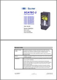
<strong>USER</strong> <strong>MANUAL</strong><br />
FOR DENEX VERSIONS: 2010<br />
DENEX ® MICRO<br />
FLDM 180C1102/S42
READ THIS FIRST<br />
Before installing, operating, opening, or applying the DENEX MICRO sensor, read and<br />
understand the contents of this manual.<br />
Always observe the following warnings and cautions when operating or working on the<br />
equipment.<br />
CAUTION<br />
Use of controls or adjustments or performance procedures other<br />
than those specified herein may result in hazardous radiation exposure.<br />
Do not stare into laser beam.<br />
The DENEX MICRO must be applied, installed, adjusted, and maintained only by qualified<br />
personnel who are familiar with the operation of the unit and its associated components.<br />
User Manual DENEX MICRO 2/24 Baumer Electric AG<br />
Version 2013-02, V1.6 www.baumer.com Frauenfeld, Switzerland
CONTENTS<br />
1 INTRODUCTION _____________________________________________________ 4<br />
2 RECEIVING AND HANDLING _________________________________________ 4<br />
3 BASIC FUNCTION ___________________________________________________ 5<br />
4 INSTALLATION ______________________________________________________ 6<br />
4.1 General Precautions ____________________________________________________ 6<br />
4.2 Mechanical Installation _________________________________________________ 6<br />
4.3 Standard Mounting with Beam Stopper ___________________________________ 7<br />
4.4 Mounting with a hole for the laser ________________________________________ 8<br />
4.5 Mounting With Reference Surface _______________________________________ 9<br />
5 Electrical installation _______________________________________________ 10<br />
5.1 Power Connection ____________________________________________________ 10<br />
5.2 Output Signal _________________________________________________________ 10<br />
5.2.1 Output Signal - Connections _____________________________________ 10<br />
5.2.2 Speed Sensor Input _____________________________________________ 11<br />
6 SOFTWARE FUNCTIONS ____________________________________________ 12<br />
6.1 Application Setting ____________________________________________________ 12<br />
6.2 Blocking Function _____________________________________________________ 12<br />
6.3 Back-Edge Check (In counting mode) ___________________________________ 12<br />
6.4 DIP-Switch Settings ___________________________________________________ 13<br />
7 LED INDICATORS __________________________________________________ 14<br />
7.1 The POWER-LED ______________________________________________________ 14<br />
7.2 The LASER OFF-LED __________________________________________________ 14<br />
8 TECHNICAL SPECIFICATIONS ______________________________________ 15<br />
9 LASER SAFETY ____________________________________________________ 16<br />
10 SAFETY __________________________________________________________ 17<br />
10.1 Safety Features _____________________________________________________ 17<br />
10.1.1 Power Control ________________________________________________ 17<br />
10.1.2 Visible Warning-LED __________________________________________ 17<br />
11 MAINTENANCE AND REPAIRS _____________________________________ 17<br />
11.1 Maintenance at Regular Intervals _____________________________________ 17<br />
12 RETURNING EQUIPMENT _________________________________________ 18<br />
13 WARRANTY ______________________________________________________ 18<br />
14 TROUBLESHOOTING _____________________________________________ 19<br />
15 APPENDIX _______________________________________________________ 22<br />
16 Supplements _____________________________________________________ 23<br />
User Manual DENEX MICRO 3/24 Baumer Electric AG<br />
Version 2013-02, V1.6 www.baumer.com Frauenfeld, Switzerland
1 INTRODUCTION<br />
We strongly recommend you to read section regarding laser safety before switching on the<br />
equipment.<br />
WARNING<br />
When the DENEX MICRO is combined with user<br />
selected components to form a system, the user is responsible for proper selection of parts<br />
and subsequent operation. This unit shall be installed, adjusted and serviced only by<br />
qualified personnel who are familiar with the operation of the DENEX MICRO and other<br />
system components. Serious personal injury and equipment damage may result if this<br />
procedure is not followed.<br />
2 RECEIVING AND HANDLING<br />
Upon delivery of the equipment, thoroughly inspect the shipping containers and contents<br />
for indications of damage incurred in transit. If any concealed loss or damage is<br />
discovered later, notify the freight or express agent.<br />
User Manual DENEX MICRO 4/24 Baumer Electric AG<br />
Version 2013-02, V1.6 www.baumer.com Frauenfeld, Switzerland
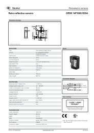
3 BASIC FUNCTION<br />
The DENEX MICRO is a non-contact sensor which counts all kinds of printed products on<br />
an overlapped stream. It senses the leading edge and generates one output pulse for<br />
every product. Product thickness from a single folded sheet up to a maximum stream<br />
thickness of 70 mm can be sensed without adjustments.<br />
The laser diode that is used produces a visible and very intensive and focused light beam<br />
which is projected onto the stream. The reflected light from the spot is collected by two<br />
light sensitive detectors P and R and is analyzed by a microprocessor. The difference in<br />
reflected light that occurs when the light spot is temporarily hidden behind the passing<br />
product edge provides the basic data for the sensor to determine a count output pulse.<br />
Figure 3.1 The principle of operation<br />
The patented principle in utilizing two detectors - one for detecting the obstructed light and<br />
the other for reference, enables the following unique benefits:<br />
Wide operating range<br />
High precision<br />
Insensitive to color of paper or print<br />
Insensitive to product thickness<br />
Insensitive to variations in distance to copy stream<br />
The use of a microprocessor further enhances the flexibility and reliability of the unit.<br />
Through the use of the microprocessor, the DENEX MICRO can be adapted to different<br />
operating modes by changing DIP-switch settings which can be reached from outside, via<br />
the glass window.<br />
User Manual DENEX MICRO 5/24 Baumer Electric AG<br />
Version 2013-02, V1.6 www.baumer.com Frauenfeld, Switzerland
4 INSTALLATION<br />
In order to assure the best possible operating conditions as well as personal safety, it is<br />
essential that the following instructions are followed exactly.<br />
4.1 General Precautions<br />
The DENEX MICRO should be installed in an environment where:<br />
1. The equipment ambient temperature does not exceed 40º C.<br />
2. The equipment atmosphere is free from highly flammable or combustible vapors,<br />
corrosive chemical flumes, oil vapor, steam, excessive moisture and particles.<br />
Avoid mounting the unit in places with strong vibrations since they can produce miscounts,<br />
especially when thin products are counted. Make sure that the mounting bracket and<br />
means used are rigid to withstand vibrations.<br />
The sensor should normally be mounted on a flat conveyor. It is possible to mount the<br />
sensor on a bent part of the conveyor according to figures below. Do not mount according<br />
to Figure 4.1.1 (right) since it will deteriorate the function of the unit.<br />
YES<br />
NO<br />
Figure 4.1.1 Mounting on a non-flat conveyor.<br />
4.2 Mechanical Installation<br />
The sensor should be mounted parallel to, and at a distance of 100 mm from the conveyor.<br />
The sensor will then count folded sheets up to a maximum stream thickness of 70 mm. If<br />
the sensor is to used as a gripper sensor, refer to Appendix 1 ”Mounting and using the<br />
sensor on a gripper conveyor”. Contact Baumer if other mountings are considered. It is<br />
most important that the sensor is mounted the right way. It can only count in one direction.<br />
The connector side of the sensor should be the first to meet the copies.<br />
The laser beam must not hit any moving part of the conveyor. The path of the laser must<br />
end with a beam stopper. See chapters 4.3 and 4.4 for more information about the type of<br />
beam stopper used. The laser beam must never be accessible to the user!<br />
Make sure that the mounting bracket used is rigid and that the alignment of the unit cannot<br />
be accidentally changed. There are brackets available from Baumer.<br />
User Manual DENEX MICRO 6/24 Baumer Electric AG<br />
Version 2013-02, V1.6 www.baumer.com Frauenfeld, Switzerland
4.3 Standard Mounting with Beam Stopper<br />
The laser does not hit anything except the beam stopper when no copies are present.<br />
Normal back-edges will not be counted with this mounting. The beam stopper is a black<br />
plate or dark surface no closer than 300 mm to the bottom of the sensor. See figure 4.3.1.<br />
100<br />
Figure 4.3.1 Standard mounting with beam stopper.<br />
User Manual DENEX MICRO 7/24 Baumer Electric AG<br />
Version 2013-02, V1.6 www.baumer.com Frauenfeld, Switzerland
4.4 Mounting with a hole for the laser<br />
If there are mechanical parts 200-300 mm under the sensor that can cause reflections to<br />
the detectors, the following mounting is recommended. It requires a small hole on the<br />
conveyor, or a plate with a hole to screen off the reflection from the parts. The beam must<br />
still be stopped with a dark plate or other material if there is any risk for a person to look<br />
into the laser. Make sure that the laser goes through the hole properly. Normal back-edges<br />
are not counted with this mounting.<br />
100<br />
Figure 4.4.1 Mounting with a hole to let the laser through.<br />
User Manual DENEX MICRO 8/24 Baumer Electric AG<br />
Version 2013-02, V1.6 www.baumer.com Frauenfeld, Switzerland
4.5 Mounting With Reference Surface<br />
In some cases, the reflections from parts under the conveyor cannot be screened off. In<br />
this case, the following is recommended. Let the laser hit a light, matte surface, reference<br />
surface, like a white piece of paper or a light painted plate, at 100 mm below the sensor.<br />
The reference surface must be smooth. If the surface is wrinkled or coarse, vibrations can<br />
cause error pulses. Also, make sure that dust and paper pieces do not stay on the surface,<br />
since they might create extra pulses. No extra beam stopper is needed.<br />
The accuracy can be equally good if: no up-bent back edges are present, stream is regular<br />
with few gaps.<br />
Up-bended back edges can produce output pulses. This mounting is only recommended in<br />
applications with few gaps in the stream.<br />
100<br />
Figure 4.5.1 Mounting with reference surface<br />
.<br />
User Manual DENEX MICRO 9/24 Baumer Electric AG<br />
Version 2013-02, V1.6 www.baumer.com Frauenfeld, Switzerland
5 Electrical installation<br />
The interface to the copy sensor is a 7-pin connector with the following pin-out:<br />
Matching connector: Amphenol Tuchel T3476 001, delivered with the sensor.<br />
Pin 1 :<br />
Pin 2 :<br />
Pin 3 :<br />
Pin 4 :<br />
Pin 5 :<br />
Pin 6 :<br />
Pin 7 :<br />
+24VDC power<br />
+ Output (collector)<br />
+ Speed Sensor Input<br />
- Speed Sensor Input<br />
- Output (emitter)<br />
0V<br />
No function (connected to pin 6 internally)<br />
5.1 Power Connection<br />
Proper wiring techniques are essential for successful system installation. To reduce the<br />
effects of electrical noise interference and static discharge, the procedures outlined in this<br />
section must be strictly followed.<br />
The sensor shall be connected to 19 - 30V DC regulated power.<br />
It must be free from transients!<br />
Never connect or disconnect any cables when the power is on!<br />
The normal current consumption is around 200mA<br />
5.2 Output Signal<br />
The output is a normally open, opto-isolated transistor. Every output pulse is signaled as a<br />
closing of the output for a certain time; see also “DIP-Switch Settings” in chapter 5.<br />
The spec for the output opto coupler is as follows:<br />
Max load current: 150mA, Max voltage: 35V DC<br />
5.2.1 Output Signal - Connections<br />
The output can be used for both "current source" and "current sink" depending on what is<br />
required for the following equipment. In current source mode, the sensor output will give a<br />
positive pulse to the stacker/totalizer when active. In current sink mode, the sensor output<br />
will give a negative pulse. Figures 5.2.1.1 and 5.2.1.2 shows a common 24V as power<br />
supply and as the supply for the pulse. It is of course possible to have different power<br />
supplies. In that case, the 24V-power is connected to pins 1 and 6, and the totalizer is<br />
connected to pins 2 and 5.<br />
Figure 5.2.1.1 Electrical connection, common 24V-supply. Current source (PNP).<br />
User Manual DENEX MICRO 10/24 Baumer Electric AG<br />
Version 2013-02, V1.6 www.baumer.com Frauenfeld, Switzerland
Figure 5.2.1.2 Electrical connection, common 24V-supply. Current sink (NPN).<br />
Copy Sensor<br />
Figure 5.2.1.3 Electrical connection, separate supply for power and pulse.<br />
5.2.2 Speed Sensor Input<br />
There is a possibility to connect an input signal from a speed sensor, such as an encoder,<br />
in order to give information of conveyor speed. The input can be used to obtain a fixed<br />
blocking distance. In Mode 7 (see chapter 6, “SOFTWARE FUNCTIONS”) the input signal<br />
is used as a control signal, if high, the blocking time is long, if low, the blocking time is<br />
short. Normally, the dynamic blocking is used with equally good results. There are three<br />
different modes of blocking, see chapter 6, ”SOFTWARE FUNCTIONS”.<br />
The input is opto-isolated so that there is a separation between the sensor’s and the pulse<br />
generator’s grounds.<br />
The input should be min. 4.5V and max. 28V.<br />
The maximum allowed frequency is 2.5 kHz.<br />
Figure 5.2.2.1 Input stage for speed sensor input.<br />
User Manual DENEX MICRO 11/24 Baumer Electric AG<br />
Version 2013-02, V1.6 www.baumer.com Frauenfeld, Switzerland
6 SOFTWARE FUNCTIONS<br />
The real power with a microprocessor-based sensor is that the sensor learns what the<br />
products and the stream look like and make decisions according to this. Before actual<br />
settings are discussed, first a short description of the major functions and terms.<br />
6.1 Application Setting<br />
The sensor can be optimized around certain applications. Things like output pulse width,<br />
Blocking Function and Back Edge Check parameters are set a little different for each<br />
application in order to reach the highest possible accuracy.<br />
There are four DIP-switches that tell the sensor which application it should be set for.<br />
It is very important to set the right application!<br />
6.2 Blocking Function<br />
This function will eliminate false counts due to double edges or a cut-edge-first delivery.<br />
The sensor will count edges coming within the blocking zone as one product. In<br />
productions using stitches, extra pulses due to the stitch are blocked out by this function.<br />
The blocking zone is a dynamic value that constantly adapts to the average distance<br />
between copies. It will be either 15% or 30 % of the mean lap, depending on application.<br />
The average distance between copies is 100%, see figure 6.2.1.<br />
Figure 6.2.1 The principle of the blocking function.<br />
The blocking zone is marked with gray. 15% is the first half, and 30% is whole area.<br />
6.3 Back-Edge Check (In counting mode)<br />
Normal flat back-edges are never counted. However, if the back-edge is bent, this part of<br />
the paper can result in a miscount. The sensor can be configured to wait a certain time to<br />
decide whether the edge that was found was really a copy or if it was an up bent backedge<br />
of the product, or a pin hole on the back of the paper. DIP-switches must be set to<br />
choose Newspaper-application in order to activate this function.<br />
The Back-Edge Check will affect the timing of the output pulse also on normal edges, but<br />
will give a higher counting accuracy. Therefore, in timing applications like edge detecting,<br />
the Back-Edge Check is disabled.<br />
User Manual DENEX MICRO 12/24 Baumer Electric AG<br />
Version 2013-02, V1.6 www.baumer.com Frauenfeld, Switzerland
6.4 DIP-Switch Settings<br />
An 8-pole DIP-switch can be reached via the lid on top of the sensor. Unscrewing the<br />
screw opens the lid.<br />
The software functions can be controlled via the DIP switches.<br />
DIP-Switch positions<br />
= OFF<br />
= ON<br />
DIP-switches 1-4 are reserved for factory<br />
DIP-switches 5-8 are for selecting operation mode<br />
All in OFF-position is the default setting.<br />
DIP-Switches<br />
5 6 7 8<br />
Mode 0 =<br />
Default<br />
Mode 1<br />
Mode 2<br />
Mode 3<br />
Mode 4<br />
Mode 5<br />
Mode 6<br />
Mode 7<br />
Mode 8<br />
Mode 9<br />
Mode 10<br />
Mode 11<br />
Counting mode: 15% Blocking, short Back-Edge Check, Output 5ms<br />
Thick newspapers: 30% Blocking time, long Back-Edge Check. Output 5 ms<br />
Counting mode: speed pulses, Blocking pulses 5, Back-edge 16, Output: 5ms<br />
Counting mode: speed pulses, Blocking pulses 5, Back-edge 5,Output: 20ms<br />
Thick newspapers, Blocking pulses 20. Back-edge 16, Output: 5ms<br />
Edge detecting: fixed trig, Blocking 15%,No back-edge check, Output: 5ms<br />
Gripper Pulse mode: For gripper conveyors, Blocking 15%, Output 20 ms<br />
Cut edge first mode: Blocking 30 %, Back-edge 15%, Output 5 ms<br />
Counting mode: Speed pulses, Blocking 10, Back-edge 16, Output 5ms<br />
Commercial: Fixed trig, No Blocking, No Back-edge, Output 20 ms<br />
Counting mode: 15% Blocking, short Back-Edge Check, Output 20ms<br />
Counting mode: speed pulses, Blocking pulses 5, Back-edge 16, Output: 5ms<br />
Laser power save mode is activated in all Counting/newspaper modes.<br />
This means the laser power will be reduced after a 60 seconds gap.<br />
User Manual DENEX MICRO 13/24 Baumer Electric AG<br />
Version 2013-02, V1.6 www.baumer.com Frauenfeld, Switzerland
7 LED INDICATORS<br />
As a help for checking the operation of the sensor, there are four LED’s that are placed<br />
close to the connector.<br />
Figure 7.1 Position of LED:s.<br />
7.1 The POWER-LED<br />
The green POWER-LED indicates that the sensor has power and should be operating.<br />
Never mount or adjust the sensor when this LED is on!<br />
7.2 The LASER OFF-LED<br />
The LASER OFF-LED is an indication that the laser is off. The laser will be shut off for the<br />
following reasons:<br />
The laser power has exceeded the allowed limits (electronic problem inside sensor)<br />
The laser power has reached lower than acceptable level (laser is worn out, or<br />
electronic problem)<br />
If the laser levels are outside of the allowed limits, the sensor must be sent for repair.<br />
The OUTPUT-LED is active when the output stage is active (set). The LED will flash for<br />
every output pulse that is sent. The output pulse width can be set with the DIP-switches,<br />
see chapter 5.4, ”DIP-Switch Settings”. By watching this LED, it is fairly easy to see that<br />
the sensor is giving the correct amount of pulses.<br />
User Manual DENEX MICRO 14/24 Baumer Electric AG<br />
Version 2013-02, V1.6 www.baumer.com Frauenfeld, Switzerland
8 TECHNICAL SPECIFICATIONS<br />
Maximum Count Rate<br />
< 600.000 copies/hour<br />
Maximum Product Speed<br />
1 m/s (200 ft/min) for thinnest product, up to 2 m/s otherwise<br />
Maximum Stream Thickness<br />
70 mm (2.76”) standard range<br />
Minimum Product Thickness<br />
0,25 mm (0.01”) standard range,<br />
Distance From Conveyor<br />
100 mm (3.94”) standard range,<br />
Minimum Spacing Between Copies<br />
1-5 mm (0.039-0.20”) dep. on thickness, speed and pulse width<br />
Stream Conditions<br />
All conditions<br />
Operating System<br />
RISC microprocessor<br />
Pulse Width<br />
5 ms (preset) or 20 ms<br />
Output Signal<br />
Opto-isolated 5 to 30 V max. 150 mA<br />
Speed Sensor Input<br />
4.5 - 28 VDC, 3 mA, max. 2.5 kHz<br />
Matching Connector<br />
Amphenol-Tuchel C91A T 3476 001<br />
Laser System<br />
Visible, switched laser diode, 650 nm, with laser safety monitor<br />
Laser Safety Class<br />
Class II<br />
Estimated Lifetime of Laser<br />
> 30,000 h @ 20ºC<br />
Weight<br />
800 g, 1.75 lbs.<br />
Size<br />
175 x 96 x 31mm, 6.89 x 3.78 x 1.22”<br />
Power<br />
24 V DC. 150 mA typical<br />
Temp. Range<br />
+10 to 40ºC, 50 to 104ºF<br />
DENEX MICRO is a Class II Laser Product.<br />
User Manual DENEX MICRO 15/24 Baumer Electric AG<br />
Version 2013-02, V1.6 www.baumer.com Frauenfeld, Switzerland
9 LASER SAFETY<br />
The concentrated beam of optical radiation from the laser diode is potentially dangerous.<br />
In considering the safety aspects of the use of such devices, it is the thermal effects of<br />
absorption of this energy, which are important. However, in comparison with higher power<br />
laser using different generating media, laser diodes are relatively safe.<br />
A Class II-laser product as the DENEX MICRO is said to be safe if a person does not stare<br />
into the beam. If a person accidentally would look into the laser, the strong light would<br />
cause the eyes to shut automatically before any damage to the eyes could occur. If the<br />
following precautions are followed, nothing can happen.<br />
CAUTION<br />
• Do not stare into the laser beam or a reflection of the beam from a mirror-like<br />
surface!<br />
• Do not move or adjust the DENEX MICRO, without first turning off the power!<br />
The green LED must be off!<br />
• Service on the sensor should be made by qualified personnel only!<br />
• The sensor must be installed in such way, that the laser does not hit a glossy,<br />
mirror-like surface!<br />
CAUTION<br />
Use of controls or adjustments other than those specified herein may result in hazardous<br />
radiation exposure.<br />
Do not stare into beam!<br />
User Manual DENEX MICRO 16/24 Baumer Electric AG<br />
Version 2013-02, V1.6 www.baumer.com Frauenfeld, Switzerland
10 SAFETY<br />
10.1 Safety Features<br />
The following chapter describes the safety features of the DENEX MICRO. Make regular<br />
checks to verify the function of these features.<br />
10.1.1 Power Control<br />
To power off the sensor, unplug the power connection.<br />
10.1.2 Visible Warning-LED<br />
The green LED is the POWER-LED, which indicates that the laser is on!<br />
Never move or adjust the sensor when the green LED is on!<br />
11 MAINTENANCE AND REPAIRS<br />
Before any adjustments or maintenance is carried out on the DENEX MICRO, make sure<br />
to follow the instructions below:<br />
Switch off the power by removing the power plug.<br />
11.1 Maintenance at Regular Intervals<br />
The only maintenance on the sensor which is allowed by non-DENEX Sensor authorized<br />
personnel is cleaning the glass window, but only after first turning the sensor off.<br />
- Clean the glass aperture with alcohol<br />
- Remove any loose pieces of paper that can produce false counts<br />
- Check that the beam stopper is in place and that it is not covered with dust<br />
CAUTION<br />
Use of controls or adjustments other than those specified<br />
herein may result in hazardous radiation exposure.<br />
Diode laser power up to 1 mW at 670 nm can be accessible in the interior.<br />
Avoid exposure to beam!<br />
User Manual DENEX MICRO 17/24 Baumer Electric AG<br />
Version 2013-02, V1.6 www.baumer.com Frauenfeld, Switzerland
12 RETURNING EQUIPMENT<br />
If it is necessary to return a DENEX MICRO for repair, the following procedure should be<br />
followed.<br />
1. Tag the unit with the following:<br />
• Company and contact person returning the item<br />
• Phone, fax or email to the contact person for additional information<br />
• Helpful information regarding the malfunction. A good description reduces<br />
trouble shooting cost.<br />
If the unit has been disassembled, reassemble it, making certain that all hardware is in<br />
place. Missing parts will be charged at spare part prices.<br />
2. Carefully pack the unit and apply appropriate cautionary stickers.<br />
3. Advice way of returning the unit: Post (DPD), UPS, DHL or other.<br />
4. Return unit to your dealer or directly to Baumer (see address on back page).<br />
13 WARRANTY<br />
Baumer Electric AG gives a warranty to the customer for quality and suitability of its<br />
products within the scope of its technical specifications. A warranty is only given according<br />
to prior agreement for parts which are used as safety parts within the meaning of the EU<br />
Machinery Directive. The guarantee of Baumer Electric AG is limited to replacement or<br />
repair of defective parts and causes which occurred before the passing of risk. Liability for<br />
further direct and indirect losses are excluded to the extent permissible at law, more<br />
particularly, no compensation shall be owed for any incidental loss, loss of production etc.<br />
The guarantee lapses in any event if the customer does not use original Baumer Electric<br />
AG replacement parts. The guarantee is not valid in any instance where the goods have<br />
been tampered with. The customer is under a duty to examine the consignment for<br />
completeness and transport damage immediately on receipt. Any complaints in connection<br />
with the product shall be made in writing without delay, and evidence of such incidence<br />
must be produced. Complaints may be made about product defects during the complete<br />
period of guarantee at any time before and/or after processing and/or re-sale, but they are<br />
to be notified in writing enclosing the defective part without delay after emergence. The<br />
customer may only invoke these guarantee conditions if he proves that the defects<br />
emerged despite proper assembly and use. The guaranty period is 24 months from<br />
dispatch from Baumer Electric AG. The period of guarantee for replacement parts or<br />
repairs delivered under guarantee ends with the period for the products originally supplied.<br />
Baumer Electric AG reserves the right to charge the processing costs for sales returns and<br />
performance tests without claim to guarantee.<br />
User Manual DENEX MICRO 18/24 Baumer Electric AG<br />
Version 2013-02, V1.6 www.baumer.com Frauenfeld, Switzerland
14 TROUBLESHOOTING<br />
The green LED (POWER) is not lit<br />
• The sensor does not receive +24V on pin 1 and 0V on pin 6 on the Tuchel connector,<br />
see chapter 5, ”Electrical Installation”.<br />
• If the sensor has been working and is suddenly dead, there could be transients<br />
knocking out the sensor. Make sure that the voltage is between 20V and 30V and is<br />
regulated.<br />
The red LED (LASER-OFF) is lit constantly, and no laser is present<br />
• Re-power the sensor. Check that the laser is lit. Is the laser turned off after a while,<br />
the laser level has changed and the sensor must be sent for repair.<br />
The orange LED (OUTPUT-signal) is never lit, or is lit once and then no more<br />
• Is the input signal connected? Are the DIP-switches set the way they should? As<br />
soon as one pulse is received, the sensor believes that input pulses are used, and it starts<br />
to wait for more. Disconnect the input signal wires if not used. Re-power the sensor and try<br />
again.<br />
The orange LED (OUTPUT-signal) is lit for every copy, but no pulse, or a different number of<br />
pulses, is received to the following equipment<br />
• The interfacing is bad. Check again that the sensor is connected the way it should,<br />
see chapter 5 ”Electrical Installation”.<br />
• Is the sensor supposed to source or sink the signal? Should the pulse be positive or<br />
negative? See chapter 5.2<br />
• Is the totalizer (pulse counter) used, a battery powered device? It can be a problem<br />
because of the voltage drop over the output transistor in the sensor. There is approx. 0.8V<br />
voltage drop over emitter and collector at 2 mA which could mean that the totalizer does<br />
not see any changes in state, i.e. from ”high” to ”low”. Check with a scope between pulse<br />
and ground.<br />
• The opto-coupler in the sensor can be faulty. See the specs of the opto-coupler.<br />
First copy edge is not counted or back-edges are counted (does not apply for a mounting<br />
with reference)<br />
• Check that the laser does not hit anything within 300 mm below the sensor when no<br />
products are present.<br />
• If the laser hits a plate within 300 mm below the sensor, check the possibility of<br />
making a hole in the plate. Drill a hole with a diameter of 5 mm, which the laser can pass<br />
through. The laser must still be stopped by a black plate, because of safety regulations!<br />
• If back-edges are counted, check the distance from the up-bent back-edge to the end<br />
of the paper.<br />
User Manual DENEX MICRO 19/24 Baumer Electric AG<br />
Version 2013-02, V1.6 www.baumer.com Frauenfeld, Switzerland
The sensor does not read the Speed Sensor Input Signal<br />
• Check polarity and levels according to chapter 5.2.2, ”Speed Sensor Input”. Is the<br />
speed very high? It should be max. 2.5 kHz.<br />
There is an overcount (too few copies in the bundle)<br />
• Check the mechanical installation. The sensor must be parallel to the stream.<br />
• For cut-edge first delivery, or with copies with stitches or other non-folded edges, try<br />
changing the application so that the Blocking Zone is greater, see chapter 6, ”SOFTWARE<br />
FUNCTIONS”.<br />
• Back-edges could be counted. Check by running one paper at a time, and see if<br />
there is an extra pulse sent at the end of the paper.<br />
• If the surface of the product is wavy, try tilting the sensor 5 - 10° according to figure<br />
below.<br />
Some products are not counted (too many copies in the bundles)<br />
• Check the mechanical installation. The sensor must be parallel to the stream.<br />
• Check the interface. See previous page.<br />
• If the product stream is very irregular, it could be that the sensor is blocking out<br />
products coming too close. Try choosing an application with a shorter blocking, see<br />
chapter 6, ”SOFTWARE FUNCTIONS”.<br />
• Make sure that the stacker has not got an internal Blocking Zone which is set in a<br />
way that it blocks out pulses from the sensor.<br />
• If the product with the problem is very black and very thin, try lowering the sensor 10-<br />
20 mm closer to the product stream.<br />
• Are the products very tilted when they pass the sensor? The max angle allowed is<br />
15° for a 0.25 mm product.<br />
•<br />
Still Problem?<br />
Give your Baumer DENEX dealer a call.<br />
User Manual DENEX MICRO 20/24 Baumer Electric AG<br />
Version 2013-02, V1.6 www.baumer.com Frauenfeld, Switzerland
ACCESSORIES AVAILABLE FROM Baumer<br />
There is a number of accessories available that can save you time and ensure a good<br />
operation of the sensor:<br />
Brackets<br />
Baumer has standard brackets for mounting the DENEX sensors above the conveyor and<br />
for many different brands Installation of a Totalizer beside the conveyor. Special brackets<br />
for gripper conveyors are also available.<br />
User Manual DENEX MICRO 21/24 Baumer Electric AG<br />
Version 2013-02, V1.6 www.baumer.com Frauenfeld, Switzerland
DENEX<br />
15 APPENDIX<br />
1. Size Diagram with Laser Beam Projection<br />
A A<br />
175<br />
A-A<br />
120<br />
100<br />
70<br />
15,5<br />
96<br />
12<br />
19<br />
3/4" Shaft or 19 mm shaft<br />
Suitable bracket available<br />
from DENEX<br />
Part no. 53C6014<br />
92,7<br />
55 65 M8<br />
98,8<br />
101,4<br />
103,2<br />
DENEX<br />
DENEX Systems Technology AB<br />
919-06a.CDR<br />
DENEX CopySensor<br />
OUTLINE DRAWING<br />
RW RW 980130<br />
LCS 919-06A<br />
31<br />
User Manual DENEX MICRO 22/24 Baumer Electric AG<br />
Version 2013-02, V1.6 www.baumer.com Frauenfeld, Switzerland
16 Supplements<br />
User Manual DENEX MICRO 23/24 Baumer Electric AG<br />
Version 2013-02, V1.6 www.baumer.com Frauenfeld, Switzerland
Baumer Electric AG<br />
Sensor Solutions<br />
Hummelstrasse 17<br />
CH - 8500 Frauenfeld<br />
Phone +41 (0) 527281122<br />
Fax +41 (0) 527281110<br />
sales.copycounter@baumer.com<br />
www.baumer.com<br />
Technical data subject to change Printed in Switzerland No. 11084089<br />
User Manual DENEX MICRO 24/24 Baumer Electric AG<br />
Version 2013-02, V1.6 www.baumer.com Frauenfeld, Switzerland