I-17 Open Coil Duct Heater Installation, Operation and ... - Brasch
I-17 Open Coil Duct Heater Installation, Operation and ... - Brasch
I-17 Open Coil Duct Heater Installation, Operation and ... - Brasch

You also want an ePaper? Increase the reach of your titles
YUMPU automatically turns print PDFs into web optimized ePapers that Google loves.
INSTALLATION, OPERATION<br />
MAINTENANCE <strong>and</strong> SERVICE<br />
INSTRUCTION MANUAL<br />
OPEN COIL<br />
ELECTRIC DUCT HEATERS<br />
Series F, G, S, T, <strong>and</strong> W*<br />
DUCT HEATER<br />
ISSUE NO. XXX<br />
To establish if this heater is<br />
UL Listed, look for this Listing<br />
Mark on the heater.<br />
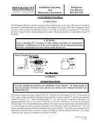
INSTALLATION<br />
CAUTION: DO NOT REMOVE NAMEPLATE OR APPLY ANY COVERING OVER THE LABELS ON THIS UNIT.<br />
Fig. 1 <strong>Installation</strong> of Slip in <strong>Heater</strong><br />
MOUNTING<br />
Step 1 - Cut hole in side of duct 1/8" larger than heater body.<br />
Step 2 - Insert heater body all the way into duct until terminal box covers<br />
opening.<br />
Step 3 - Secure heater in place with sheet metal screws.<br />
Note: For vertical airflow, angle brackets, a maximum of 1" wide,<br />
are recommended inside the duct on both sides to support the<br />
heater when the duct width exceeds 24 inches.<br />
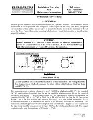
Fig. 2 <strong>Installation</strong> of Flanged <strong>Heater</strong><br />
MOUNTING<br />
Step 1 - Provide flanges on both ends of duct to match heater flanges.<br />
Step 2 - Secure heater flanges to duct with sheet metal screws or bolts.<br />
Note: When flanges are aligned properly, the entire coil section<br />
should be within the air stream.<br />
These heaters are suitable for either vertical up or horizontal airflow with airflow in either direction. Observe instructions on UP label when positioning heater (see<br />
Page 2, Item 7) Note: If mercury contactors or SCRs are built into the heater, it will operate only in the position indicated by the CAUTION label.<br />
In special cases where the heater terminal box is no longer than the heater frame, refer to separate mounting instructions, Bulletin I-139.<br />
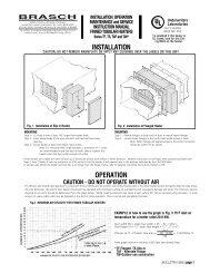
For efficient <strong>and</strong> trouble-free operation it is important that air distribution be uniform over all the heating coils in the entire heated section <strong>and</strong> particularly the area where<br />
the coils terminate. No electric duct heater should ever be operated with insufficient airflow or overheating <strong>and</strong> subsequent damage will result. The minimum velocity<br />
required at any point should be determined from the graph below. NOTE: Heating elements may retain a light surface film die to manufacturing processes. A small<br />
amount of vapor <strong>and</strong>/or odor may be detected at the start of initial operation. This is normal <strong>and</strong> completely harmless.<br />
Fig.3 MINIMUM AIR VELOCITY FOR SLIP-IN AND FLANGED HEATERS<br />
OPERATION<br />
CAUTION - DO NOT OPERATE WITHOUT AIR<br />
EXAMPLE of how to use the graph in Fig. 3 75°F inlet air<br />
temperature for a heater rated 25.0 KW.<br />
<strong>Duct</strong> width (W) = (open face width = 24" - ¾" = 23¼")<br />
<strong>Duct</strong> height (H) = 12" (open face height = 12" - 2½" = 9½")<br />
25.0<br />
KW per sq. ft. of heater face area = (9½) (23¼) = 16.3 KW/Sq. Ft.<br />
144<br />
From graph minimum velocity is 690 fpm (see dotted lines).<br />
*F-Flanged G-Flanged (81°F inlet max.)<br />
S-Slip-in, T-Slip-in (81° F inlet max.)<br />
W-Outdoor use construction<br />
BULLETIN 1-<strong>17</strong>-1 / page 1
HOW NOT TO INSTALL DUCT HEATERS<br />
Electric duct heaters differ from other types of heating coils (such as steam or hot water coils) in that they produce<br />
100% heat as long as the elements are energized, regardless of air flow. Therefore, problems may arise if portions of<br />
the heater are blocked. Listed below are some of the important items to watch when installing any duct heater.<br />
1<br />
2<br />
3<br />
4<br />
5<br />
6<br />
7<br />
8<br />
DO NOT OPERATE WITHOUT AIR<br />
<strong>Heater</strong> should be interlocked with fan (using pressure<br />
type airflow switch or electrical interlock). Do not<br />
energize heaters with remote contactors until thermal<br />
cutout has been connected.<br />
DO NOT OPERATE HEATER WITH INADE-<br />
QUATE AIRFLOW<br />
Refer to Figure 3, Page 1 to obtain minimum velocity<br />
needed to keep heating coils from glowing red <strong>and</strong> to<br />
prevent nuisance tripping of thermal cutout.<br />
DO NOT OPERATE HEATER WITH UNEVEN<br />
AIR DISTRIBUTION<br />
Adequate airflow must be present at all points of the<br />
heater face area. Use of turning vanes or baffles may<br />
be necessary to obtain even air distribution.<br />
AIR MUST BE FILTERED <strong>and</strong> free of combustible<br />
particles <strong>and</strong> hazardous vapors.<br />
LEAVE AT LEAST 48” BETWEEN DUCT<br />
HEATER AND ANY TURN OR ELBOW in<br />
the ductwork <strong>and</strong> between heater <strong>and</strong> heat pumps or<br />
air conditioners. If less than 48" between heater <strong>and</strong><br />
elbow, provide turning vanes <strong>and</strong> order heater with<br />
coils derated to 35W/in 2 . Absolute minimum between<br />
heater <strong>and</strong> elbow is 24".<br />
LEAVE AT LEAST 48” BETWEEN HEATER<br />
AND DUCT TRANSITION. Transitions can be<br />
avoided by specifying a duct heater sized to match the<br />
duct size exactly. If a transition cannot be avoided <strong>and</strong><br />
heater has to be less than 48" from the transition,<br />
transition should conform to the maximum angles<br />
indicated at right.<br />
DO NOT MOUNT HEATER WITH TERMINAL<br />
BOX ON TOP OR BOTTOM OF HORIZONTAL<br />
DUCT because resistance coils will be unsupported<br />
<strong>and</strong> may sag. For applications where electrical<br />
connections must be at bottom, specify UL Listed<br />
bottom insert heater (slip-in) or flanged heater with UL<br />
Listed bottom outlet box.<br />
DO NOT INSTALL HEATER IN HORIZONTAL<br />
DUCT WITH THERMAL CUTOUT AT BOTTOM<br />
ELECTRODUCT heaters can be mounted in any position<br />
in a vertical or horizontal duct except when mounted in<br />
a horizontal duct the thermal cutout must be at the top.<br />
Follow THIS SIDE UP instructions on heater.<br />
NOTE: If mercury contactors or SCRs are built into the<br />
heater, install only in the position indicated by the<br />
CAUTION label.<br />
690 fpm<br />
700 fpm<br />
450 fpm<br />
250 fpm<br />
BULLETIN 1-<strong>17</strong>-1 / page 2
9<br />
10<br />
11<br />
12<br />
13<br />
DO NOT INSTALL STANDARD HEATER IN<br />
DUCTS WITH INTERNAL OBSTRUCTION<br />
GREATER THAT 1”because the obstruction may<br />
block airflow near coil terminations, cutout <strong>and</strong> heat<br />
limiters, instead, use a special slip-in heater with<br />
recessed terminal box <strong>and</strong> reduce frame size or a<br />
flanged heater with face area equal to inside duct<br />
dimensions <strong>and</strong> extra wide flanges.<br />
NOTE:<br />
For heaters used in air conditioning ducts in<br />
areas of high relative humidity, specify insulated<br />
terminal box to prevent condensation.<br />
DO NOT INSULATE EXTERIOR OF TERMINAL<br />
BOX.<br />
Terminal box must not be externally insulated or<br />
blocked in any way. Use heaters with factory-installed<br />
insulation on duct side of terminal box.<br />
DO NOT INSTALL STANDARD HEATER where<br />
face area may be blocked by frame members, filters,<br />
filter supports, insulation cooling coil headers, blower<br />
scrolls or any other kind of obstruction. Use recessed<br />
terminal box <strong>and</strong> order heater with no coils three to<br />
four inches from top, bottom or back flange.<br />
NOTE:<br />
Derating of coils is no substitute for good air<br />
distribution. Therefore, heater should be<br />
located as far as possible from obstructions<br />
in airstream.<br />
DO NOT INSTALL HEATER NEAR DUAL<br />
OUTLET BLOWER since there will be little or no<br />
airflow across area between dual outlets. Use individual<br />
heaters for each blower outlet or move heater far<br />
enough (four feet minimum) from dual outlets to assure<br />
good air distribution.<br />
DO NOT INSTALL HEATER CLOSER THAN<br />
FOUR FEET TO FAN unless turning vanes, pressure<br />
plates or other devices are used on the inlet side of the<br />
heater to ensure even distribution of air over the face<br />
of the heater (NEC424-59)<br />
HORIZONTAL DUCT (TOP VIEW CUTAWAY)<br />
14<br />
15<br />
16<br />
<strong>17</strong><br />
HEATER IN SERIES - Two heaters can be installed in series proving:<br />
a) the leaving air temperature of the first heater does not exceed 100ºF<br />
b) both heaters have a minimum air velocity according to the graph, Figure 3, Page 1, <strong>and</strong><br />
c) the downstream heater is a Type F or S <strong>and</strong> so located that it will not "see" the upstream heater; thus, the<br />
upstream heater can be in the main duct <strong>and</strong> the downstream heater can be in a branch duct. Where both<br />
heaters are in the same duct, a minimum distance of five feet between heaters is required.<br />
LONG HEATERS - It is recommended that heaters with W Dimensions greater than 72" be ordered with a linear thermal cutout.<br />
The sensing element of the linear cutout extends the entire length of the heater <strong>and</strong> turns the heater off when a hot spot develops.<br />
When hot spot has cooled, heater resumes normal operation.<br />
DO NOT CONNECT ALUMINUM SUPPLY WIRES to st<strong>and</strong>ard duct heater. <strong>Heater</strong> must be ordered with special line<br />
terminals suitable for aluminum conductors <strong>and</strong> sized to accept the larger gauge required.<br />
DO NOT INSTALL STANDARD HEATER OUTDOORS - if heater will be subject to weather, specify raintight construction.<br />
18<br />
DO NOT BUNDLE, TIE OR WRAP POWER WIRING IN GROUPS as this may cause overheating <strong>and</strong> eventual breakdown<br />
of insulation.<br />
BULLETIN 1-<strong>17</strong>-1 / page 3
WIRING INSTRUCTIONS<br />
DISCONNECT ALL POWER SOURCES before doing any work on the heater installation.<br />
Follow the wiring diagram located on inside of terminal box cover. If there is more than one heating step, wire the unit so the steps are energized in the<br />
same sequence as numbered in the heater. If the heater does not have a built-in disconnect switch or main circuit breaker, install a remote disconnect<br />
in accordance with the National Electric Code Articles 424-65 <strong>and</strong> 424-19.<br />
The fan must be interlocked with the heater so that the heater is not energized unless the fan is on. UL Listed heaters have a fan interlock either<br />
built-in or furnished as part of a separate UL Listed assembly. If remote contractors are employed, they must have adequate ratings <strong>and</strong> be UL Listed for<br />
100,000 cycles of operation. Do not exceed the control circuit volt-ampere rating shown on the nameplate. These contractors must be supplied by <strong>Brasch</strong><br />
Manufacturing Company for a UL Listed heater. Use NEC Class 1 wiring for the control circuit as described in Article 725 of the National Electrical Code.<br />
Before placing heater in operation, make sure all terminal connections are tight. It is recommended that all terminals be re-tightened after the first 24<br />
hours of operation <strong>and</strong> checked for tightness at least once each year thereafter.<br />
MAINTENANCE<br />
<strong>Brasch</strong> heaters are made with the finest components available, tested by a trained quality control engineer <strong>and</strong> should not normally require maintenance<br />
except for periodic tightening of terminals (see Wiring) Associated equipment, however, may require periodic cleaning, adjustment or calibration.<br />
Maintenance of associated equipment should be performed in accordance with manufacturer's specifications.<br />
SERVICE INSTRUCTIONS<br />
All ELECTRODUCT heaters are equipped with double safety protection (automatic reset thermal cutout usually in the control circuit <strong>and</strong> heat limiters<br />
<strong>and</strong>/or manual reset thermal cutouts in the power lines). <strong>Heater</strong> may also have optional additional safety devices. Safety devices should not be replaced<br />
without first correcting the problem causing them to open the circuit. Additional instruction manuals covering specific components will be supplied with<br />
any built-in equipment other than the st<strong>and</strong>ard thermal cutouts. DISCONNECT ALL SOURCES OF POWER BEFORE SERVICING EQUIPMENT.<br />
LOCATING TROUBLE<br />
1<br />
2<br />
3<br />
PROBLEM<br />
HEATER<br />
WILL NOT<br />
OPERATE<br />
HEATER CYCLES<br />
(WILL NOT<br />
STAY ON)<br />
IMPROPER<br />
TEMPERATURE<br />
REGULATION<br />
POSSIBLE SOLUTION<br />
Recheck installation instructions (page 2 & 3) <strong>and</strong> wiring diagrams to be sure equipment has been installed according to<br />
manufacturer's recommendations.<br />
Disconnect switch or main circuit breaker may be in "OFF" position. If heater has built-in disconnect switch, door must<br />
be closed <strong>and</strong> switch turned ON" before heater will operate.<br />
If the fan <strong>and</strong> heater are interlocked with a fan relay, the fan must be on before the heater will operate. If an airflow switch<br />
is used, air pressure in the duct must be sufficient (at least .07" WC) to close the switch before the heater will operate.<br />
Automatic (or manual) reset thermal cutout (see Form I-12) may have opened when overheating resulted from insufficient<br />
airflow or poor air distribution. Allow heater temperature to return to normal so that automatic thermal cutout may reset<br />
or manual reset thermal cutout may be reset. Correct cause of overheating before proceeding.<br />
Heat limiter(s) may have opened if local "hot spot" developed or if automatic reset thermal cutout failed to open first,<br />
when overheating occurred. Correct cause of overheating <strong>and</strong> replace heat limiter (see Form I-12).<br />
Check main fuses. If open correct cause of failure before replacing fuses.<br />
Check air inlet <strong>and</strong> discharge openings for obstructions. See that filters are not clogged, fire dampers are open <strong>and</strong> air<br />
system is balanced.<br />
Check to see that the heater terminal box is tight against duct <strong>and</strong> heater safety devices are receiving sufficient air flow.<br />
Air flow must be distributed evenly over entire face area.<br />
Look at heater coils in operation (through observation port in duct); any red area is not receiving enough air (A small<br />
amount of redness is permissible inside the coil insulating bushings.) Refer to minimum air flow graph (Fig. 3) for air flow<br />
requirements <strong>and</strong> make sure that air flow through every part of the heater is sufficient. <strong>Coil</strong>s must not glow.<br />
If air flow switch is used, contactors may "chatter" if airflow is not sufficient to keep switch fully on.<br />
If duct has internal insulation, the insulation may be blocking the safety devices (see Page 3, Item 9).<br />
Recheck installation instructions (pages 2 & 3) <strong>and</strong> wiring diagrams to be sure equipment has been installed according to<br />
manufacturer's recommendations.<br />
Make sure associated control equipment, such as thermostats, are in the correct location <strong>and</strong> that all controls are<br />
adjusted according to manufacturer's specifications for existing field conditions.<br />
Check air system balance to see that correct amount of airflow is supplied for proper zone control.<br />
Automatic thermal cutout may be opening (cycling) before room thermostat is satisfied. (See 2 above).<br />
Insufficient heat may be caused by:<br />
A. <strong>Open</strong> heat limiter(s) or thermal cutout. B. Incorrect supply voltage. C. <strong>Heater</strong> too small (in wattage)<br />
for application.<br />
BRASCH LIMITED WARRANTY<br />
<strong>Brasch</strong> Manufacturing Company, Inc. warrants heater resistance coils against defects in material <strong>and</strong> workmanship for a period of two years from<br />
the date of shipment. Other components <strong>and</strong> accessories are guaranteed, for a period of one year from date of shipment, against defects in<br />
material <strong>and</strong> workmanship. Should evidence of defects in material or workmanship occur during the warranty period, <strong>Brasch</strong> Manufacturing<br />
Company, Inc. will repair or replace the heater, at its own discretion, without charge. <strong>Brasch</strong> Manufacturing Company, Inc. shall not be held<br />
responsible for any charges in connection with the removal or replacement of allegedly defective equipment; nor for incidental or consequential<br />
damage. This warranty does not apply to damage from accident, misuse or alteration. Also, this warranty does not apply where the connected<br />
voltage is more the 5% above product nameplate voltage, nor to equipment that has been improperly installed, wired or maintained.<br />
BULLETIN 1-<strong>17</strong>-1 / page 4