View - Stoves Online
View - Stoves Online
View - Stoves Online

You also want an ePaper? Increase the reach of your titles
YUMPU automatically turns print PDFs into web optimized ePapers that Google loves.
GUARANTEE<br />
08/08<br />
CONDITIONS OF GUARANTEE<br />
Your ESSE stove is guaranteed against defects arising from faulty manufacture for two years subject to<br />
the following express conditions. Failure to comply with these conditions will invalidate the guarantee.<br />
• Your ESSE dealer or a suitably qualified engineer must install the stove. Upon installation the receipt<br />
must be kept as proof of purchase.<br />
• The guarantee is one year from date of purchase.<br />
• The guarantee does not cover parts deemed to be replaceable in the normal usage of the stove.<br />
These parts are listed below:<br />
All Models: glass panels, rope seals, glass seals.<br />
Solid Fuel Models: bottom grate or firebars, ashpan, firebricks, cast iron liners, riddling lever, baffle plate,<br />
log guard.<br />
Natural Gas or L.P.G Models: Ceramic coals and matrix, TTB switch.<br />
Boiler Models: boilers are guaranteed against weld failure. Appropriate precautions must be taken to<br />
prevent internal corrosion.<br />
INTERMITTENT USE OF YOUR STOVE - ENAMEL STOVES ONLY<br />
In the event of intermittent use and prolonged shutdown, it should be noted that in some circumstances<br />
enamel might be displaced due to ingress of damp. Whilst this is rare, it is most likely to occur in<br />
situations where the unused stove remains in an unheated property. There is a layer (known as the<br />
groundcoat) between the vitreous enamel surface and the cast iron. Groundcoat is porous and if exposed<br />
(e.g. after a chip in the vitreous enamel coat), may allow damp to penetrate behind the vitreous enamel<br />
and spread through the groundcoat. Surface oxidisation of the cast iron may thereafter occur, causing<br />
the vitreous enamel coating to fall off. Such damage will not be covered by your warranty. We<br />
recommend that a light coating of petroleum jelly be applied to any damaged areas when the stove is not<br />
in use to help to keep out the damp.<br />
HOW TO PROCEED WITH A COMPLAINT<br />
If you have cause for dissatisfaction with your stove, you should first contact your ESSE dealer who will,<br />
bring your concerns to our attention. We will assess the nature of the complaint and either send<br />
replacements parts for your dealer to fit, or nominate a regional engineer to inspect the appliance and<br />
carry out any remedial work that may be necessary. If the fault is not actually due to faulty manufacture<br />
but some other cause i.e. misuse, failure to install correctly, or failure to service at regular intervals, a<br />
charge will be made to cover the cost of the visit and any new parts required.<br />
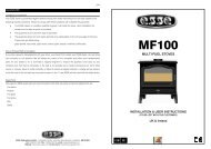
100/200/700<br />
MULTI-FUEL STOVES<br />
INSTALLATION & USER INSTRUCTIONS<br />
(TO BE LEFT WITH THE CUSTOMER)<br />
UK & Ireland<br />
ESSE Engineering Limited, Ouzledale Foundry, Long Ing, Barnoldswick, Lancashire BB18 6BN<br />
Tel: 01282 813235 Fax: 01282 816876 Website: http://www.esse.com<br />
ESSE Engineering Limited, Ouzledale Foundry, Long Ing, Barnoldswick, Lancashire BB18 6BN<br />
Tel: 01282 813235 Fax: 01282 816876 Website: http://www.esse.com<br />
GB IE
CONTENTS<br />
General Safety Notes Page 2<br />
Chimney & Flue Page 3<br />
Flue Draught Page 5<br />
Dimensions & Clearances Page 6<br />
Installing the Stove Page 6<br />
Operating Instructions Page 8<br />
Woodburning Page 8<br />
Solid Mineral Fuel Burning Page 10<br />
Maintenance Page 11<br />
Guarantee Page 12<br />
• These instructions give a guide for the installation of the appliance but in no way absolves the installer<br />
from responsibilities to confirm to British Standards, in particular BS8303 and BS6461, relating to the<br />
installation of solid fuel appliances. The installation should also comply with local Building Regulations<br />
and Local Authority Bye-Laws.<br />
• The stove must be placed at least 40cm away from any combustible materials. If necessary, any<br />
adjoining walls should be protected from the effects of heat.<br />
CHIMNEY & FLUE<br />
GENERAL SAFETY NOTES<br />
• Properly installed, operated and maintained, this appliance will not emit fumes into the dwelling.<br />
However occasional fumes from de-ashing and re-fuelling may occur. Persistent fume emission is<br />
potentially dangerous and must not be tolerated. If fume emission does persist, open doors and<br />
windows to ventilate the room. Let the fire burn out or eject and safely dispose of fuel from the<br />
appliance. Once the fire is cold, check the flue and chimney for blockages and clean if required. Do<br />
not attempt to relight the fire until the cause of the fume emission has been identified and corrected.<br />
Seek expert advice if necessary.<br />
• Do not fit an extractor fan in the same room as the appliance.<br />
• An adequate air supply for combustion and ventilation is essential. Air openings provided for this<br />
purpose must not be restricted.<br />
• It is important that flue ways are cleaned frequently and the chimney swept regularly. Also the stove<br />
must be maintained in good mechanical order. Regular sweeping means at least once per year for<br />
smokeless fuel and a minimum of twice per year for other fuels.<br />
• If the chimney was previously used for an open fire, it is possible that the higher flue gas temperatures<br />
generated by the stove may loosen deposits that were firmly adhering to the inner surface of the<br />
chimney and cause blockage of the fluepipe. We recommend that in such a situation a second<br />
sweeping of the chimney should be carried out within one month of regular use of the stove after<br />
installation. Also, lock or remove any existing dampers in the flueway.<br />
• Should it be likely that children, aged or infirm people approach the fire, then a fireguard should be fitted.<br />
• Avoid the use of aerosol sprays in the vicinity of the stove when it is in operation.<br />
• The installer has a responsibility under the Health and Safety at Work Act 1974 to provide for the safety<br />
of persons carrying out the installation. Attention is drawn to the fact that fire cement is caustic and<br />
hands must be washed thoroughly after use. The appliance is heavy and care must be taken during<br />
handling. Although the appliance does not contain asbestos products, it is possible that asbestos may<br />
be disturbed in existing installations and every precaution must be taken.<br />
The successful operation of these appliances relies on the adequate performance of the chimney to which<br />
it is connected. The chimney must:<br />
• Have an internal cross section of no less than 320 cm.sq (200mm Dia.). (If a flue liner is used it should<br />
be 5” diameter, for 100 and 200 stoves, 6” diameter for the 700 stove and suitable for solid fuel).<br />
• Be a minimum 4.6m high from hearth level to pot.<br />
• Be terminated at least 1m above roof level so that the chimney does not terminate in a pressure zone.<br />
See Fig.2<br />
• Be free from cracks, severe bends, voids, and obstructions.<br />
• Be connected to this one appliance only.<br />
• New chimneys must be built in accordance with local building regulations.<br />
• Existing chimneys must be tested in accordance with HETAS requirements.<br />
• If the stove is installed as a freestanding appliance, it should not support any part of the chimney.<br />
• Voids in the chimney should be avoided, as these will prevent a steady flue draught.<br />
• The stove flue pipe should pass beyond the narrowing of the chimney. See Fig.1<br />
• Consideration should be given to falling soot. For rear outlet stoves it may be necessary to provide a<br />
soot catchment area in the flue pipe so that soot does not settle in the path of the flue gases. The<br />
optional rear flue box attachment available from ESSE has a detachable base that allows for fallen soot<br />
to be removed. See Fig.1.<br />
• A flue/chimney access point may also be required so that the state of the chimney can be checked<br />
and any fallen soot removed.<br />
• External flues must be insulated to prevent heat loss.<br />
2 3
Fig.1 - Ideal Flue Connections. Optional rear flue box attachment is for use with the 100 / 200 stoves only<br />
Flue liner<br />
Insulation<br />
Flue access for<br />
cleaning inspection<br />
Closure plates<br />
(preventing voids)<br />
FLUE DRAUGHT<br />
The chimney can be checked, before the stove is installed, with a smoke match. If the chimney doesn’t pull the<br />
smoke it may suggest the chimney needs attention (see the Flue Diagnosis Table, below).<br />
Measurements<br />
The flue draught test hole must be drilled in the flue pipe as close to the stove as possible and before any<br />
flue draught stabiliser.<br />
Note: This test is only a guide as an apparently poor flue may improve once the stove is installed, lit and<br />
the flue is warmed. If, once the stove is installed, there is any doubt that the chimney is providing an<br />
adequate draught, a flue draught reading can be taken with the stove lit. Two flue draught readings<br />
should be taken, one with the stove at minimum firing rate and one at maximum firing rate.<br />
Fig.2 - Chimney and Flue Performance<br />
Optional rear flue box<br />
attachment with<br />
detachable base for<br />
removing fallen soot.<br />
Available from ESSE.<br />
Minimum<br />
The stove should be lit and allowed to warm the flue thoroughly. The air controls can then be set so that<br />
the stove burns on a low setting. Allow the burning rate to become steady. The flue draught reading should<br />
now be taken with the primary air intake closed and the airwash control fully open.<br />
Maximum<br />
The primary air intake can now be opened to allow the stove to burn at maximum rate. Give the stove<br />
some time for the burning rate to become steady and then close the primary air intake, make sure the<br />
airwash control is fully open and take a flue draught reading immediately.<br />
Ideally, the flue draught readings should range between 1mm wg and 2.5mm wg. Any readings<br />
significantly outside this range may indicate the need for remedial action.<br />
Pressure and suction<br />
zones created by<br />
wind flow<br />
WIND<br />
WIND<br />
WIND<br />
Low flue draught symptoms: difficult to light and smoke coming into the room.<br />
Cause<br />
Remedy<br />
Cold chimney<br />
Line the chimney<br />
Chimney too short<br />
Extend the chimney<br />
Position of<br />
chimney outlets<br />
The effect of<br />
adjacent buildings,<br />
hills, & trees on the<br />
exit of flue gases<br />
NOT LESS THAN 1M (39”)<br />
WITHIN 2.3M (90”)<br />
NOT LESS THAN<br />
600MM (23.5”)<br />
WIND<br />
NOT LESS THAN 1M (39”)<br />
SKYLIGHT<br />
WITHIN 600MM (23.5”)<br />
WIND<br />
NOT LESS<br />
THAN 10”<br />
NOT LESS<br />
THAN 1M (39”)<br />
WIND<br />
Down draught<br />
Chimney diameter too large<br />
Chimney obstruction<br />
Restricted air supply<br />
Relocate/extend chimney terminal. Fit an anti down draught cowl<br />
Line the chimney<br />
Clear/sweep the chimney<br />
Check for competing draughts (other chimneys, extractor hoods/fans).<br />
Fit an air vent if the room is sealed.<br />
High flue draught symptoms: fire difficult to control, fuel will not last, stove too hot, stove damage, chimney fire.<br />
Cause<br />
Remedy<br />
External wind conditions combined Fit stabilizer cowl. Fit flue draught stabilizer.<br />
with chimney terminal<br />
FLUE STABILIZER<br />
A flue stabilizer can be fitted to reduce the draught through the stove if the flue draught is too high.<br />
The flue stabilizer should be:<br />
• fitted in the same room as the stove • the same size as the flue pipe<br />
• fitted no closer than 700mm to the flue outlet of the appliance.<br />
4 5
305 130<br />
06<br />
499<br />
DIMENSIONS & CLEARANCES (all measurements are in mm)<br />
305 130<br />
630<br />
630<br />
596<br />
500<br />
610<br />
428<br />
310 267<br />
Fig.3<br />
900<br />
500<br />
600<br />
20 170<br />
600<br />
690<br />
520<br />
Clearances from combustibles:<br />
A: Sides 400 B: Top 450 C: Rear 400 D: Front 305<br />
170<br />
485 900<br />
140 190<br />
20<br />
90<br />
310<br />
430<br />
520<br />
600<br />
595<br />
460<br />
595<br />
485<br />
165<br />
Important Installation Notes:<br />
1. The installation must allow for adequate chimney sweeping.<br />
2. Avoid using bends greater than 45° to the vertical. All flue pipe sections should be as close to vertical as possible.<br />
165<br />
3. All joints in the flue system must be effectively sealed.<br />
4. All flue sockets must face upwards.<br />
On completing the installation, check that all the internal components of the stove are positioned correctly.<br />
140<br />
265<br />
535<br />
Check - ash pan, iron grate, baffle, side and back bricks, coal bar.<br />
535<br />
310<br />
Fig.4 - Arranging the flue plug for top or rear outlet for 100 / 200 <strong>Stoves</strong><br />
610<br />
310<br />
485<br />
140<br />
190<br />
485<br />
140<br />
265<br />
305 130<br />
320<br />
268<br />
90<br />
Flue plug<br />
Gasket<br />
Clamping bar<br />
385<br />
585<br />
630<br />
800<br />
305 130<br />
700<br />
620<br />
268<br />
500<br />
630<br />
544<br />
610<br />
370<br />
350<br />
500<br />
620<br />
485<br />
640<br />
187<br />
372<br />
390<br />
544<br />
Convector<br />
Panel<br />
INSTALLING THE STOVE<br />
Rear flue<br />
Collar<br />
610<br />
350<br />
485<br />
187<br />
372<br />
Positioning<br />
The overall dimensions of these stoves are shown in Fig.3. Fig.3 shows recommended distances between<br />
the stove and surrounding combustible materials. As a rule, any surrounding combustible material should<br />
not exceed 80°C. There should be sufficient space around the stove for service work.<br />
Hearth<br />
The construction of the hearth must conform to Building Regulations, must be firm, non-combustible and<br />
capable of supporting the stove.<br />
Fig.5 - Using the stove mitt<br />
Rear flue<br />
blanking plate<br />
Airwash control (secondary air)<br />
Fig.6a - 700 Stove<br />
Flue Connection - 100 & 200 <strong>Stoves</strong><br />
The flue pipe used to connect the stove to the chimney is 5” (125mm) in diameter. The stove is supplied<br />
Opening the door<br />
ready for top flue connection. To change to rear connection the flue blanking plug supplied with the stove<br />
is used to block the top flue outlet. The blanking plug in the rear flue connection must then be removed<br />
(to access the bolts attaching the rear flue connection the convector panel must first be removed), see<br />
Fig.4. A rear flue box attachment is also available from ESSE that allows the stove to be installed further<br />
out of any building recess. Fig.1 shows suitable flue connections.<br />
Primary Air Control<br />
Fig.6b - 700 Stove<br />
Flue Connection - 700 Stove<br />
The flue pipe used to connect the stove to the chimney is 5” (125mm) in diameter. The stove is supplied<br />
ready for top flue connection. Fig.1 (left hand side illustration only) shows suitable flue connections.<br />
primary air control.<br />
Anti-clockwise to open.<br />
Secondary Air Control<br />
6 7
OPERATING INSTRUCTIONS<br />
Your Stove<br />
Fig.5, 6a & 6b shows the stove and it’s controls.<br />
Additional loose parts supplied inside your stove include:<br />
• A stove mitt is provided - for removing the ash pan, adjusting the primary air control, adjusting the<br />
air wash control, and operating the door handle. Fig.5 shows how the stove mitt is used.<br />
• A flue blanking plug to blank the top flue outlet if the rear flue outlet is to be used (100 / 200 <strong>Stoves</strong> only).<br />
WOODBURNING<br />
Lighting & Controlling the Fire<br />
Before lighting the fire for the first time ensure that the baffle, the side and back bricks and all the internal<br />
components are in position.<br />
Open the air wash control and the primary air control fully. Place some tightly rolled paper on top of some<br />
crumpled paper on the base towards the back of the stove. On top of this, place some small pieces of<br />
wood. Light the crumpled paper and close the door. Once the fire becomes established add some larger<br />
pieces of wood. As the stove comes up to temperature close the spinner. The burning rate of the stove<br />
can now be regulated by the rate at which fuel is added and by adjusting the air wash control.<br />
With the above in mind it is plain to see that the stove should ideally be run with the primary air inlet closed<br />
and the air wash control open whenever possible. Another advantage of running the stove with the air<br />
wash open is that the air being drawn into the stove travels across the glass forming an air barrier between<br />
the glass and the fire bed helping to prevent smoke particles sticking to the glass. If the fire dies down<br />
too low, opening the primary air control for a short period will revive it.<br />
700 Stove<br />
When burning wood, start a small fire with firelighters and small, dry kindling. Both the Primary and<br />
Secondary air should be fully open. It may be necessary to crack open the doors to allow additional air<br />
through the stove until the fire is established. Gradually add further logs and close the Primary air. The<br />
fire may now be controlled with the Secondary air control.<br />
Note: Wood burns most efficiently when the air for combustion is supplied from above the fire bed<br />
rather than below. The air supplied above the fire bed provides the oxygen necessary for the volatile<br />
gases (smoke), given off by the wood as it heats, to combust. This ensures that the gases are burnt<br />
and used to heat the stove instead of being wasted up the chimney or condensing and forming tarry<br />
deposits inside the stove, in the flue or on the stove glass. Running the stove with the primary air control<br />
open and the air wash control closed will provide oxygen for the wood to burn on the fire bed but will<br />
not provide air for the volatile gases above the fire bed to combust resulting in a smoky inefficient fire.<br />
Correct running temperatures for wood burning<br />
To get the best results from your stove it is recommended that a wood stove thermometer (available from<br />
your stove dealer) be fitted to the flue pipe above the stove, at eye level if possible. The figures below<br />
show the recommended temperature of the flue gases:<br />
115 °C - 245°C (240°F – 475°F)<br />
The flue gases should be in this temperature band for the safest, most efficient and most economical<br />
operation of your stove.<br />
Below 115°C (240°F)<br />
This is below the condensation point of wood gases and may cause the build up of tar in the chimney,<br />
dirty the stove glass and result in the inefficient burning of fuel.<br />
Above 245 °C (475°F)<br />
Too hot. Heat will be wasted up the chimney. Excess heat may damage the stove or ignite an existing<br />
accumulation of tar resulting in a chimney fire.<br />
Extended burning<br />
Loading a large amount of wood into the stove all at once will reduce the temperature inside the stove.<br />
If the temperature is too low, the gases given off from the wood will be too low to combust resulting<br />
in a lot of smoke covering the inside of the stove, including the glass, with soot. To combat this<br />
problem it is a good idea to increase the temperature of the stove before loading by further opening<br />
the air inlets. Load the wood and leave the air controls open until the moisture is driven out of the wood<br />
and the stove is back up to an efficient operating temperature. The air inlets can then be reduced to<br />
hold the temperature of the stove. Loading the stove little and often will help keep the stove<br />
temperature steady. When loading wood, make sure that the end grain of the wood in the stove is<br />
pointing away from the glass otherwise the moisture and gases coming from the end grain of the<br />
wood will dirty the glass.<br />
Note: The above text should be used as a guide only. The ideal operation of your stove depends<br />
on a number of factors, which vary with each installation, and so gaining experience operating<br />
your stove is the only way to learn its best operation.<br />
Types of Wood for Fuel<br />
For best results use well seasoned hardwood such as Oak, Ash, or Beech. Allow wood to dry out under<br />
cover in well-ventilated conditions for at least twelve months. Wood is ready for burning when radial cracks<br />
appear in the end of the logs. Burning wood that is not seasoned will result in tar being deposited in the<br />
stove, on the glass and in the flueways. This build up of tar is a hazard and if it ignites may cause a<br />
chimney fire. Resinous softwood burns well and gives a high output for short periods but is not as efficient<br />
and does not last as long as hardwood.<br />
Peat<br />
Peat is a fuel conveniently available in some areas and should be burned in the same manner as wood.<br />
8 9
SOLID MINERAL FUEL BURNING<br />
Note: 200 <strong>Stoves</strong> Only 1) Remove cast iron grate 2) Remove the steel grate 3) Replace the cast iron grate.<br />
Note: 700 Stove Only 1) Remove steel plate on top of grate.<br />
Lighting and Controlling the Fire<br />
Before lighting the fire for the first time ensure that the baffle, and the side and back bricks are in position.<br />
Burning without either will result in the stove castings overheating and being damaged.<br />
Open the air wash control and the primary air control fully. Place some tightly rolled paper on top of some<br />
crumpled paper on the base towards the back of the stove. On top of this, place some small pieces of<br />
wood and on top of that a few small pieces of mineral fuel. Light the crumpled paper and close the door.<br />
Once the fire becomes established and the fuel is burning, more fuel can be added. When the stove is<br />
hot and the fuel is no longer producing smoke, the air wash control can be reduced. The burning rate of<br />
the fire can now be controlled with the spinner. As air from the spinner flows up through the grate it will<br />
cool the grate bars preventing them from overheating and becoming damaged. Reducing the spinner air<br />
inlet and introducing air only from the air wash will allow the fuel to burn but the grate will not be cooled<br />
resulting in damage to the grate bars. When controlling the fire, the spinner should be altered gradually.<br />
Reducing the primary air dramatically and all at once on a hot stove will cause the fuel to clinker and will<br />
result in a build up of gases and smoke which could ignite with a bang the moment air is reintroduced.<br />
700 Stove<br />
When burning a solid mineral fuel, start with a small fire of dry wood and firelighters. Once burning well,<br />
add a little solid fuel and keep adding to establish the desired firebed. Start with the primary air control<br />
fully open, and once the bed of coals are burning enough, regulate the fire by closing the Primary air to<br />
the required setting.<br />
Initially the Secondary air should be fully open, but once the fire is burning cleanly, this can be closed and<br />
remain closed.<br />
MAINTENANCE<br />
Grate Bars<br />
The grate bars in the centre of the stove will wear more quickly than the ones at the edges. To ensure even wear,<br />
swap the positions of the grate bars occasionally.<br />
Mineral Fuels<br />
Ordinary bituminous house coal is not recommended and must not be burned in smoke control areas.<br />
Burning bituminous house coal will result in a sooty stove and chimney, and the stove glass will require<br />
cleaning regularly. There are numerous natural anthracites and manufactured smokeless fuels that will<br />
burn cleanly and have more reliable burning characteristics. A list of these fuels and their suitability is<br />
produced by HETAS (www.hetas.co.uk). Consult your local fuel merchant to find out what is available in<br />
your area. Petro-coke should not be used as it burns very hot and may damage the stove castings.<br />
Cleaning the Stove<br />
The stove should only be cleaned when it is cold. The exterior can be dusted with a firm brush.<br />
Do not use a cloth, as this will drag on the paint finish leaving lint on the surface. From time to time it may<br />
be necessary to renovate the exterior by repainting. High temperature stove paints in aerosol form are<br />
available from your stove dealer. Do not use this form of paint until the stove is cold and always read the<br />
instructions on the container before starting to paint. The door glass is made of a special heat resisting<br />
ceramic and may be cleaned when cold with proprietary glass cleaning liquids and a dry cloth.<br />
Shutting Down the Stove (Long Term)<br />
The following procedure should be followed if the stove is not to be used for a long period, summertime for<br />
instance. Remove all the ashes from the grate and ash pan and use a vacuum cleaner nozzle to clean ash<br />
from the base of the stove. Remove the baffle plate and brush the flue ways. Close the door and open the<br />
air inlets fully. This action will allow air circulation through the flue ways and help to avoid corrosion and<br />
condensation.<br />
Extended Burning<br />
Before adding a large amount of fuel, the grate should be de-ashed and the ash pan emptied. Add the<br />
fuel sloping it from the front coal bar up to the back of the stove to the level of the top of the back brick.<br />
Open the primary air inlet and let the fire burn for a period on high rate in order to get the stove back up<br />
to temperature and drive off the moisture and gases in the fuel. If a lot of smoke is produced on reloading,<br />
the air wash control can be opened further to keep the smoke back from the glass. As the fire gets back<br />
up to temperature, reduce the air wash control and reduce the primary air inlet to suit the burning rate.<br />
The exact setting of the air controls depends on a number of variables including; the flue draught, the fuel<br />
used and the installation and so the best settings for your stove can only be learned by experience.<br />
Ash Removal<br />
The level of ash should not be allowed to build up to the level of the grate. If the level of ash becomes too<br />
high the air through the grate will become restricted causing the grate bars to overheat and preventing<br />
the fuel from burning efficiently.<br />
10 11