
Create successful ePaper yourself
Turn your PDF publications into a flip-book with our unique Google optimized e-Paper software.
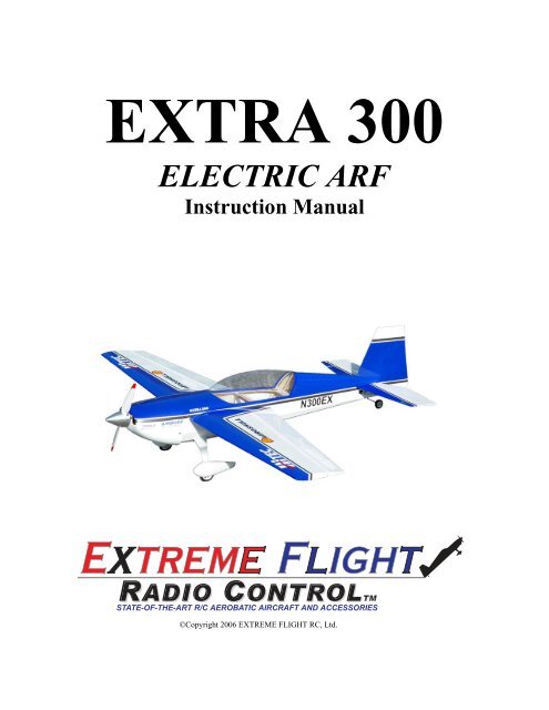
<strong>EXTRA</strong> <strong>300</strong><br />
ELECTRIC ARF<br />
Instruction Manual<br />
©Copyright 2006 EXTREME FLIGHT <strong>RC</strong>, Ltd.
Thank you for your purchase of the <strong>Extreme</strong> <strong>Flight</strong> <strong>RC</strong> 45” Extra <strong>300</strong> Electric ARF. This<br />
aircraft was designed to provide maximum performance and fun in a realistic looking,<br />
lightweight, fully aerobatic park flyer. Using an inexpensive and efficient brushless<br />
outrunner motor and speed controller and a single high discharge 3S1P Lithium Polymer<br />
battery, the Extra <strong>300</strong> provides unlimited performance capability.<br />
Great care was taken to design a light weight yet robust airframe. Expert engineering and<br />
modern laser cutting methods in conjunction with a carbon fiber wing tube and composite<br />
control horns keep weight to a minimum. Unique features such as the ram air equipped<br />
motor box, 2 piece plug in wings, and magnetically retained canopy/hatch make for quick<br />
easy assembly and instantaneous access to the interior of the plane and battery tray. The<br />
Extra <strong>300</strong> can truly be assembled in an evening-buy it one day, fly it the next!<br />
As with all <strong>Extreme</strong> <strong>Flight</strong> <strong>RC</strong> airplanes, the proof is in the flying! Due to the close<br />
proximity of the wing and stab to the thrust line, the Extra <strong>300</strong> is a very neutral flying<br />
aircraft. It flies precision aerobatics remarkably well and allows you to practice your<br />
IMAC sequence almost anywhere. The slightly stretched fuselage makes for a plane that<br />
tracks like a pattern ship and the lightweight wings minimize over rotation in snaps. On a<br />
calm day you’ll be amazed at how well this thing flies the sequences.<br />
If 3D is your thing then strap in! The Extra <strong>300</strong> does it all with ease. Beautiful, slow<br />
high alpha knife edge passes. FLAT spins both upright and inverted, rock solid elevators<br />
and harriers. Tremendous aileron authority and insane roll rate from the massive<br />
ailerons. The Extra does beautiful waterfalls and is capable of performing large round<br />
knife edge loops. You won’t believe how much fun this thing is to fly!<br />
Sport flyers fear not! Just because you’re not a 3D hot dogger or IMAC flyer doesn’t<br />
mean you can’t enjoy the Extra <strong>300</strong>. With reduced rates the Extra <strong>300</strong> is a very easy<br />
plane to fly. Its super light wing loading allows it to land at a walk. It will instill<br />
confidence and allow you to improve your flying skills. When you’re ready for more<br />
advanced aerobatics, flip the dual rate switch and hang on!<br />
As with any high performance aerobatic aircraft, great care must be taken to avoid excess<br />
speed. Excess speed will lead to control surface flutter and quite possibly the complete<br />
destruction of your aircraft. Don’t let this happen to you! Always have the motor at idle<br />
when the airplane is pointed down and reserve full throttle for vertical climbs. Make sure<br />
you have adequate mechanical advantage in your control linkage set-up. If you are<br />
unsure about this, have a more experienced flyer look over your set-up before flying.<br />
<strong>Extreme</strong> <strong>Flight</strong> <strong>RC</strong>, Ltd. in no way warranties its aircraft against flutter. As with all of<br />
our planes, we put the Extra through a rigorous flight testing regime and have not<br />
experienced any control surface flutter.<br />
The Extra was designed around the Torque 2818T/900 Brushless Outrunner motor and<br />
Airboss 35 AMP ESC. This is the best choice for powering the Extra, providing plenty<br />
of power for any maneuver imaginable. Other outrunner motors in this class will work as<br />
well but may require slight modification to the motor mount.<br />
The Extra is very easy to assemble. Take a few minutes to read this manual before<br />
beginning assembly to get familiar with the process.<br />
Let’s get started!<br />
2
Wing assembly<br />
1. Locate a wing panel. Check to see that all hinges are centered between the wing<br />
and aileron. Hold the aileron fully deflected and apply a drop of thin CA to each<br />
hinge. Flip the wing over and repeat.<br />
2. Use a #11 hobby blade to remove the covering over the servo bay. Install the<br />
aileron servo using the manufacturer supplied mounting screws. Route the servo<br />
lead out of the root of the wing.<br />
3
3. Locate the composite aileron control horn, aileron pushrod with z-bend and ezconnector.<br />
Remove the covering over the mounting hole for the control horn with<br />
your #11 blade. Glue the control horn in place with medium CA. Electronically<br />
center your servo and mount the ez-connector to the servo arm. Place the z-bend<br />
in the aileron control horn and the other end of the wire into the hole in the ezconnector.<br />
Center the aileron and tighten the screw in the top of the ez-connector<br />
to retain the aileron pushrod wire. See picture.<br />
4. Repeat for the other wing.<br />
That’s it! You are done with the wings!<br />
4
Fuselage Assembly<br />
1. Lets mount the landing gear first. Locate the aluminum landing gear, (4) 3mm<br />
machine screws ( 2 long, 2 short), (4) wheel collars, the two wheel pants and<br />
wheels and the 2 small plywood squares. Use medium CA to glue the plywood<br />
square to the inside of each wheel pant, centered in the wheel pant opening. You<br />
may need to open the hole in the wheel pant slightly to allow plenty of clearance<br />
for the wheel. Use a drum sanding wheel for this with your moto-tool.<br />
2. Locate the 2 longest 3mm screws and hex nuts. These are the wheel axles. Insert<br />
the screw through the pre-drilled hole in the landing gear and retain with the hex<br />
nut. It would be a good idea to use a drop of blue loc-tite here. Slide one of the<br />
wheel collars onto the axle, followed by the wheel, followed by another wheel<br />
collar. Slide the wheel pant over this assembly before tightening the set screws in<br />
the wheel collars to make sure the wheel is positioned so that it fits in the opening<br />
in the pants. When satisfied, tighten the setscrews in the wheel collars. Position<br />
the wheel pants over the wheels (you will need to slot the wheel pant so that it<br />
will slide down over the axle, again quick work with a moto-tool and proper<br />
attachment). Drill a small hole in the landing gear and into the ply square you<br />
glued into the wheel pants and use one of the small machine screws to secure.<br />
You may also want to put a drop of med CA between the wheel pant and<br />
aluminum gear. The picture below will make this much clearer.<br />
5
3. Apply a drop of loc-tite to each screw and insert it through the landing gear and<br />
into the pre-installed blind nut in the landing gear plate.<br />
6
4. Locate the motor box assembly and the 2 laser cut triangular motor box supports.<br />
Place the tabs in the motor mount assembly into the firewall and push down so that<br />
they lock into place. Install the triangular supports as shown. Wick thin and medium<br />
CA into all joints and allow to cure. Locate the 2 clear plastic air scoops and glue<br />
them into place as shown.<br />
5. Use the manufacturer supplied mounting hardware and mount the motor and ESC<br />
as shown. The hole for the prop shaft may need to be reamed slightly to clear the<br />
C-clip on the motor.<br />
7
6. Position the canopy/hatch in place and slide the cowl over the first former. Use<br />
your spinner (a 2” spinner is the proper size) on the prop shaft to make sure the<br />
cowl is aligned properly. View the cowl from the side and top view to insure it is<br />
positioned properly. When satisfied, secure the cowl in place with a few pieces of<br />
masking tape. Use a small drill bit to drill through the cowl and into the 4<br />
mounting tabs. Secure the cowl with 4 small wood screws included in the<br />
hardware package. I highly recommend that you soak the cowl mounting tabs<br />
with thin CA before drilling.<br />
7. Locate the horizontal stabilizer. Viewing the bottom of the stabilizer, use a #11<br />
blade to remove the covering from the two notches at the leading edge of the<br />
stabilizer. Also remove the covering from the slot for the horizontal stabilizer in<br />
the fuselage. Slide the stabilizer into place and measure from several angles to<br />
insure that it is square to the fuselage and wing. Sand or shim the slot as needed<br />
to insure proper alignment. Use a fine felt tipped marker to make some reference<br />
marks and remove the stabilizer from the plane. Use a hobby knife to remove the<br />
covering from the stab where it will attach to the fuselage to insure a wood to<br />
wood bond. Be very careful not to score the wood which could potentially<br />
weaken the stabilizer. DO NOT GLUE THE STABILIZER IN PLACE YET!!!!<br />
Locate the elevator halves and the carbon fiber joiner tube. Place the elevator<br />
halves on a flat surface and tack glue the carbon tube in place. Check the<br />
alignment, then mix up some 30 minute epoxy and form a fillet between the<br />
carbon tube and elevator halves. This joint is crucial so take your time here.<br />
8
8. After it is dry, flip the elevator over so that the counterbalances are facing the<br />
rear of the plane. Insert the elevator into the slot. Once it is in position, insert the<br />
horizontal stab into place. Re-check alignment and when satisfied, glue the<br />
stabilizer in place with CA or a small amount of epoxy. Once this is dry, slide the<br />
elevator into position and glue the hinges in place with thin CA. Be sure to leave<br />
enough space between the stab and elevator for maximum deflection. Seal the<br />
hinge line on the bottom with Blenderm tape. (DO NOT OMIT THIS STEP!!!)<br />
9. Locate the vertical fin and rudder. Remove the covering from the vertical fin<br />
where it will be glued into the fuselage. Glue the vertical fin in place, making<br />
sure that the trailing edge of the fin is aligned with the rear of the fuselage.<br />
10. Locate the phenolic double rudder control horn. Remove the covering from the<br />
slot near the bottom of the rudder and insert he control horn into the slot. Glue in<br />
place with medium CA or epoxy. Attach the tailwheel assembly as shown in the<br />
9
picture and secure with a small piece of strapping tape. Slide the rudder into<br />
position and glue the hinges in place with thin CA.<br />
11. Locate the elevator control horn and glue in place with medium CA or epoxy.<br />
Use a #11 blade to remove the covering from the elevator servo slot and install<br />
the servo using the manufacturer supplied mounting hardware. Place an ezconnector<br />
on the servo arm. Locate the elevator pushrod and insert the z-bend<br />
into the phenolic control horn and the other end into the ez connector.<br />
Electronically center the servo and then tighten the screw in the ez connector to<br />
clamp down on the pushrod, while making sure the elevator is in the neutral<br />
position. You may need to put a small bend in the pushrod. Pictured is the Hitec<br />
HS-55 sub-micro servo, however we strongly recommend using a stronger servo<br />
if you intend to set-up the Extra for 3D flying. We have had great success with<br />
the Hitec HS-56 and the JR 281.<br />
10
12. Mount the rudder servo as shown inside the fuselage. We highly recommend<br />
using a more powerful servo for the rudder such as the Hitec HS-56, HS-65 or JR<br />
281 to prevent control surface blow back. Use the supplied hardware to assemble<br />
the pull-pull cable system. At the rudder control horn end, the cable will be<br />
threaded through the control horn and secured with a small aluminum tube which<br />
is crimped around the cable. At the servo end, the cable is threaded through the<br />
hole in the connector as shown and then inserted into the ez connector. Center the<br />
servo electronically and make sure the rudder is in the neutral position. Tighten<br />
the screw in the ez connector. Make sure the cables are taut, but not overly tight,<br />
which may cause the servo to bind.<br />
11
10. Install the receiver as shown using Velcro. Use Velcro to secure the battery to<br />
the battery tray and use a Velcro strap around the battery.<br />
11. Use the supplied nylon bolts to secure the wings to the fuselage.<br />
This concludes the assembly of the Extra <strong>300</strong>.<br />
Radio Set-up and flight tips.<br />
CG range for the Extra is from 3.50”- 4.00” from the leading edge of the wing<br />
measured at the wing root. CG should be easy to achieve by moving the battery<br />
along the length of the battery tray. Adjust to fit your flying style.<br />
Control surface recommendations are as follows:<br />
Elevator- 10 degrees low rates, 45+ degrees high rates.<br />
Rudder- 20 degrees low rates, 45+ degrees high rates.<br />
Aileron- 20 degrees low rates, 45+ degrees high rates.<br />
Use exponential function to achieve the best “feel” for your particular flying style. I<br />
highly recommend that you take the time to set up rates for precision flying and<br />
separate rates for 3D. The Extra is capable of flying very precise maneuvers, and<br />
proper rates and CG will allow you to experience this to the fullest extent. Trying to<br />
fly precision aerobatics with 3D rates is an exercise in futility. Spend some time<br />
dialing in and trimming your plane and you will be rewarded with a great flying<br />
experience.<br />
Thanks again for your business!<br />
See you at the flying field!<br />
12