Create successful ePaper yourself
Turn your PDF publications into a flip-book with our unique Google optimized e-Paper software.
<strong>CINEMA</strong> <strong>4D</strong><br />
SPLINES AND EDITS • NURBS TOOLS USE • MODELING TOOLS<br />
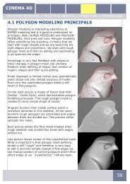
5.1 SPLINES<br />
Cinema has very good toolset for editing splines. Splines are<br />
very useful for creating models. Especially Splines with Nurbs<br />
tools can make work on complicated models much easier. Very<br />
complex curves can be imported from Adobe Illustrator native<br />
format *.AI<br />
Splines are located in menu Objects or with their icons in main<br />
TOOLBAR.<br />
Splines are primarily a sequence of vertices, connected<br />
by lines, lying in 3D space. The shape of these connecting<br />
lines (straight or curved) defines the interpolation.<br />
Apart from the direct connection of the vertices with<br />
straight, rigid lines, there are other kinds of splines that<br />
use an interpolation method where the lines between the<br />
vertices are curved instead of straight. These splines have a soft leading edge without<br />
sharp corners.<br />
The spline itself is infinitely thin. They have some thickness for visibility in a viewport.<br />
A spline is not visible when rendered.<br />
The spline’s line has no three-dimensional depth, even though it occupies<br />
the 3D space. However, many complex 3D objects, among other things, can<br />
be constructed in seconds out of these curves by using them with NURBS<br />
objects.<br />
After the spline is created it can be pulled along its depth in order to make tubelike<br />
objects. You can also rotate a spline around an axis to create objects that have<br />
rotational symmetry, such as wineglasses. Or you can construct a skin over several<br />
splines, with the finished object simulating the contours on a map. More of these<br />
spline-modeling capabilities are discussed in the NURBS section.<br />
To create a new spline curve:<br />
From menu Objects > Spline to create an empty spline.<br />
- Select mode for POINT EDIT and use tool MOVE with icon or from menu<br />
TOOLS<br />
Create points for the spline by Ctrl-clicking in each place where you want to create a<br />
point. The first point defines the start of the spline.<br />
81
<strong>CINEMA</strong> <strong>4D</strong><br />
SPLINES AND EDITS • NURBS TOOLS USE • MODELING TOOLS<br />
• If you Ctrl-click on the curve between two existing points, the new point will be<br />
placed on the spline between the points.<br />
• If you hold down the Shift and Ctrl keys while clicking, the new point will be created<br />
at the beginning of the spline, giving a new starting point.<br />
If the Close Spline option is enabled and you Ctrl-click the starting point, the<br />
spline will be closed.<br />
• Position of curve points can be adjusted with tool MOVE. For multiple selection hold<br />
Shift and LMB.<br />
• The spline is always created in the view of the active viewport. For FRONT VIEW<br />
will be created in XY plane. In TOPVIEW in XZ plane. In the perspective view, the<br />
freehand spline will be created on the plane that is perpendicular to the camera<br />
direction.<br />
For some operations, such as the aligning of objects along a spline (Arrange<br />
command) or the movement of objects along a given curve (Align To Spline tag), the<br />
direction of the spline (where it begins and ends) is important. For this reason, the<br />
spline is color-coded. By default, from the first vertex, the starting point, and<br />
moving outwards, the curve is colored from yellow to orange to red (the end<br />
point). This colored display is visible only when the Points tool is active.<br />
Segments<br />
A spline is made from several partial curves, or<br />
segments. For example, if you create some text, you<br />
will see that only one object is created, even though<br />
you typed in several letters. The text object now<br />
consists of several outlines — one outline or more<br />
per letter. Even when converted to editable it is still<br />
only one object.<br />
For example, the word ‘Test’ consists of four letters;<br />
that makes four separate segments. However,<br />
another, fifth, segment is also present — the inside<br />
of the ‘e’ is a further spline segment. If this type<br />
of element is later extruded to form a 3D object,<br />
<strong>CINEMA</strong> <strong>4D</strong> will automatically punch out a hole that<br />
is the same size and shape of the internal segment of<br />
the ‘e’.<br />
Holes are formed only if a spline lies completely inside another spline and both form<br />
closed curves. If two segments overlap in any way, no 3D object can be formed.<br />
82
<strong>CINEMA</strong> <strong>4D</strong><br />
SPLINES AND EDITS • NURBS TOOLS USE • MODELING TOOLS<br />
Do not confuse the Polygon object with the Spline object. Although both are<br />
essentially just empty containers, the former consists of polygon vertices only while<br />
the latter is made up of spline vertices (and splines).<br />
To create a new spline segment<br />
Add a new point that will be the start point of a new segment (initially, this new point<br />
will be connected to the last point of the previous segment).<br />
Choose Structure > Edit Spline > Break Segment The connection to the<br />
previous segment is now broken. Add further vertices. All new vertices now belong<br />
to the new segment. You can create further segments. If we need first vertex of new<br />
segment to be in the same position as the last vertex of segment created before we<br />
can use move tool. If a spline consists of several segments, then new vertices are<br />
always created from the active vertex. If no vertices are active, then new vertices are<br />
generated at the last-created segment. If several vertices at different segments are<br />
active, new vertices are always generated at the first-created segment.<br />
Attribute manager - Settings for SPLINE<br />
OBJECT PROPERTIES > TYPE<br />
Linear<br />
This simplest of all the spline types connects the vertices,<br />
which define the polygon, with straight, directly connected<br />
lines. You can use these splines to create angular objects<br />
or to simulate sharp jerky movements for animation.<br />
Cubic<br />
This kind of spline has a soft curve between vertices. The<br />
interpolated curve passes directly through the vertices.<br />
Looking at the two points at the top right of the diagram,<br />
you can see that the curve bulges more than is probably<br />
required. This behavior is called overshooting, and it often<br />
appears with closed curvatures. This becomes clearer<br />
when you compare this section of the curve with the same<br />
section of the curve with Akima interpolation.<br />
83
<strong>CINEMA</strong> <strong>4D</strong><br />
SPLINES AND EDITS • NURBS TOOLS USE • MODELING TOOLS<br />
Akima<br />
This spline type creates a soft curve between vertices.<br />
The interpolated curve always passes directly through the<br />
vertices. Overshooting does not happen with this type of<br />
curve.<br />
B-Spline<br />
This kind of spline also creates a soft curve between<br />
the vertices. However, the curve does not pass directly<br />
through the vertices. This produces a very smooth curve.<br />
The vertices control only the approximate path of the<br />
curve. Distant points have less influence on the curve<br />
than those lying closer together. Control points are also<br />
endpoints of tangents of this spline, derivation of shape.<br />
This type of curve belongs to the NURBS.<br />
Bezier<br />
This spline type creates a soft curve path between the<br />
vertices, which can be controlled very precisely. The<br />
interpolated curve always passes through the vertices.<br />
Overshoot does not happen. This interpolation is based<br />
on NURBS geometry, shape is controlled with tangents.<br />
Tangents are in control points and defines force affecting<br />
the shape. Bezier splines are offering the most control.<br />
Working with a Bezier spline and its tangents<br />
If you activate a vertex of the spline (i.e. by clicking on it), additional control points<br />
at the tangents to the curve become visible. With MOVE tool and LMB we can drag<br />
the tangent end point. Changing the direction of the tangent handles controls the<br />
direction of the curve at each vertex. By adjusting the length of these tangent<br />
handles, you can control the strength of the curvature. Drag the tangent end point<br />
towards the vertex point and observe the symmetrical movement of the opposite<br />
handle.<br />
You can change the lengths of the tangents separately<br />
from each other. To do this, Shift-drag a tangent end<br />
point.<br />
You may set different tangent directions on the<br />
right and on the left of the vertex. To do this, Shiftdrag<br />
a tangent end point. With this approach you can<br />
make the otherwise smooth path of a curve produce<br />
sharp corners and peaks.<br />
84
<strong>CINEMA</strong> <strong>4D</strong><br />
SPLINES AND EDITS • NURBS TOOLS USE • MODELING TOOLS<br />
If the tangents of two neighboring points have zero<br />
length, the segment that runs between the vertices<br />
will be linear. Thus, you can mix linear segments<br />
with curved spline shapes.<br />
If you double-click on a Bezier vertex with the<br />
Move, Scale or Rotate tool active, a dialog opens<br />
that allows you to accurately enter both the position<br />
of the vertex (in the spline’s object coordinates) and the position of the tangent<br />
end points (relative to the vertex) numerically. If you convert a Bezier spline to a<br />
different type of spline, all tangent settings will be lost. If a spline is converted from<br />
a non-Bezier type to a Bezier type, all tangents will be assigned default positions and<br />
orientations.<br />
OBJECT PROPERTIES - Close spline<br />
Each spline segment can be closed or open. If<br />
a spline is closed, the start and end points are<br />
connected. There is a big difference between<br />
closing a spline (and interconnecting the start<br />
and end points) and simply positioning the start and end points together. In the first<br />
case, the transition from the start to the end point is soft, in the second case it is<br />
abrupt. To close the spline, Ctrl-click the start point or use option CLOSE SPLINE in<br />
Attribute manager.<br />
INTERMEDIATE POINTS, ANGLE<br />
Here you can define how the spline is further<br />
subdivided with intermediate points. This affects the<br />
number of subdivisions created when using the spline<br />
with NURBS objects.<br />
We will describe two basic modes:<br />
NONE<br />
This method of interpolation locates points only at the<br />
vertices of a spline, using no additional intermediate<br />
points. You cannot enter values into the Number or<br />
Angle boxes.<br />
NATURAL<br />
This interpolation type divides spline by number of<br />
points in number box. The points are positioned closer<br />
together on areas of the spline with more curvature.<br />
You cannot enter values into the Angle box. The<br />
interpolation is not affected by reversing the point order.<br />
85
<strong>CINEMA</strong> <strong>4D</strong><br />
SPLINES AND EDITS • NURBS TOOLS USE • MODELING TOOLS<br />
Create Spline (Curves)<br />
The Spline object allows you to<br />
quickly create new splines from<br />
scratch. However, for some shapes<br />
this approach can be clumsy and<br />
unnecessary. For this reason <strong>CINEMA</strong><br />
<strong>4D</strong> includes spline curves. These are<br />
interactive tools that remain active<br />
until you select another tool, such as<br />
Move. You can thus create any number<br />
of these splines without the need to<br />
select the command each time.<br />
Splines are created in active viewport.<br />
Freehand<br />
You can use this command to draw curves directly in the viewports. Select the<br />
Freehand tool, then click in a viewport and keep the mouse button pressed. You<br />
can then draw the Freehand curve for as long as the mouse button is held down.<br />
Releasing the mouse button will end the Freehand spline creation and the finished<br />
spline will appear. (This is especially useful when tracing patterns with a graphics<br />
tablet.)<br />
• Freehand Splines are always created on the camera plane when you work in the<br />
perspective views, not on the construction plane, which is the case for the Bezier, B-<br />
Spline, Cubic, Akima and Linear splines. If you want to draw a spline onto one plane<br />
(XY, ZY, XZ etc.) you should switch to the corresponding view.<br />
Bezier, B-Spline, Linear, Cubic, Akima<br />
Using these commands, you can create the exact type of curve you require. Choose<br />
the desired spline type. Point editing mode is activated automatically. Click to create<br />
each point. Once you’ve added the desired points, either click the starting point to<br />
close the curve or press Esc to exit the mode. You can then edit the spline in the<br />
usual way (drag to move a point; Ctrl-click to create a new point, etc.).<br />
With these functions we create spline with interpolation. Differences are discussed<br />
at the beginning of this chapter. To end editing press Esc. Other editing functions are<br />
same as for Spline object .<br />
.<br />
• You can alternatively create the points in the same way as for the Spline object.<br />
After choosing the command, rather than clicking to create points, use Ctrl-click<br />
instead; to move a point, drag it; to close the spline, click the starting point<br />
86
<strong>CINEMA</strong> <strong>4D</strong><br />
SPLINES AND EDITS • NURBS TOOLS USE • MODELING TOOLS<br />
5.2 SPLINE PRIMITIVES<br />
<strong>CINEMA</strong> <strong>4D</strong> gives you a generous number of predefined curves. Add to this the<br />
possibility to convert vector based artwork files from other programs (see ‘Vectorizer’)<br />
and to add graphic characters (see ‘Text’) and you have a wealth of spline primitives<br />
at your fingertips. All of these spline primitives are parameterized. This means that<br />
the spline is merely the graphical representation of a mathematical formula built<br />
controlled by parameters you can edit the Attribute manager.<br />
As a result, this mathematical formula initially has no properties to edit within the 3D<br />
viewport. It has no vertices to manipulate. To adjust the vertices with the Points tool,<br />
for example, you must first make the spline editable (Structure > Make Editable).<br />
Then spline is not parameterized anymore and act as normal curve. You can, however,<br />
apply deformer objects or NURBS TOOLS to the spline even if the spline has not been<br />
made editable.<br />
When creating a new spline primitive from the OBJECTS menu, the spline appears in<br />
the viewports and its parameters are displayed in the Attribute manager where you<br />
can set various curve parameters. Let’s try some of them.<br />
Object properties<br />
Common settings<br />
Some of the spline settings are present for each type<br />
of primitive. These common properties are described in<br />
this section.<br />
These settings are PLANE, point order - Reverse<br />
interpolation of curve Intermediate points, Number,<br />
Angle<br />
Use this drop-down list to define in which of the three<br />
planes (XY, XZ, ZY) the spline primitive is to lie. By<br />
default the spline is always positioned so that it is<br />
visible in the current active view.<br />
This means that if the spline is created in the XZ (top) or XY (front) view, then the<br />
spline will be seen, for example, as facing towards the XY plane in the 3D viewport.<br />
In each of the following examples the spline primitive has been created in the frontal<br />
view (XY plane).<br />
87
<strong>CINEMA</strong> <strong>4D</strong><br />
SPLINES AND EDITS • NURBS TOOLS USE • MODELING TOOLS<br />
Reverse<br />
If this option is enabled, the order of the points is reversed. Reversing the points of<br />
the spline primitive not only has an effect after the conversion to an editable spline<br />
curve. The reversal of points also affects commands such as Align to Spline<br />
Intermediate Points, Number, Angle<br />
These interpolation settings define exactly how finely the vertices of a spline will be<br />
positioned. The various choices are described earlier in this chapter.<br />
Some spline primitives<br />
Arc<br />
This command creates arc elements..<br />
Type<br />
With this option you choose the circle element to<br />
be used in your arc. Choose from ARC, SECTOR,<br />
SEGMENT, RING<br />
Radius<br />
Defines the circle radius from which the circular<br />
element is to be created.<br />
Inner Radius<br />
If you set Type to Ring, this defines the inner radius of the ring.<br />
Start / End Angle<br />
Using these two values you can define the start and end point of the arc element. 0°<br />
defines the value as the positive X-axis, 90° the positive Y-axis, 180° the negative<br />
X-axis, etc. These examples assume you are working in the XY plane, as mentioned<br />
earlier.<br />
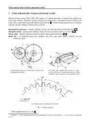
Cogwheel - This command creates a cogwheel.<br />
Teeth - Defines the number of teeth for the<br />
cogwheel.. Minimum value is 5<br />
Inner, Middle, Outer Radius<br />
The overall size of the cogwheel is defined by Outer<br />
Radius, while Inner Radius defines the depth of<br />
the teeth. For avid mathematicians: Depth of teeth<br />
= (outer radius – inner radius). The third value,<br />
Middle Radius, gives the height at which any bevel<br />
will start to take effect<br />
88
<strong>CINEMA</strong> <strong>4D</strong><br />
SPLINES AND EDITS • NURBS TOOLS USE • MODELING TOOLS<br />
5.3 SPLINE EDITS<br />
Tools for editing of curves are located in top menu<br />
Menu > Structure > Edit Spline<br />
• You must first make spline primitive editable<br />
Hard / Soft Interpolation<br />
This command switches all selected points to hard/soft<br />
interpolation. If no points are selected, all points of the<br />
spline are automatically changed to hard interpolation. Hard<br />
interpolation means that the tangents of the appropriate points<br />
are set to a length of zero. Soft interpolation means that the<br />
tangents of the appropriate points are set to a standard length<br />
and direction.<br />
• Could not be applied for B-Spline<br />
Equal tangent length<br />
•This command can be applied to Bezier Splines only. All other types of spline have<br />
preset interpolation which cannot be changed..<br />
For each selected point, the shorter tangent handle is set to the same length as its<br />
partner tangent. If no points are selected, all points are automatically included in the<br />
action.<br />
Equal tangent direction<br />
•This command can be applied to Bezier Splines only.<br />
All other types of spline have preset interpolation which<br />
cannot be changed.<br />
Tangent is usually controlled with the handles for each<br />
control point. If one tangent is not set properly you can<br />
move handle independently with the Shift key to fix this<br />
problem.<br />
Tangents of selected points have same direction so are<br />
forming a line. If no points are selected, all tangents will<br />
have the same direction.<br />
89
<strong>CINEMA</strong> <strong>4D</strong><br />
SPLINES AND EDITS • NURBS TOOLS USE • MODELING TOOLS<br />
Join Segment<br />
A spline can consist of several unconnected segments<br />
(a text spline is a good example of this). If you want<br />
to connect two of these segments, select one or more<br />
points of each segment and use the Join Segment<br />
command. The start points of each spline are joined to<br />
the end points of the other spline. If you directly select<br />
the end points of the two segments, however, these are<br />
also joined. If these end points have the same position,<br />
one of them will be deleted when joining.<br />
You can join either two or all segments at the same<br />
time. If more than two segments are selected then<br />
only the first two are joined. If no points are selected,<br />
all segments of a spline are joined.<br />
Break Segments<br />
• This command requires a point selection and works in<br />
point mode only.<br />
With this command, you can create a new spline<br />
segment. Select one of the points that you want to separate. After using Break<br />
Segment, you will have a new segment and all points on either side of the separated<br />
segment will become a new segment. If the selected points are not consecutive, a<br />
number of spline segments will be created.<br />
To add a new segment to an existing spline, you must first create the first point of<br />
the new segment. Before the break, it is still connected to the old segment. If you<br />
now use Break Segment then the new segment will start here; you can now add new<br />
points using the Add Points command. This function works only with points selected<br />
and you must be in POINT EDIT MODE<br />
Explode Segments<br />
Using this command, you can split the individual segments of a spline into separate<br />
objects. An individual spline object is created from each segment of the original. Only<br />
the first segment of the original spline remains. You do not need to have a selection<br />
and you do not need to be in point mode. The new spline objects become sub-objects<br />
of the original spline and are given the names ‘.’.<br />
For example, a text spline object can easily be split into individual letters.<br />
(Keep in mind that certain letters, such as ‘e’, may be exploded into two or more<br />
segments because of their holes. You may want to group these segments to<br />
re-create the entire letter.)<br />
90
<strong>CINEMA</strong> <strong>4D</strong><br />
SPLINES AND EDITS • NURBS TOOLS USE • MODELING TOOLS<br />
Set first point<br />
• This command requires a point selection and works in point mode only.<br />
When you choose this command, the selected point of a spline is defined as the<br />
new start point of the spline and the remaining points are re-sorted accordingly. If<br />
there are several segments within the spline, you can select multiple points within<br />
each segment; each segment will be re-ordered according to the chosen points. If<br />
more than one point per segment is selected, the first point within the spline order is<br />
defined as the start point. Remember that the start of a spline is colored yellow while<br />
the end is reddish in color.<br />
Reverse sequence<br />
This reverse the point order of a segment (i.e. make the first point the last point,<br />
the last point the first point and re-order all intervening points), select one or more<br />
points of the segment and choose Reverse Sequence. You can also apply this option<br />
simultaneously to several segments by Shift-selecting the points of these segments. If<br />
no points are selected, the sequence of the complete spline (and all of its segments)<br />
is reversed.<br />
Move Up / Down sequence<br />
With Move Down Sequence, the sequence number of each point is incremented and<br />
the last point of the original sequence will be the first point in the new sequence.<br />
(Points doesn‘t need to be selected) With Move Up Sequence, the sequence number of<br />
each point is decremented.<br />
Chamfer<br />
Chamfer is an interactive tool. This means you control the tool directly with the<br />
mouse; select the tool then drag left or right within the viewport. Chamfer converts<br />
each selected point to two points with soft interpolation between them. Using this<br />
you can very quickly create rounded corners of a square. Only the selected points are<br />
chamfered. If no points are selected, all connected points of a spline are chamfered.<br />
For an open spline, the start and end points will not be included in the chamfer. If a<br />
point possesses tangents then these will be set to zero before chamfering.<br />
Crossection<br />
• The splines must be selected in the Object<br />
manager.<br />
With this interactive tool, you can create cross<br />
sections for a group of splines; we’ll refer to<br />
these as ‘rail splines’.<br />
Cross sections are always created at right angles<br />
to the current view. You should therefore select a<br />
view in which you can see the rail splines directly<br />
from the side, top or front.<br />
91
<strong>CINEMA</strong> <strong>4D</strong><br />
SPLINES AND EDITS • NURBS TOOLS USE • MODELING TOOLS<br />
If you activate the Cross Section tool, you can drag to draw a line where a cross<br />
section is to be created.<br />
Three cross-sections have been created. In the 3D viewport you can that this has<br />
created circles (more or less) that are wrapped around the three rail splines. These<br />
cross sections are Bezier type splines. These cross sections are especially useful<br />
when used as children of a Loft NURBS object. The order of these rail splines is<br />
important. When working with more than two rail splines, make sure that these are<br />
placed in the correct order within themselves in the Object manager, because C4d<br />
uses this object order when creating the cross sections. The start point of the cross<br />
section spline is located on the first rail spline and the end point on the last.<br />
Project<br />
• The accuracy of the projected spline depends on two factors: how finely the spline<br />
is subdivided (the Project function does not add new points) and the alignment of the<br />
splines to the surface. For best results, use a Bezier spline.<br />
Using this command, you can project splines onto object surfaces.<br />
Project automatically converts procedural splines to editable splines. Please note that<br />
this step is not reversible (although you can, of course, use the Undo function). Each<br />
point of a spline is individually projected. If a point cannot be projected (e.g. because<br />
no surface is available for it), then it will remain at its original position. With Bezier<br />
splines, the tangents are adapted to fit the surface.<br />
Projection<br />
Use this dialog to choose the type of<br />
projection. <strong>CINEMA</strong> <strong>4D</strong> projects the spline<br />
onto all visible surfaces (hide the surfaces<br />
of any objects that you want to exclude<br />
from the projection).<br />
View<br />
Projects the points according to the current<br />
view in the viewport.<br />
XY, ZY, XZ - The spline is projected according to the selected plane (the points are<br />
moved perpendicular to the plane, onto the object).<br />
Radial XY, ZY, XZ<br />
With Radial the spline is projected spherically, outwards from the object coordinate<br />
origin of the spline. If several intersections are found, then the furthest one is used.<br />
92
<strong>CINEMA</strong> <strong>4D</strong><br />
SPLINES AND EDITS • NURBS TOOLS USE • MODELING TOOLS<br />
5.4 MODELING with SPLINES using NURBS TOOLS<br />
In this chapter we will demonstrate how to use LATHE (NURBS rotation) function.<br />
Lathe is basic method used to create rotational objects. This object is defined with<br />
basic spline which is rotated around Y-axis of the local axis system.<br />
Let‘s use LINEAR SPLINE either from Objects Menu, or from<br />
Spline palettes from Top TOOLBAR. Cursor is changed to an<br />
arrow with Curve symbol which indicates selected tool, click to<br />
the viewport to add the first point of the curve. Add more points<br />
to create curve similar to the one shown on the picture. Finish<br />
edit mode by clicking selection tool (arrow) from Toolbar<br />
Position and point alignment can be done with Coordinates<br />
manager. Another method is use of the tool Set Point Value<br />
set the values of the selected points<br />
Select points which we need to align or set value and from the<br />
menu<br />
Structure > Set Point Value<br />
Leave The point coordinates will not be changed for<br />
the respective axis.<br />
Set Sets the point coordinates to the Val value along<br />
the respective axis.<br />
Center<br />
Centers the points along the respective axis.<br />
Coordinate system sets Coordinate system which is<br />
used.<br />
If we are done with basic curve, click into the viewport to deselect all points. Rightclick<br />
to get available Tools menu and select tool Create Outline at the bottom of<br />
this menu.<br />
This tool creates outline of our curve but can create also outline of polygon object.<br />
Drag mouse left to create offset curve which is connected with the original curve. You<br />
can also create new independent curve too (settings in menu Active object) but we<br />
won‘t use it in this case.<br />
We will use the same method as in the previous case to align points in inner part of<br />
profile. Be careful to set inner points to axis of an object.<br />
93
<strong>CINEMA</strong> <strong>4D</strong><br />
SPLINES AND EDITS • NURBS TOOLS USE • MODELING TOOLS<br />
If we have our curve selected in Object manager as active object<br />
for editing, in Attributes Manager under Object tab you can see<br />
its parameters. Here yo can change different curve properties and<br />
also if curve is closed or not. (Close Spline). Deselect the box. Curve<br />
will be now open between the first and the last point. (Yellow and<br />
Red dots).<br />
If those points are not in the rotation axis, select those points and<br />
in context menu called with right-click are tool which we can use.<br />
These are Set First Point, Reverse Sequence, Move Up / Down<br />
Sequence<br />
Move curve to have its open ends on rotation axis in the beginning<br />
of coordinate system (0,0,0).<br />
Curve is now ready to be rotated<br />
Insert NURBS Lathe to the scene form top menu<br />
Objects > NURBS > NURBS Lathe or use icon from palette<br />
In object manager move curve under Lathe function. Next to<br />
cursor is an arrow, which changes when we drag an object over<br />
LATHE icon from horizontal to vertical. That shows, if we drop<br />
Curve object now, it gets into Lathe hierarchically as a child.<br />
We got rotational object.<br />
Center of rotation is defined by lathe<br />
axis and can be changed by moving this<br />
axis (in mode AXIS TOOL) with MOVE<br />
tool. Also the shape of rotational object can be changed by<br />
moving of Spline object (in mode Model EDIT)<br />
Model Tool - work with model<br />
Axis Tool - work with model axis<br />
In VIEWPORT settings we can switch to WIREFRAME mode and<br />
see wireframe model, created with LATHE. Green checkmark<br />
will turn on and off rotation function.<br />
In Attributes Change curve type to B-SPLINE and try how<br />
it works and how the curve and the whole lathe object is<br />
affected. Try all types of curves and notice differences between<br />
them. Return curve to previous mode.<br />
94
<strong>CINEMA</strong> <strong>4D</strong><br />
SPLINES AND EDITS • NURBS TOOLS USE • MODELING TOOLS<br />
Insert HyperNURBS from menu Object from the main TOOLBAR<br />
Move the whole Lathe group with Curve under HyperNURBS in Object manager. New<br />
object is created and it is quite similar to B-Spline rotation. Only difference is in curve<br />
connection in the axis of rotation. That is affected by HyperNURBS. Click on green<br />
checkmark for HyperNURBS and disable it for now. Green checkmark turns to red<br />
crossmark.<br />
Let’s edit parameters of Lathe. In Object manager<br />
select this function and in Attributes manager tab with<br />
parameters is shown.<br />
This function has to main tabs Object and Caps.<br />
It tab OBJECT we can edit<br />
Isoparm Subdivision - number of isoparm for viewing,<br />
Angle - through which the spline is to be rotated.<br />
Subdivision -Defines the number of subdivisions along<br />
the rotation.<br />
Movement - Movement is the longitudinal distance from<br />
the beginning of the lathe to the end. If you set Movement<br />
to 0, the spline rotates on a circle.<br />
Scaling- Scaling determines the final scale of the spline.<br />
Flip normals -Flips (reverses the direction of) the normals of the Lathe NURBS.<br />
(Visible after object is converted to editable). Caps options are not important for this<br />
case.<br />
We will finish model of the first glass. In lathe parameters select subdivision to 48 and<br />
this will create smooth surface on our object with edges where points are on a linear<br />
curve. We can edit it a little .<br />
Right-click or from menu structure call menu with tools and select Knife, which can<br />
cut curve and add this way control points. Before edits change curve to linear mode.<br />
Check if Knife tool has option line (line cut). Knife works this way: left-click to start<br />
cut (outside of curve), hold LMB and move line to the end point of cut, release LMB<br />
Add points to the curve accordingly to picture on next page. Points at the edge of<br />
glass will make fillet cleaner and points at the rotation<br />
axis will eliminate sharp point which occurs during<br />
rotation. We have first model with circular shape.<br />
Our goal is to create a few glasses with different shape<br />
which will be always defined with our curve.<br />
95
<strong>CINEMA</strong> <strong>4D</strong><br />
SPLINES AND EDITS • NURBS TOOLS USE • MODELING TOOLS<br />
So, make two more copies. Select Lathe group with Curve in<br />
Object manager, and with CTRL key pressed down drag and drop<br />
them in Object manager until cursor gets + sign. When dropped<br />
copy is created.<br />
Change position of new LATHE object in the scene with MOVE tool.<br />
With visibility dots make original group invisible.<br />
Switch to our newly created copy in Object manager and change<br />
Subdivision to 8. Now we created polygonal model of Whiskey<br />
glass with simple change of segments.<br />
Switch viewport to perspective window and visually check position of both glasses.<br />
(For change of position it is necessary to use)<br />
New glass with polygonal shape is nice but to make<br />
it realistic it needs fillets on the top edges. We will<br />
fix this with HyperNURBS function. Copy again<br />
model of this glass and set it to the middle of the<br />
scene (coordinates 0,0,0) .Hide other glasses.<br />
Select new model of glass and convert it to editable.<br />
New object is now not controlled by curve. It turned to polygon mesh. Delete content<br />
of previous HYPERNURBS which and move our polygon object there instead.<br />
Turn this group on. Select active tool to Edge edit mode and select all vertical edges<br />
on both, inside and outside polygons of glass.<br />
How to select edges for editing<br />
Select with LMB and add more elements to selection with SHIFT key. Add desired<br />
vertical edges, and also rim edges on the top of this glass. For easier work<br />
temporarily disable HYPERNURBS function either with checkmark or with Q-key.<br />
If you select more elements than needed you can subtract them from selection with<br />
LMB while holding CTRL key.<br />
96
<strong>CINEMA</strong> <strong>4D</strong><br />
SPLINES AND EDITS • NURBS TOOLS USE • MODELING TOOLS<br />
Turn on HyperNURBS, use select tool and click on Active Tool tab, where we will set<br />
roundness of edges.<br />
Roundness of edges we will set with<br />
HyperNURBS Weight window.<br />
Set value to 85 % and confirm with button<br />
Set. With this method we have very similar<br />
glass to our previous lathe model but edges<br />
are nice and smooth. This new glass is much<br />
more realistic. We can select bottom rim<br />
edges and set their weight to 75% too. Move<br />
our last glass to different position and turn on<br />
visibility for all glasses to compare them.<br />
5.5 NURBS TOOLS USE<br />
We have just explained practical use of Tool Lathe to create<br />
rotation objects. Now we will discover some other tools for<br />
NURBS modeling. All NURBS tools are accessible form MENU<br />
OBJECTS or with icons from TOOLBAR<br />
Extrude NURBS<br />
The Extrude NURBS object extrudes a spline<br />
to create an object with depth. The extruded<br />
object appears as soon as you drop the spline<br />
into the Extrude NURBS in the Object manager.<br />
You can also use splines to cut out holes.<br />
If, for example, a single spline object has two<br />
segments (an outer circle and an inner circle),<br />
the inner circle will be interpreted as a hole.<br />
<strong>CINEMA</strong> <strong>4D</strong> detects hole splines automatically.<br />
97
<strong>CINEMA</strong> <strong>4D</strong><br />
SPLINES AND EDITS • NURBS TOOLS USE • MODELING TOOLS<br />
• All segments must be contained within a single spline object — additional splines<br />
will be ignored. To connect the splines, select them and choose Functions > Connect.<br />
Attribute manager<br />
Movement<br />
Into these three input boxes, enter the<br />
extrusion distance along the X, Y and Z-axes<br />
(based on the local axis system of the NURBS<br />
object).<br />
Subdivision<br />
Defines the number of subdivisions along the<br />
extrusion axis..<br />
Iso Subdivision<br />
Defines the number of isoparms used to display the Extrude NURBS when the isoparm<br />
display mode is active.<br />
Flip Normals<br />
Flips the direction of the normals of the Extrude NURBS. Usually normals are in the<br />
correct direction. However, with open contours it is not possible to know which way<br />
they should point. In this case, you can control the direction of the normals, either<br />
by changing the direction of the spline or by enabling the Flip Normals option. This<br />
option does not effect the caps, since their normals are always calculated correctly.<br />
Hiearchical<br />
If this option is enabled, you can group, say, several splines within a Null object and<br />
place this group in an Extrude NURBS. Each spline of this group is now extruded<br />
separately. This is important especially for a text spline when you have enabled its<br />
Separate Letters option. In this case, a separate spline is created for each letter;<br />
these splines are in an object group. The Hierarchical option must be enabled to<br />
extrude these separate letters.<br />
Untriangulate<br />
This option removes polygon edges where possible by converting triangles to<br />
quadrangles. If the spline intersects itself that does not take the option into account.<br />
Caps<br />
Use these settings to add caps and/or rounding to the Extrude NURBS. The Caps and<br />
Rounding settings are described later in this chapter.<br />
98
<strong>CINEMA</strong> <strong>4D</strong><br />
SPLINES AND EDITS • NURBS TOOLS USE • MODELING TOOLS<br />
LOFT<br />
The Loft NURBS stretches a skin over two or<br />
more splines (although see the tip below). The order<br />
of the splines in the Loft NURBS determines the<br />
sequence in which they are connected.<br />
If you want to create loft on only one curve (flat<br />
text) Spline should be closed. Loft can be used for<br />
combination of closed and opened splines too.<br />
Original Splines. Creation of Loft surface.<br />
• You can use a single spline with a Loft NURBS to<br />
create a surface.<br />
Attribute manager<br />
Mesh Subdivision U/V<br />
This gives the number of subdivisions in the U<br />
direction, i.e. along the circumference of the crosssection.<br />
Isoparm Segmentation<br />
Defines the number of isoparms used to display the Loft NURBS when the isoparm<br />
display mode is active.<br />
Organic Form<br />
If this option is disabled, the Loft NURBS lines pass<br />
directly though the spline points and the distances<br />
between the lines adapt to the spline points. If the<br />
option is enabled, the Loft NURBS lines maintain<br />
equal parametric distance to each other, creating a<br />
looser, more organic form.<br />
Loop<br />
If this option is enabled, the first spline is connected<br />
to the last spline in the V direction.<br />
99
<strong>CINEMA</strong> <strong>4D</strong><br />
SPLINES AND EDITS • NURBS TOOLS USE • MODELING TOOLS<br />
SWEEP NURBS<br />
The Sweep NURBS requires two or three splines.<br />
The first spline, the contour spline, defines the cross<br />
section and is swept along the second spline, the path,<br />
to create the object. The optional third spline (rail<br />
spline) can be used to modify the scale of the contour<br />
spline over the object’s length.<br />
• The contour spline should lie on the local XY plane..<br />
• You can use splines with multiple segments, e.g. you can sweep an entire word<br />
along the path.<br />
The contour spline is swept along the path in the direction of the contour’s Z-<br />
axis. If you are using a planar (two-dimensional) path spline, there are no further<br />
considerations.<br />
However, the behavior of the sweep is a little more complicated with a non-planar<br />
(three-dimensional) path. If you enable Banking, the following rules apply: The<br />
contour spline is rotated at the start of the path spline so that its X-axis is parallel to<br />
the average plane of the path spline.<br />
This plane can be used to control sweep but loop option can not be used at the same<br />
time. In this case is appropriate third spline to control direction and size of profile for<br />
the whole sweep.<br />
Banking allows you to use arbitrary 3D paths. However, it is not suitable for a precise<br />
sweep since the contours may break up, depending on the path. If the Banking option<br />
is disabled, the following applies: the contour spline is rotated for each subdivision<br />
so that on the one hand its Z-axis is always tangential to the path spline and on the<br />
other hand its X-axis is parallel to the XZ plane of the path spline. You can use this XZ<br />
plane to control the sweep, although you do lose the ability to model loops, since the<br />
contour flips over when the path runs vertically.<br />
Finally, there is another, much more powerful functionality — you can use a rail spline<br />
to control the direction and/or scale of the contour as it runs along the path. The path<br />
spline controls the positioning of the subdivisions. Adaptive spline interpolation is<br />
usually a good choice since it generates a relatively low number of surfaces. Uniform<br />
spline interpolation, on the other hand, is the better choice for animation since the<br />
subdivisions will be a uniform distance apart.<br />
A common mistake when using rail splines is to use a path spline with adaptive<br />
interpolation. This can generate insufficient subdivision for the rail to work properly<br />
— a higher resolution is required. You can solve the problem by setting the path’s<br />
Intermediate Points to Natural.<br />
100
<strong>CINEMA</strong> <strong>4D</strong><br />
SPLINES AND EDITS • NURBS TOOLS USE • MODELING TOOLS<br />
Figure shows - ADAPTIVE INTERPOLATION and<br />
NATURAL INTERPOLATION and final object.<br />
Control splines are on the right side<br />
Attribute manager - Object properties<br />
Isoparm subdivision<br />
Defines the number of isoparms used to display the<br />
Sweep NURBS when the isoparm display mode is<br />
active.<br />
Scaling<br />
Determines the size of the contour at the end of the<br />
path. The contour is 100% at the start of the path<br />
and the size is interpolated in between.<br />
Rotation<br />
Defines the rotation about the Z-axis that the<br />
contour has passed through by the time it reaches<br />
the end of the path.<br />
Growth<br />
Defines the size of the sweep. 50% means the<br />
contour spline is swept along the half of the path. If<br />
the path is closed, you can set caps (but not rounding) when the growth is less than<br />
100%.<br />
• You can animate the growth by recording the Growth parameter. For example,<br />
you can gradually write a word by using a circle spline as the contour and a spline in<br />
the shape of the handwriting as the path.<br />
Parallel movement<br />
If this option is enabled, the contour is swept in a parallel manner (i.e. it is not<br />
rotated at all).<br />
Banking<br />
If Banking is enabled, the contour spline will lean into the curves of the path spline.<br />
The initial banking angle is set to the average plane of the path spline, which is<br />
calculated from the position of the path’s spline points. The banking angle must be<br />
chosen at random for straight lines since they cannot define a plane. In this case, turn<br />
off banking to make the contour will run parallel to the path spline’s XZ plane.<br />
101
<strong>CINEMA</strong> <strong>4D</strong><br />
SPLINES AND EDITS • NURBS TOOLS USE • MODELING TOOLS<br />
Use Rail direction<br />
Enabled (left) and disabled (right), If enabled the rail spline will influence the rotation<br />
of the contour about its Z-axis.<br />
CAPS<br />
Parameters are the same for Sweep, Extrude, Lathe and<br />
Loft NURBS<br />
Start/ End<br />
Use the Caps and Rounding page to<br />
change the rounding at the start and<br />
end of the NURBS object. Parameters<br />
Step and Radius have separate<br />
settings for each cap.<br />
Fillet, Cap or both are common parameters.<br />
Steps - Here you enter the number of subdivisions for the<br />
rounding at the start of the object.<br />
Radius - Determines the radius of the<br />
rounding at the start of the object.<br />
Fillet type<br />
Choose the shape of the rounding<br />
from this drop-down list. When the<br />
constrained mode is active, all fillet<br />
types except the Engraved type<br />
extend the length of the extrusion of<br />
the NURBS object.<br />
Different materials for the hull, caps and rounding<br />
You can apply different materials to the hull, caps and<br />
rounding. To do this, either convert the object into polygons<br />
For example, using the Extrude NURBS you can create edges<br />
with different material then the rest of cylinder created with<br />
NURBS tool.<br />
Restricting a material to an invisible selection — in this case,<br />
the rounding at the front of the text.<br />
Apply a material to the start cap by using the<br />
Selection box (Texture tag). For example:<br />
C1 = Cap 1, C2 = Cap 2, R1 = Rounding 1,<br />
R2 = Rounding 2.<br />
Or you can drag materials on polygons<br />
manualy.<br />
102
<strong>CINEMA</strong> <strong>4D</strong><br />
SPLINES AND EDITS • NURBS TOOLS USE • MODELING TOOLS<br />
5.6 MODELING TOOLS<br />
Modeling tools are also another method which gives us further<br />
possibilities how to model out project. Some of them we will<br />
discuss in this chapter. You can find them in the menu Objects<br />
> Modeling or through Toolbar Icons<br />
BOOLE - Boolean operations<br />
It performs realtime Boolean operations on primitives or<br />
polygons. This means that you can see the result in the viewport<br />
as soon as you make the two objects children of the Boole<br />
object (try two spheres for testing). The default Boolean mode is A subtract B.<br />
• The Boole object also works with hierarchies. This means you<br />
can cut not only one but two or more holes in an object using<br />
A subtract B. Each further cut object must to be located in a<br />
hierarchy under the first cut object.<br />
• For a cleaner cut (i.e. if you can see defects), increase<br />
the number of subdivisions for the objects.<br />
Attribute manager - Object properties<br />
• Most of these settings are available in High Quality mode<br />
only.<br />
Boolean Type<br />
Four Boolean modes are available:<br />
A + B A - B A intersects B B minus A.<br />
A Union B: Object A is merged with object B.<br />
A Subtract B: Object B is subtracted from object A.<br />
A Intersect B: The volume of intersection is shown.<br />
A Without B: This is similar to A subtract B, but it is not a genuine Boolean<br />
operation. It cuts holes in object A without capping the holes.<br />
103
<strong>CINEMA</strong> <strong>4D</strong><br />
SPLINES AND EDITS • NURBS TOOLS USE • MODELING TOOLS<br />
High quality<br />
The Boole object incorporates a high quality Boolean algorithm known as Better<br />
Boole. Enable the High Quality option to use the Better Boole algorithm, which<br />
generates a cleaner mesh with fewer polygons (triangles).<br />
Create single object<br />
If you convert the Boole object to polygons (Functions > Current state to object<br />
or Make Editable) and this option is enabled a single object is created. If the option<br />
is disabled, the Boole object’s Phong tag will be evaluated if present.<br />
Optimize<br />
This parameter is only available if Create Single Object is enabled. If the Boole object<br />
is converted to polygons, points within a set distance of each other are merged to a<br />
single point. Enter the desired distance into the<br />
box. In the example, the Boole has been applied<br />
to the top-right and bottom-right objects. The<br />
following settings were used.<br />
Left: Create Single Object disabled.<br />
Center: Create Single Object enabled.<br />
Right: Create Single Object and Create Phong<br />
Breaks At Intersections enabled.<br />
Instance<br />
To create an instance of an object, select the object in the Object manager<br />
that you want to instance and choose Objects > Modeling>Instance.<br />
The instance now appears in the Object manager.<br />
To change which object is referenced, first select the Instance object in the Object<br />
manager to display its settings in the Attribute manager. On the Attribute manager’s<br />
Object page, you’ll find a box called Reference Object. Drag and drop the name of<br />
the object that you want to be instanced from the Object manager into the Reference<br />
Object box.<br />
Attribute manager<br />
To reach these commands, click the triangle next to the Reference Object box.<br />
Clear<br />
Removes the reference to the original object.<br />
Show in manager<br />
Scrolls the Object manager if necessary to make the original object visible..<br />
104
<strong>CINEMA</strong> <strong>4D</strong><br />
SPLINES AND EDITS • NURBS TOOLS USE • MODELING TOOLS<br />
Selected Element<br />
An instance object is a special duplicate of an object that does not have its own<br />
geometry. As a result, instances require far less memory than conventional<br />
duplicates, but the advantages do not end there. Imagine that you have created a<br />
street scene with over 40 street lamps (all instances of the same original object). By<br />
adjusting the brightness of the original lamp’s light, you can change the brightness of<br />
all lamps in one go. You may even edit the original with the modeling tools and the<br />
instances will follow suit. Material properties are adopted as well. Only the position,<br />
scale and rotation are independent of the original.<br />
An instance object will not significantly increase the size of the saved <strong>CINEMA</strong> <strong>4D</strong> file.<br />
However, the <strong>CINEMA</strong> <strong>4D</strong> editor will still need to allocate additional memory as if the<br />
instance object were a non-instance duplicate. The Scene Information dialog shows<br />
instance objects to consume as much memory as duplicates.<br />
SYMMETRY<br />
• The Symmetry object works with geometry and splines only, not with lights,<br />
cameras and so on.<br />
The Symmetry object is especially useful when polygon modeling symmetrical (or<br />
nearly symmetrical) objects such as faces. Model just one half of the object and the<br />
other half is generated automatically. Once you’ve finished modeling one side you<br />
might want to make the Symmetry object editable to convert the generated half<br />
into polygons. You can then tweak either side separately to avoid the model looking<br />
unnaturally symmetrical.<br />
Try something simple: create a sphere, convert it to polygons with Functions ><br />
Make Editable and select the Points tool. Select the Rectangle Selection tool and, in<br />
the Front view, select the right half of the Sphere object’s points and delete them.<br />
Create a Symmetry object and, in the Object manager, make the sphere a child of the<br />
Symmetry object.<br />
The right half of the sphere is generated and the sphere is complete once more.<br />
Note that only the left-hand side has points. Now edit some of the points on the lefthand<br />
side, perhaps with the Magnet tool. Notice how the generated side is updated<br />
automatically.<br />
Attribute manager - Object properties<br />
Mirror plane<br />
Determines which plane is used as the mirror. ZY is the default since it is used in the<br />
front view for objects with vertical symmetry, such as a face.<br />
Weld points<br />
If the Weld Points option is enabled, points at the mirror’s edge are welded<br />
automatically — two points become one.<br />
105