Response SA1 SA2 SAC1 User Guide (pdf) - So Secure
Response SA1 SA2 SAC1 User Guide (pdf) - So Secure
Response SA1 SA2 SAC1 User Guide (pdf) - So Secure

You also want an ePaper? Increase the reach of your titles
YUMPU automatically turns print PDFs into web optimized ePapers that Google loves.
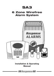
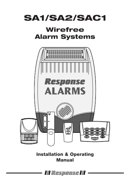
<strong>SA1</strong>/<strong>SA2</strong>/<strong>SAC1</strong><br />
Wirefree<br />
Alarm Systems<br />
1<br />
4<br />
7<br />
0<br />
2 3<br />
5 6<br />
8 9<br />
ON AIR 2<br />
1<br />
LOW BATT.<br />
Installation & Operating<br />
Manual
FOREWORD<br />
The <strong>SA1</strong>, <strong>SA2</strong> and <strong>SAC1</strong> Wirefree Alarm Systems comply<br />
with the requirements of BS6799 Class 1 for Wireless<br />
Alarms. All components are designed and manufactured<br />
to provide a high standard of security protection and long,<br />
reliable service. In addition, the radio devices are tested<br />
and approved by the Radio Regulatory division of the<br />
Department of Trade and Industry (DTI) to ensure that they<br />
will not interfere with other radio equipment. No radio<br />
licence is required, however, the approved radio<br />
frequency is not protected from interference and may be<br />
withdrawn from use at any time subject to the DTI giving<br />
users an appropriate notice period.<br />
These Alarm Systems are designed for ease of<br />
installation using only conventional domestic tools.<br />
However, it is essential that the installer reads and fully<br />
understands the advice and procedures contained in<br />
this manual and plans the system before proceeding<br />
with the installation.<br />
During installation, it is important that the procedures<br />
described in this manual are followed in sequence.<br />
Note: This manual covers the installation and<br />
operation of a number of different kit configurations.<br />
Instructions relating to components not included in<br />
your kit should be ignored.<br />
This manual should be retained in a safe place for<br />
future reference.<br />
IMPORTANT<br />
All components, with the exception of the External<br />
<strong>So</strong>lar Siren are suitable for mounting in dry interior<br />
locations only.<br />
Tools and Equipment Required:<br />
No.0 Philips Screwdriver<br />
No.1 Philips Screwdriver<br />
No.2 Philips Screwdriver<br />
5 & 6mm Masonry Drill Bits<br />
Drill<br />
Bradawl<br />
Small Spirit Level<br />
LOCAL AUTHORITY REGULATIONS<br />
Depending on your location in the country, you may be<br />
required, by law, to notify the Local Authorities and<br />
Police of your new alarm installation.<br />
Local Authority requirements differ from area to area,<br />
therefore, we recommend that you contact your Local<br />
Borough Environmental Officer to obtain full details of<br />
your area's requirements.<br />
SYSTEM SECURITY<br />
This system has been designed to both detect intruders<br />
and act as a strong deterrent to would-be intruders.<br />
Please remember that given adequate knowledge and<br />
time it is possible to overcome any alarm system and we<br />
therefore recommend that an Intruder Alarm is used in<br />
conjunction with good physical protection such as<br />
security window and door locks.<br />
All units in the system are encoded to operate together<br />
using an 8 bit House Code which is configured by the<br />
user/installer to provide the system security code for<br />
your installation. The system House Code can be<br />
changed at any time by the user.<br />
IMPORTANT: All units forming part of your alarm system<br />
must be set to the same House Code.<br />
The system is operated from one or more Remote Control<br />
units and/or Keypads. Care should be taken to ensure that<br />
your Remote Control Unit(s) are not lost or the Keypad<br />
<strong>User</strong> Access code does not become known to other<br />
people as this will compromise the security of your system.<br />
In either event the system house code and/or <strong>User</strong> Access<br />
code should be changed as soon as possible.<br />
In order to detect any attempts to jam the radio channel<br />
used for your alarm system, a special jamming detection<br />
function is incorporated into the <strong>So</strong>lar Siren. If this feature<br />
is enabled, and the radio channel is jammed continuously<br />
for 30 seconds, (when the system is armed), the <strong>So</strong>lar<br />
Siren will emit a series of rapid bleeps for 5 seconds as a<br />
pre-alarm. If the jamming continues for a further 10<br />
seconds or more a full alarm condition will occur.<br />
SAFETY<br />
Always follow the manufacturers advice when using power<br />
tools; steps, ladders etc. and wear suitable protective<br />
equipment (e.g. safety goggles) when drilling holes etc.<br />
Before drilling holes in walls, check for hidden electricity<br />
cables and water pipes, the use of a cable/pipe locater<br />
maybe advisable if in doubt.<br />
When using ladders, ensure that they are positioned on<br />
a firm stable surface at the correct angle and suitably<br />
secured before use.<br />
The use of ear defenders is advisable when working in<br />
close proximity to the Siren due to the high sound level<br />
produced by this device.<br />
<strong>Response</strong><br />
<strong>SA1</strong>/<strong>SA2</strong>/<strong>SAC1</strong> Wirefree Alarm Systems
CONTENTS<br />
Page No.<br />
Page No.<br />
KIT CONTENTS 2<br />
PLANNING AND EXTENDING YOUR WIREFREE<br />
SOLAR ALARM SYSTEM 3<br />
EXTERNAL SOLAR SIREN 4<br />
General Information 4<br />
Positioning the <strong>So</strong>lar Siren 4<br />
Installing the <strong>So</strong>lar Siren 4<br />
Configuring the <strong>So</strong>lar Siren 5<br />
Initial Power-up of the <strong>So</strong>lar Siren 6<br />
OPERATING INSTRUCTIONS 14<br />
System Service Mode 14<br />
System Operating Mode 14<br />
Arming The System 14<br />
Disarming The System 15<br />
Personal Attack (PA) Alarm 16<br />
Battery Monitoring 16<br />
MAINTENANCE 16<br />
ALARM RECORD 17<br />
REMOTE CONTROL UNIT 6<br />
General Information 6<br />
Configuring the Remote Control 6<br />
Testing the Remote Control 7<br />
TROUBLE SHOOTING 18<br />
EXTENDING YOUR ALARM SYSTEM 20<br />
KEYPAD 7<br />
Positioning the Keypad 8<br />
Installing the Keypad 8<br />
Configuring the Keypad 8<br />
Testing the Keypad 9<br />
COMPONENT SPECIFICATION<br />
Back Cover<br />
PASSIVE INFRA RED (PIR)<br />
MOVEMENT DETECTORS 9<br />
Positioning the PIR Movement Detectors 9<br />
Installing the PIR Movement Detectors 10<br />
Configuring the PIR Movement Detectors 11<br />
Testing the PIR Movement Detectors 11<br />
MAGNETIC CONTACT DETECTORS 12<br />
Positioning the Magnetic Contacts 12<br />
Installing the Magnetic Contacts 12<br />
Configuring the Magnetic Contacts 13<br />
Testing the Magnetic Contacts 13<br />
TESTING THE SYSTEM 14<br />
Initial Testing 14<br />
Testing An Installed System 14<br />
<strong>SA1</strong>/<strong>SA2</strong>/<strong>SAC1</strong><br />
1
KIT CONTENTS<br />
The Alarm System should contain the following<br />
components.<br />
Alarm System <strong>SA1</strong> <strong>SA2</strong> <strong>SAC1</strong><br />
External <strong>So</strong>lar Siren Controller 1 1 1<br />
Remote Control 1 1 1<br />
PIR Movement Detectors 2 2 2<br />
Magnetic Contact Set 0 2 2<br />
Keypad 0 1 1<br />
Also included:<br />
Installation & Operating Manual<br />
Fixing pack<br />
Batteries<br />
Sealed lead acid battery<br />
6V/1.2Ahr<br />
(for <strong>So</strong>lar Siren)<br />
9V PP3 Alkaline<br />
battery<br />
(for Keypad and<br />
PIR Detector)<br />
3V CR2032<br />
Lithium Cell<br />
(for Remote<br />
Control<br />
and Magnetic<br />
Contact Sets)<br />
External <strong>So</strong>lar Siren Controller<br />
IMPORTANT<br />
Please check all items are present BEFORE breaking<br />
open the packaging clamshell. No claims for missing<br />
parts will be accepted unless the clamshell is unopened<br />
and intact.<br />
1<br />
4<br />
7<br />
0<br />
2 3<br />
5 6<br />
8 9<br />
ON AIR 2<br />
1<br />
LOW BATT.<br />
EXTENDING THE ALARM SYSTEM<br />
The following additional accessories are available to<br />
enhance your system and provide further protection<br />
and a higher level of security where required.<br />
Keypad<br />
Magnetic<br />
Contact Set<br />
Component:<br />
Two Magnetic Contact Sets<br />
and one Remote Control<br />
Two Passive Infra-Red<br />
Movement Detectors<br />
Two Remote Controls<br />
Product Code<br />
SU1<br />
SU2<br />
SU3<br />
Full details of these accessories are given on page 20.<br />
PIR Movement<br />
Detector<br />
Remote<br />
Control<br />
2 <strong>SA1</strong>/<strong>SA2</strong>/<strong>SAC1</strong>
ON AIR<br />
LOW BATT.<br />
PLANNING AND EXTENDING YOUR WIREFREE<br />
ALARM SYSTEM<br />
The following example below shows typical property<br />
incorporating the suggested positions for the External<br />
Siren, Keypad, PIR and Magnetic Detectors for optimum<br />
security. Use this as a guide for your installation in<br />
conjunction with the recommendations contained in this<br />
manual for planning your intruder alarm system.<br />
1<br />
2<br />
3<br />
4<br />
5 6<br />
7<br />
8<br />
9<br />
0<br />
Before attempting to install your Alarm System it is<br />
important to study your security requirements and plan<br />
your installation.<br />
The alarm system may be extended to provide even<br />
greater protection by fitting additional PlR Movement<br />
Detectors and Magnetic Contact Detectors as required.<br />
<strong>SA1</strong>/<strong>SA2</strong>/<strong>SAC1</strong> 3
EXTERNAL SOLAR SIREN<br />
The Siren and <strong>So</strong>lar Panel are all encapsulated within a<br />
tough polycarbonate housing. This housing provides full<br />
protection against adverse weather conditions. All<br />
electronic components are specially treated to ensure<br />
long, reliable, trouble free operation.<br />
An LED Strobe unit is built into the siren to act as a visible<br />
deterrent/indication that the system is active. The Strobe<br />
LEDs will slowly and alternately flash whether the<br />
system is Armed or Disarmed. During an alarm condition<br />
the Strobe LEDs will flash rapidly.<br />
An integral anti-tamper switch provides additional security<br />
protection to the Siren should any unathorised attempt be<br />
made to interfere with and remove the siren cover.<br />
The Siren is powered by a high capacity 6V/1.2Ahr<br />
rechargeable sealed lead acid battery. A <strong>So</strong>lar Panel<br />
mounted on the top of the housing charges the battery<br />
during daylight hours.<br />
An 9V Alkaline PP3 battery is supplied in the External<br />
Siren to boost the initial power to the unit when the<br />
system is first activated until the <strong>So</strong>lar Panel charges the<br />
main battery.<br />
The Siren unit incorporates the installations Jamming<br />
Detection system which will (if activated) generate an<br />
alarm if any attempt is made to continuously jam the<br />
radio channel used for the system.<br />
POSITIONING THE SOLAR SIREN<br />
The Siren should be located as high as possible in a<br />
prominent position so that it can be easily seen and<br />
heard. The Siren should be mounted on a solid even<br />
surface so that the rear tamper switch is not activated<br />
when mounted. Ensure that the tamper switch does not<br />
fall into the recess between brick courses as this could<br />
prevent the switch from closing.<br />
To provide the optimum amount of daylight to the <strong>So</strong>lar<br />
Panel, you should ideally mount the <strong>So</strong>lar Siren on a<br />
south facing wall. However, an easterly or westerly<br />
position will suffice.<br />
Although the <strong>So</strong>lar Siren is designed to work on any<br />
aspect wall, for optimum performance you should refrain<br />
from siting the unit on a north facing wall, where possible.<br />
Shadows cast by neighbouring walls, trees and roof<br />
overhangs should also be avoided. If the Siren is to be<br />
mounted below the eaves, it should be positioned a<br />
distance of at least twice the width of the eaves<br />
overhang below the eaves. Remember that in winter the<br />
sun is lower in the sky and you should avoid winter<br />
shadows where possible.<br />
The External <strong>So</strong>lar Siren contains a sophisticated radio<br />
receiver. However, reception of radio signals can be<br />
affected by the presence of metallic objects within the<br />
vicinity of the Receiver. It is therefore important to<br />
mount the <strong>So</strong>lar Siren a minimum distance of 1m away<br />
from any external or internal metalwork, (i.e. drainpipes,<br />
gutters, radiators, mirrors etc).<br />
It is recommended that you check the suitability of your<br />
chosen location for the <strong>So</strong>lar Siren by temporarily fitting<br />
it to the external wall. Using the Remote Control, (as<br />
described below) power up the Siren and check that you<br />
can operate the Siren from in and around the property,<br />
and from all locations where you plan to install detectors.<br />
INSTALLING THE SOLAR SIREN<br />
1. Remove the fixing screw from the bottom edge of<br />
the Siren housing and carefully hinge off the front<br />
cover. All electronic components are housed within<br />
the front cover.<br />
2. Hold the mounting plate in position and mark the<br />
positions of the four mounting holes. A spirit level<br />
placed on the casing will ensure a perfect level. Drill<br />
four 6mm holes and fit the wall plugs.<br />
3. Fit two 30mm fixing screws in the top holes leaving<br />
approximately 10mm of the screw protruding.<br />
4. Fit the top keyhole slots of the mounting plate over<br />
the screw heads. Remove the mounting plate and<br />
adjust the screws until they form a neat fit with the<br />
mounting plate with minimal movement.<br />
5. <strong>Secure</strong> the mounting plate in position using two<br />
25mm fixing screws in the bottom fixing holes.<br />
4<br />
<strong>SA1</strong>/<strong>SA2</strong>/<strong>SAC1</strong>
CONFIGURING THE SOLAR SIREN<br />
<strong>So</strong>lar Panel<br />
Receiver<br />
Aerial<br />
Tamper<br />
switch<br />
6 Volt 1.2Ahr<br />
rechargeable<br />
battery<br />
Front cover<br />
locating tabs<br />
Dip switch<br />
cover<br />
7.5 Volt DC<br />
charging adaptor<br />
input<br />
Bleep Disable Link<br />
Siren Disable Link<br />
Jamming<br />
Detection Link<br />
9 Volt PP3 initial<br />
power up battery<br />
Main Configuration<br />
Switch (in C.U. Position)<br />
C.U.<br />
SIREN<br />
Printed circuit<br />
board enclosure<br />
Optional Strobe<br />
Upgrade PCB<br />
House Code<br />
dip switches 1-8<br />
Alarm duration<br />
dip switch 9<br />
C.U. SIREN<br />
View of inside<br />
Siren<br />
<strong>So</strong>lar Siren<br />
Ensure that the <strong>So</strong>lar Siren main configuration switch<br />
on the LED strobe board is set to "C.U." for use with<br />
this alarm system.<br />
Undo the 3 screws holding the DIP Switch Cover in<br />
place and remove the cover.<br />
HOUSE CODE<br />
Under the cover you will find a series of 9 DIP switches.<br />
BEEP DISABLE<br />
The <strong>So</strong>lar Siren will acknowledge signals from the<br />
Remote Control by beeping. It is possible to disable<br />
the beeps if required by removing the jumper link P2<br />
on the circuit board.<br />
SIREN DISABLE<br />
If for any reason you need to disable the Siren, remove<br />
jumper link P3 on the circuit board. This will prevent<br />
the Siren from sounding during an alarm condition.<br />
However, the Siren will still beep to acknowledge<br />
signals from the Remote Control, (provided the beep<br />
feature is not disabled).<br />
Select and record a random combination of ‘ON’ and<br />
‘OFF’ positions for DIP switches 1- 8. This will be the<br />
system House Code that will enable all devices on<br />
the system to communicate with the <strong>So</strong>lar Siren.<br />
IMPORTANT: The house code for your system should<br />
be changed from the factory default settings.<br />
Note: When the <strong>So</strong>lar Siren is viewed as shown above<br />
(<strong>So</strong>lar panel at top) the DIP switches are ‘upside down’.<br />
ALARM DURATION<br />
This is the length of time that the alarm will sound for,<br />
following activation. The Alarm duration can be set for<br />
either 1 or 3 minutes using DIP switch 9 as follows:<br />
ON = 3 minutes<br />
OFF = 1 minute<br />
If accidentally triggered, the alarm can be stopped at<br />
any time using the Remote Control.<br />
JAMMING DETECTION DISABLE<br />
To enable the Jamming Detect feature fit the jumper<br />
link taped to the cover of the Siren control unit across<br />
link pins P1 on the circuit board.<br />
Note: The Jamming Detection circuit is designed to<br />
permanently scan for jamming signals. However, it is<br />
possible that it may detect other local radio<br />
interference operating legally or illegally on the same<br />
frequency. If it is planned to operate the jamming<br />
detection feature we recommend that the system is<br />
monitored for false jamming alarms for at least 2<br />
weeks prior to leaving the Jamming Detection function<br />
permanently enabled<br />
Once you have completed setting your House Code<br />
and system features, refit the DIP switch cover and<br />
replace the three cover fixing screws. Do not over<br />
tighten the screw as this could damage the thread.<br />
<strong>SA1</strong>/<strong>SA2</strong>/<strong>SAC1</strong> 5
INITIAL POWER-UP OF THE<br />
SOLAR SIREN<br />
1. Connect the 9V PP3 initial power battery to the<br />
battery clip.<br />
Connect the rechargeable battery to the charging<br />
leads. Connect the Red lead to the Red (+ve)<br />
terminal and the Black lead the Black (-ve)<br />
terminal.<br />
Note: Once the batteries have been connected,<br />
the unit will be operational and it is important that<br />
the solar panel receives sufficient light to maintain<br />
the battery charge. The unit should not be<br />
repeatedly set into alarm during installation/<br />
testing, as this will rapidly drain the battery.<br />
2. Press the anti tamper switch, the LEDs will flash<br />
together to indicate that the unit is operational.<br />
3. Hinge the front cover locating tabs over the top<br />
edge of the back plate and carefully push the base<br />
of the siren cover into place. <strong>Secure</strong> the Siren<br />
cover in place by refitting the fixing screw in the<br />
bottom edge of the cover. Do not over tighten the<br />
screw as this could damage the thread.<br />
IMPORTANT: Ensure that the rear tamper switch<br />
is closed when you fit the siren cover to the backplate<br />
(i.e. listen for the switch to click). If the switch<br />
does not close this will prevent the <strong>So</strong>lar Siren from<br />
operating correctly. If necessary, remove the siren<br />
cover again and adjust the screw on the back-plate<br />
tamper plunger to ensure the switch closes when<br />
the Siren is secured in position.<br />
4. If fitted remove the protective film covering the<br />
<strong>So</strong>lar Panel.<br />
5. The fitting of the <strong>So</strong>lar Siren is now complete and<br />
the unit is automatically in Service Mode.<br />
While in Service Mode the <strong>So</strong>lar Siren will not<br />
acknowledge any signals from Detectors,<br />
Personal Attack Buttons, Tamper Switches etc.<br />
Service Mode is controlled from the Remote<br />
Control - refer to page 14 for details.<br />
REMOTE CONTROL UNIT<br />
The Remote Control Unit is used to Arm and Disarm<br />
the system. The Remote Control can arm the system<br />
in either Instant or Delay modes.<br />
Arm/<br />
Instant-Arm<br />
Part-Arm/<br />
Delay-Arm<br />
Disarm<br />
The Remote Control Unit also incorporates a<br />
Personal Attack (PA) switch. Activating the PA<br />
switch on the side of the Remote Control will<br />
immediately initiate a Full Alarm condition whether<br />
the system is Armed or Disarmed. The alarm can be<br />
cancelled by pressing the ‘DISARM’ button on the<br />
Remote Control.<br />
Any number of Remote Control Units can be used<br />
with your system, providing they are all coded with<br />
the system House Code.<br />
The Remote Control is powered by a CR2032 type<br />
Lithium cell which under normal conditions will have<br />
an expected life in excess of 1 year. Under normal<br />
battery conditions the LED on the Remote control will<br />
only illuminate when a button is pressed. However,<br />
under low-battery conditions this LED will continue<br />
to flash after the button has been released. When<br />
this occurs the batteries should be replaced as soon<br />
as possible.<br />
CONFIGURING THE REMOTE<br />
CONTROL<br />
Transmit LED<br />
Slide up<br />
to operate<br />
Personal Attack<br />
1. Remove the rear cover by undoing the small<br />
screw on the rear of the Remote Control.<br />
2. Located above the battery cover is a row of 8 DIP<br />
switches. These switches set the House Code for<br />
the Remote Control and must be set to the same<br />
ON/OFF combination as the House Code DIP<br />
switches in the <strong>So</strong>lar Siren.<br />
3. Ensure that the jumper link located immediately<br />
below the House Code DIP switches is removed<br />
for use with this alarm system.<br />
4. Insert the battery under the clip ensuring that the<br />
+ve terminal faces upwards away from the PCB.<br />
6 <strong>SA1</strong>/<strong>SA2</strong>/<strong>SAC1</strong>
5. Replace the rear cover and fixing screw.<br />
House Code<br />
Dip Switches<br />
Jumper Link<br />
Battery Clip<br />
Battery<br />
TESTING THE REMOTE CONTROL<br />
1. Stand within view of the <strong>So</strong>lar Siren, press and hold<br />
the ‘INSTANT-ARM’ button on the Remote Control<br />
for approximately 10 seconds until the <strong>So</strong>lar Siren<br />
acknowledges the signal by emitting one long Beep<br />
(unless Beep Disable has been set). This operation<br />
takes the <strong>So</strong>lar Siren out of Service mode and into<br />
Operating mode (in a Disarmed state).<br />
Note: The ‘INSTANT-ARM’ button should be<br />
released during or immediately after the long<br />
beep, otherwise the system will switch into an<br />
Armed state.<br />
If the Siren continuously sounds at this point it<br />
is likely that the anti tamper switch on the Siren<br />
has not been closed. Press the ‘DISARM’ button<br />
on the Remote Control to switch OFF the Siren.<br />
Remove the Siren from the mounting plate<br />
and adjust the screw on the tamper knob to<br />
ensure the switch closes when the Siren is<br />
secured in position.<br />
2. Arm the system in Instant mode by pressing the<br />
‘INSTANT-ARM’ button. The Siren will acknowledge<br />
the signal by beeping once.<br />
3. Disarm the system by pressing the ‘DISARM’<br />
button. The Siren will acknowledge the signal by<br />
beeping twice.<br />
4. Arm the system in Delay mode by pressing the<br />
‘DELAY-ARM’ button. The Siren will acknowledge<br />
the signal by beeping once and then again after<br />
the 15s entry/exit delay has expired.<br />
5. Disarm the system by pressing the ‘DISARM’<br />
button. The Siren will acknowledge the signal by<br />
beeping twice.<br />
6. To test the range of the <strong>So</strong>lar Siren and Remote<br />
Control, press the ‘DISARM’ button on the Remote<br />
Control from in and around the property and from<br />
all locations where you plan to install detectors,<br />
check that the Siren acknowledges the signals<br />
from the Remote Control by beeping twice each<br />
time the ‘DISARM’ button is pressed.<br />
7. When you have finished testing the Remote Control,<br />
return the system to Service mode by pressing and<br />
holding the ‘DISARM’ button on the Remote Control<br />
for approximately 10 seconds until the <strong>So</strong>lar Siren<br />
acknowledges the signal by emitting one long Beep<br />
(unless Beep Disable has been set)<br />
IMPORTANT<br />
Ensure that the system is in Service mode before<br />
proceeding with the installation, otherwise a full alarm<br />
condition could occur.<br />
KEYPAD<br />
The Remote Keypad is used to control the <strong>So</strong>lar<br />
Siren and to Arm and Disarm the system by entering<br />
a four digit <strong>User</strong> Access Code. The Keypad can arm<br />
the system in either Instant or Delay modes.<br />
The Keypad incorporates an anti tamper protection<br />
facility. Any attempt to open the casing of the Keypad<br />
will immediately initiate a Full Alarm condition even if<br />
the system is disarmed, (unless the system is in<br />
Service mode). In addition if a sequence of more than<br />
16 incorrect key presses in entered the keypad will be<br />
disabled for the next 15s, (except the tamper<br />
protection function).<br />
The Keypad also incorporates a Personal Attack (PA)<br />
facility which will immediately initiate a Full Alarm<br />
condition when activated.<br />
The Keypad is powered by a PP3 Alkaline battery<br />
which under normal conditions will have an expected<br />
life in excess of 2 years. When the battery level drops<br />
and the "LOW BATT" LED on the front of the Keypad<br />
will flash. When this occurs the batteries should be<br />
replaced as soon as possible.<br />
<strong>SA1</strong>/<strong>SA2</strong>/<strong>SAC1</strong> 7
POSITIONING THE KEYPAD<br />
The Keypad is suitable for mounting in dry interior<br />
locations only.<br />
The Keypad should be located within a protected<br />
area so that an intruder cannot reach the Keypad<br />
without opening a protected door or passing through<br />
1<br />
4<br />
7<br />
2<br />
3<br />
an area protected by a PIR Movement Detector. The<br />
Keypad should be mounted in a position close to the<br />
main entrance door so that the user access code can<br />
be entered and the alarm system shut down within<br />
0<br />
5 6<br />
8 9<br />
ON AIR<br />
LOW BATT.<br />
1<br />
2<br />
Fixing<br />
Screw<br />
Wall Fixing<br />
Plate<br />
the 15s entry time period.<br />
Ensure that the position selected for the Keypad is<br />
Jumper Link<br />
(must be removed)<br />
House Code<br />
DIP Switches<br />
within effective range of the Siren, (refer to "Testing of<br />
Remote Control").<br />
Note: DO NOT fix the Keypad to metalwork or locate<br />
the unit within 1m of metalwork (i.e. radiators, water<br />
pipes, etc) as this could affect the radio range of<br />
the Keypad.<br />
INSTALLING THE KEYPAD<br />
Ensure that the solar siren is in service mode.<br />
1. Undo and remove the fixing screw from the bottom<br />
edge of the Keypad and remove the wall mounting<br />
plate.<br />
2. Using the mounting plate as a template, mark the<br />
positions of the two fixing holes on the wall. A small<br />
spirit level will ensure a perfect level.<br />
3. Fix the mounting plate to the wall using the two<br />
18mm No.4 screws and 25mm wall plugs as<br />
required, (a 5mm hole will be required for the wall<br />
plugs). Do not over-tighten the fixing screws as<br />
this may distort or damage the mounting plate.<br />
4. Undo and remove the four fixing screws in the rear<br />
of the Keypad and remove the rear cover.<br />
5. Connect the PP3 Alkaline battery to the battery clip.<br />
6. Configure the Keypad as described below and<br />
then replace the rear cover and fixing screws.<br />
7. Refit and secure the Keypad onto the wall mounting<br />
plate. Do not over-tighten the fixing screws.<br />
Note: The Keypad is supplied with a default <strong>User</strong><br />
Access Code of: 1 2 3 4. However, for security<br />
reasons, it is recommended that this code is<br />
changed to another four digit number which only<br />
you and other users of the system know.<br />
Anti-Tamper<br />
Switch<br />
CONFIGURING THE KEYPAD<br />
1. Located above the battery clip is a row of 8 DIP<br />
switches 1 - 8. These switches set the House<br />
Code for the Remote Control and must be set<br />
to the same ON/OFF combination as the DIP<br />
switches in the <strong>So</strong>lar Siren.<br />
2. Ensure that the jumper link located in the top left<br />
corner of the PCB (shown in the above diagram)<br />
is removed for use with this alarm system.<br />
CHANGING THE USER ACCESS CODE<br />
When using the Keypad the keys must be pressed<br />
firmly and within five seconds of each other. If you<br />
make a mistake, wait five seconds and recommence<br />
programming from the beginning of the sequence.<br />
To change the <strong>User</strong> Access Code, press the following<br />
keys in sequence:<br />
1. Press<br />
1<br />
2. Enter default (or current) <strong>User</strong> Access code:<br />
1 2 3 4<br />
3. Press - The ’on-air’ LED will flash twice<br />
1<br />
4. Enter new <strong>User</strong> Access code:<br />
? ? ? ?<br />
5. Press 1 - the ‘on-air’ LED will flash three times<br />
to confirm the setting has been accepted. If the light<br />
8 <strong>SA1</strong>/<strong>SA2</strong>/<strong>SAC1</strong>
does not flash, wait five seconds and re-enter the<br />
programming sequence from the beginning.<br />
TESTING THE KEYPAD<br />
1. Put the system into Operating mode by pressing<br />
and holding the ‘INSTANT-ARM’ button on the<br />
Remote Control for approximately 10 seconds<br />
until the Siren acknowledges the signal by<br />
emitting one long Beep (unless Beep Disable has<br />
been set).<br />
2. Arm the system in Instant mode by entering the<br />
<strong>User</strong> Access code followed by the ‘INSTANT-<br />
ARM’ button on the Keypad.<br />
? ? ? ? ,<br />
The Siren will acknowledge the signal by beeping<br />
once.<br />
3. Disarm the system entering the <strong>User</strong> Access code<br />
followed by the ‘DISARM’ button on the Keypad.<br />
? ? ? ? , or<br />
The Siren will acknowledge the signal by beeping<br />
twice.<br />
4. Arm the system in Delay mode by entering the<br />
<strong>User</strong> Access code followed by the either ‘DELAY-<br />
ARM’ buttons on the Keypad.<br />
? ? ? ? , 1 or 2<br />
The Siren will acknowledge the signal by beeping<br />
once and then again after the 15s entry delay.<br />
5. Disarm the system entering the <strong>User</strong> Access code<br />
followed by the ‘DISARM’ button on the Keypad.<br />
? ? ? ? ,<br />
The Siren will acknowledge the signal by beeping<br />
twice.<br />
6. Activate the Personal Attack (PA) alarm by<br />
pressing and holding both ‘DELAY-ARM’ buttons<br />
on the Keypad.<br />
and<br />
1 2<br />
After approximately 2 seconds a Full Alarm<br />
condition will be initiated.<br />
7. Immediately Disarm the system entering the <strong>User</strong><br />
Access code followed by the ‘DISARM’ button on<br />
the Keypad.<br />
? ? ? ? ,<br />
The Siren will stop sounding.<br />
8. When you have finished testing the Keypad, return<br />
the system to Service mode by pressing and<br />
holding the ‘DISARM’ button on the Remote<br />
Control for approximately 10 seconds until the<br />
Siren acknowledges the signal by emitting one<br />
long beep (unless Beep Disable has been set).<br />
PASSIVE INFRA RED (PIR)<br />
MOVEMENT DETECTORS<br />
PIR detectors are designed to detect movement in a<br />
protected area by detecting changes in infra-red<br />
radiation levels caused for example when a person<br />
moves within or across the devices field of vision. If<br />
movement is detected an alarm signal will be<br />
generated, (if the system is armed).<br />
Note: PIR detectors will also detect animals, so<br />
ensure that pets are not permitted access to areas<br />
fitted with Passive Infra Red Movement Detectors<br />
when the system is armed.<br />
Any number of PIR Movement Detectors can be used<br />
with your system, providing they are all coded with<br />
the system House Code and are mounted within<br />
effective radio range of the <strong>So</strong>lar Siren.<br />
The PIR Detector is powered by a PP3 Alkaline<br />
battery which under normal conditions will have<br />
an expected life in excess of 1 year. When the<br />
battery level drops, with the PIR in normal<br />
operation mode and the battery cover fitted, the<br />
LED behind the detection window will flash.<br />
When this occurs the batteries should be<br />
replaced as soon as possible.<br />
POSITIONING THE PIR MOVEMENT<br />
DETECTORS<br />
The recommended position for a PIR Movement<br />
Detector is in the corner of a room mounted at a<br />
height between 2 and 2.5m. At this height, the<br />
detector will have a maximum range of up to 12m<br />
with a field of view of 110°.The Position of the PCB<br />
inside the PIR can be set to 5 different positions to<br />
adjust the range and height of the detection pattern<br />
created by the PIR. Setting the PCB in position 3<br />
will reduce the range to approximately 9m, with<br />
position 1 providing a range of approximately 6m.<br />
The recommended position for the PCB is in<br />
position 5. (see diagram overpage).<br />
<strong>SA1</strong>/<strong>SA2</strong>/<strong>SAC1</strong> 9
2m - 2.5m<br />
1 2 3 4 5 6 7 8 9 10<br />
Detector Range (metres)<br />
Note: DO NOT fix the detector to metalwork or<br />
locate the unit within 1m of metalwork (i.e. radiators,<br />
water pipes, etc) as this could affect the radio range<br />
of the Keypad.<br />
INSTALLING THE PIR MOVEMENT<br />
DETECTORS<br />
3m<br />
5m<br />
10m<br />
Ensure that the system is in service mode.<br />
1. Undo and remove the fixing screw from the<br />
bottom edge of the PIR. Carefully pull the<br />
bottom edge of the detector away from the rear<br />
cover and then slide down to release the top<br />
clips.<br />
110°<br />
180°<br />
Detection Zone Pattern for PCB in position 5<br />
When considering and deciding upon the mounting<br />
position for the detector the following points should<br />
be considered to ensure trouble free operation:<br />
2. Carefully drill out the required mounting holes in<br />
the rear cover using 3mm drill according to<br />
whether the unit is being mounted in a corner or<br />
against a flat wall.<br />
Rear Cover<br />
Mounting Hole<br />
Positions<br />
1. Do not position the detector facing a window or<br />
where it is exposed to or facing direct sunlight.<br />
PIR Movement Detectors are not suitable for use<br />
in conservatories.<br />
2. Do not position the detector where it is exposed<br />
to draughts<br />
3. Do not position the detector directly above a<br />
heat source, (e.g. fire, radiator, boiler, etc).<br />
4. Where possible, mount the detector in the<br />
corner of the room so that the logical path of an<br />
intruder would cut across the fan detection<br />
pattern. PIR detectors respond more effectively<br />
to movement across the device than to<br />
movement directly towards it<br />
5. Do not position the detector in a position where<br />
it is subject to excessive vibration<br />
Ensure that the position selected for the PIR<br />
detector is within effective range of the Siren, (refer<br />
to "Testing of Remote Control").<br />
Note: When the system is Armed, household pets<br />
should not be allowed into an area protected by a<br />
PIR Detector as their movement could trigger the<br />
PIR and initiate an alarm.<br />
Fixing<br />
Screw<br />
3. Hold the rear cover in position against the wall<br />
and mark the positions of the fixing holes.<br />
4. Fix the rear cover to the wall using the two<br />
18mm No.4 screws and 25mm wall plugs, (a<br />
5mm hole will be required for the wall plugs). Do<br />
not over-tighten the fixing screws as this may<br />
distort or damage the cover.<br />
5. Configure the PIR detector as described below.<br />
Remember that on initial installation the device<br />
needs to be tested and should therefore be<br />
configured in Walk Test Mode.<br />
6. Check that the detector PCB is located and set<br />
in the correct position to provide the required<br />
detection range.<br />
10<br />
<strong>SA1</strong>/<strong>SA2</strong>/<strong>SAC1</strong>
1 2 3 4 5 6 7 8<br />
1 2 3 4 5<br />
ON<br />
ON<br />
To adjust the PCB position simply slide it up and<br />
down ensuring that the location legs are aligned<br />
with the required position number marked on the<br />
board.<br />
7. To refit the PIR detector to the rear cover, offer<br />
the detector up to the wall bracket and locate the<br />
clips in the top edge into the rear cover. Push the<br />
lower edge of the detector into place and refit the<br />
fixing screw in the bottom edge of the PIR to<br />
secure in position. Do not over-tighten the fixing<br />
screws as this may damage the casing.<br />
CONFIGURING THE PIR MOVEMENT<br />
DETECTORS<br />
Located on the PCB of the PIR Detector are two<br />
blocks of DIP switches (labelled SW2 and SW3).<br />
4. The PIR Detector incorporates an anti-false<br />
alarm feature designed to compensate for<br />
situations where the detector may be affected<br />
by environmental changes, (e.g. insects, air<br />
temperature, etc). This feature is called "Pulse<br />
Count" and may be selected for 1 or 2 pulse<br />
detection.<br />
The recommended setting is for 1 pulse detection.<br />
However, in cases of extreme environmental<br />
problems or if unattributable false alarms are<br />
experienced, it may be necessary to select 2<br />
pulse detection.<br />
To select the required pulse count set DIP switch<br />
5 of SW3 as follows:<br />
ON 1 pulse detection<br />
OFF 2 pulse detection<br />
Note: The higher the Pulse Count the more<br />
movement will be necessary before the PIR<br />
detector will trigger the alarm.<br />
SW3 SW2<br />
1. DIP switches 1 - 8 of SW2 are used to set the<br />
House Code for the PIR Detector and must be set<br />
to the same ON/OFF combination as the House<br />
Code DIP switches in the <strong>So</strong>lar Siren.<br />
2. DIP Switches 1-3 of SW3 must be set as follows<br />
for use with this alarm system:<br />
DIP 1 DIP 2 DIP 3<br />
ON ON OFF<br />
3. DIP switch 4 of SW3 is used to configure the PIR<br />
Detector for walk test mode, which allows the<br />
operation of the detector to be checked during<br />
installation without initiating an alarm.<br />
ON<br />
OFF<br />
5<br />
4<br />
3<br />
2<br />
1<br />
Walk Test mode<br />
Normal operation<br />
Dip Switches<br />
(SW2 and SW3)<br />
PCB Position<br />
Indicator<br />
(positions 1-5)<br />
PCB Board<br />
(slides up and<br />
down to adjust<br />
position)<br />
Note: On initial installation the detector should be<br />
configured into Walk-Test mode ready for testing.<br />
5. Connect the PP3 Alkaline battery to the battery<br />
clip.<br />
Note: When the 9V Alkaline battery is connected<br />
the LED behind the lens will rapidly flash for<br />
approximately 2-3 minutes until the PIR has<br />
warmed-up and stabilised. The LED will then<br />
stop flashing and turn OFF.<br />
TESTING THE PIR MOVEMENT<br />
DETECTORS<br />
Ensure that the system is in service mode.<br />
1. With the PIR detector configured in Walk Test<br />
mode and mounted in position on the wall, allow<br />
2-3 minutes for the detector to stabilise before<br />
commencing the Walk test.<br />
2. Walk into and move slowly around the protected<br />
area, each time the detector senses movement<br />
the LED behind the lens will flash.<br />
Note: In normal operation, with the battery cover<br />
on, the detector LED will not flash on movement<br />
detection.<br />
If necessary re-adjust the detection pattern by<br />
adjusting the mounting position of the PCB within<br />
the PIR housing.<br />
<strong>SA1</strong>/<strong>SA2</strong>/<strong>SAC1</strong> 11
3. Reconfigure the PIR Detector into Normal<br />
operation mode and refit in position.<br />
Note: When the detector is fully installed i.e. battery<br />
cover is refitted; the unit will not detect movement<br />
for approximately 45 seconds after each activation.<br />
(This feature is presant to conserve battery power<br />
and maximise the battery life).<br />
MAGNETIC CONTACT<br />
DETECTOR(S)<br />
The Magnetic Contact Set comprises two parts; a<br />
Detector and a Magnet. They are designed to be fitted<br />
to either doors or windows with the Magnet screwed<br />
to the moving/opening part and the Contact screwed<br />
to the fixed door or window frame.<br />
When the protected door or window is closed the<br />
Detector Contact Switch is held closed by the Magnetic<br />
field from the Magnet. Opening the protected door or<br />
window will remove the magnetic field and allow the<br />
Contact Detector Switch to open generating an alarm<br />
signal, (if the system is armed).<br />
The Magnetic Contact Detector has the facility to<br />
connect an additional wired Magnetic Contact. This<br />
must be of a normally closed contact type with the<br />
contact being opened in order to generate an alarm<br />
condition.<br />
Any number of Magnetic Contact Detectors can be<br />
used with the system, providing they are all coded<br />
with the system House Code and are mounted<br />
within effective radio range of the <strong>So</strong>lar Siren.<br />
Decide which doors and windows are to be protected<br />
by fitting Magnetic Contact Detectors, (usually the<br />
front and back doors as a minimum will have<br />
Magnetic Contact Detectors fitted). However<br />
additional detectors may be fitted where required<br />
to other more vulnerable doors or windows, (e.g.<br />
garage, patio/conservatory doors etc).<br />
Ensure that the position selected for the Magnetic<br />
Contact detector is within effective range of the Siren,<br />
(refer to "Testing of Remote Control").<br />
Note: Take care when fixing the Detector to a metal<br />
frame, or mounting within 1m of metalwork (i.e.<br />
radiators, water pipes, etc) as this could affect the<br />
radio range of the device. If required, it may be<br />
necessary (under exceptional circumstances) to<br />
space the Magnet and Detector away from the metal<br />
surface using a plastic or wooden spacer to achieve<br />
the necessary radio range.<br />
INSTALLING THE MAGNETIC<br />
CONTACTS<br />
Ensure that the system is in service mode.<br />
1. Remove the battery cover by sliding and lifting it<br />
off. (DO NOT use a screw driver to lever off).<br />
2. Remove the battery holder by carefully tilting up<br />
the end and pulling the connector off of the printed<br />
circuit board.<br />
Slide Open and Lift Off<br />
Do Not Use A Screwdriver<br />
The Magnetic Contact Detector is powered by two<br />
CR2032 type Lithium cells which under normal<br />
conditions will have an expected life in excess of<br />
1 year. Under normal battery conditions the LED on<br />
the Detector will not illuminate when the Detector<br />
s triggered, (unless in test mode). However, under<br />
low-battery conditions this LED will be illuminated<br />
for approx 1s when the detector is triggered. When<br />
this occurs the batteries should be replaced as soon<br />
as possible.<br />
Raised Head Screw,<br />
Key-hole Slot Fixing<br />
Double Sided Tape<br />
OR Screw Fixing<br />
Battery<br />
Connector<br />
Small Counter-sunk<br />
Screw Fixing<br />
Tilt and Remove<br />
Battery Holder<br />
and Insert<br />
Two Batteries<br />
POSITIONING THE MAGNETIC<br />
CONTACTS<br />
The Magnetic Contact Detector is suitable for<br />
mounting in dry interior locations only.<br />
3. Mount the Detector to the fixed part of the frame<br />
along the opening edge opposite the hinges<br />
using either the double sided adhesive tape or<br />
screws provided.<br />
12 <strong>SA1</strong>/<strong>SA2</strong>/<strong>SAC1</strong>
When fixing the Detector with screws the top of<br />
the Detector is secured with a keyhole slot over the<br />
head of the smaller pan head screw. The bottom<br />
of the Detector is secured using the 12mm<br />
counter-sunk head screw fitted within the battery<br />
compartment. Carefully drill out the centre of the<br />
fixing screw hole in the battery compartment<br />
using a 3mm drill. Do not over-tighten the fixing<br />
screws as this may distort or damage the casing.<br />
4. Fit the Magnet to the moving part of the door/window<br />
opposite the Detector using the two 15mm fixing<br />
screws. Ensuring that the parallel gap between the<br />
Magnet and Detector is than 10mm and that the<br />
arrow on the Magnet is pointing towards and aligned<br />
with the mark on the top section on the Detector.<br />
(Ensure back<br />
surfaces are flush)<br />
to the same ON/OFF combination as the House<br />
Code DIP switches in the <strong>So</strong>lar Siren.<br />
Anti-Tamper<br />
Switch<br />
Hole for<br />
Mounting<br />
Screw<br />
Terminal Block for Additional<br />
Wired Magnetic Contact<br />
Jumper<br />
Link S2<br />
Location of<br />
Key-hole Screw<br />
(underside)<br />
House Code<br />
Zone<br />
Magnet<br />
Detector<br />
3. DIP Switches 9-11 must be set as follows for use<br />
with this alarm system:<br />
5. If an additional wired Magnetic Contact is required,<br />
this should be wired to the terminal block provided<br />
in the battery compartment. The wired contact<br />
should be connected using two core (24AWG) wire<br />
of maximum length 1.5m.<br />
A cable entry cut-out is provided beside the<br />
terminal block in the battery cover.<br />
6. Configure the Detector as described below.<br />
7. Slide the batteries supplied into the battery holder,<br />
ensuring that the positive (+) side is uppermost on<br />
each battery as it is installed.<br />
8. Carefully refit the battery holder onto the Detector<br />
ensuring that the spring connectors slide onto<br />
either side of the circuit board.<br />
CONFIGURING THE MAGNETIC<br />
CONTACTS<br />
Alternative<br />
Mounting<br />
1. Located in the battery compartment is a row of 11<br />
DIP switches.<br />
2. DIP switches 1-8 are used to set the House Code<br />
for the Magnetic Contact Detector and must be set<br />
DIP 9 DIP 10 DIP 11<br />
ON ON OFF<br />
4. If an additional wired contact is connected to the<br />
Detector, remove the jumper link S2 on the PCB.<br />
IMPORTANT: If an additional wired contact is not<br />
connected then jumper link SW2 must be fitted<br />
for the detector to operate correctly.<br />
TESTING THE MAGNETIC CONTACTS<br />
Ensure that the system is in service mode.<br />
1. Remove the battery cover from the Detector.<br />
The LED on the Detector will illuminate for approx<br />
1s as the battery cover is removed to indicate that<br />
the tamper switch has been activated.<br />
2. Open the door/window to remove the magnet from<br />
the Detector. As the magnet is moved away from the<br />
detector the LED will illuminate for approx 1s to<br />
indicate that the Detector Contact has been triggered<br />
3. If any external Magnetic Contact Sets are<br />
connected to the Detector, operate these one at a<br />
time. Each time a contact is opened the LED on<br />
the Detector should illuminate for 1s to indicate<br />
that it has been triggered.<br />
4. Replace the battery cover on the Detector.<br />
<strong>SA1</strong>/<strong>SA2</strong>/<strong>SAC1</strong> 13
TESTING THE SYSTEM<br />
INITIAL TESTING<br />
As the system is initially installed it is recommended<br />
that each device is tested in turn as it is installed, (refer<br />
to testing instructions for particular device).<br />
TESTING AN INSTALLED SYSTEM<br />
1. Before commencing testing please ensure the<br />
following conditions apply:<br />
- The system is in Operating mode and Disarmed<br />
- There is no movement in any PIR protected area.<br />
- All doors/windows protected by Magnetic Contact<br />
Detectors are closed.<br />
- All battery covers and housings are correctly<br />
fitted.<br />
2. Arm the system by pressing the ‘INSTANT-ARM’<br />
button on the Remote Control. The Siren will<br />
acknowledge the signal by beeping once, (unless<br />
Beep Disable has been selected).<br />
3. After 45 seconds walk into an area protected<br />
by a PIR Movement Detector and ensure that<br />
a Full Alarm condition is initiated, (i.e. the Siren<br />
sounds).<br />
4. Stop the Siren and Disarm the system by pressing<br />
the ‘DISARM’ button on the Remote Control.<br />
5. Continue to test the all PIR Movement Detectors in<br />
turn as described above, (steps 2 - 4). Remember<br />
that the detectors need to settle for at least 40<br />
seconds between each activation.<br />
6. Arm the system by pressing the ‘INSTANT-ARM’<br />
button on the Remote Control.<br />
7. Open a door/window protected by a Magnetic<br />
Contact Detector and ensure that a Full Alarm<br />
condition is initiated.<br />
8. Stop the Siren and Disarm the system by pressing<br />
the ‘DISARM’ button on the Remote Control.<br />
9. Test each Magnetic Contact Detector in turn as<br />
described above, (steps 6 - 8).<br />
10. Arm the system by entering the <strong>User</strong> Access code<br />
followed by the ‘INSTANT-ARM’ button on the<br />
Remote Keypad.<br />
11. Press and hold both ‘DELAY-ARM’ buttons on the<br />
Keypad for approx 2-3 seconds and ensure that a<br />
Full Alarm condition is initiated.<br />
12. Stop the Siren and Disarm the system by entering<br />
the <strong>User</strong> Access code followed by the DISARM<br />
button on the Keypad.<br />
Note: It is recommended that the system is tested<br />
at regular intervals, (every 3 months), to ensure that<br />
all elements of the system are operating correctly.<br />
OPERATING<br />
INSTRUCTIONS<br />
SYSTEM SERVICE MODE<br />
To prevent a Full Alarm condition from being initiated<br />
when either opening the <strong>So</strong>lar Siren or replacing a<br />
battery, it is necessary to first put the system to<br />
Service mode by pressing and holding the ‘DISARM’<br />
button on the remote control for approximately<br />
10 seconds. The Siren will acknowledge the signal<br />
by beeping twice followed by one long beep after 10<br />
seconds, the ‘DISARM’ button can then be released.<br />
When you have completed any alterations to the<br />
system turn the system back to Operating Mode.<br />
SYSTEM OPERATING MODE<br />
To put the system back into Operating Mode press<br />
and hold the ‘INSTANT-ARM’ button on the Remote<br />
Control for approximately 10 seconds until the<br />
Siren acknowledges the signal by emitting one long<br />
beep. The system will be in Operating mode in a<br />
Disarmed state.<br />
Note: The ‘INSTANT-ARM’ button should be released<br />
during or immediately after the long beep, otherwise<br />
the system will switch into an Armed state.<br />
ARMING THE SYSTEM<br />
When leaving the premises, the system must be armed.<br />
However, before doing so, check that all windows are<br />
closed and locked, all protected doors are closed and<br />
PIR Movement Detectors are not obstructed. Ensure<br />
that pets are restricted to areas not protected by PIR<br />
Movement Detectors.<br />
The system has two Armed modes, Instant and Delay.<br />
Instant mode will immediately set the system into a<br />
fully armed state. Any activation of a Detector will<br />
14 <strong>SA1</strong>/<strong>SA2</strong>/<strong>SAC1</strong>
immediately generate a Full Alarm condition. On<br />
returning to and entering the property the system must<br />
be Disarmed before opening any protected door or<br />
entering an area protected by a PIR movement<br />
detector otherwise a Full Alarm condition will occur.<br />
Delay mode will arm the system with a 15 second<br />
entry/exit delay. On arming the system in Delay mode<br />
there will be a 15 second delay before the system<br />
becomes fully active. This allows time for you to leave<br />
the property before the system becomes fully active.<br />
On returning to and entering the property by opening<br />
a protected door or moving through a PIR protected<br />
area the system will be triggered and the Siren will<br />
emit a single long beep. However, a Full Alarm will not<br />
be initiated until the 15 second entry delay has expired<br />
during which time the system should be Disarmed. If<br />
the system is not Disarmed within the entry delay<br />
period a Full Alarm condition will occur.<br />
If a Full Alarm condition is initiated following an<br />
intrusion and a detector being triggered, (while the<br />
system is armed), the Siren will sound continuously<br />
until the pre-set alarm duration time (1 or 3 minutes)<br />
expires when the siren will cease. The system will<br />
then immediately automatically reset and re-arm<br />
itself. In the event that a further detector is triggered<br />
the system will once again initiate a Full Alarm<br />
condition. This process can be repeated up to three<br />
times after which time the system will not<br />
automatically reset.<br />
If a Full Alarm condition is initiated accidentally the<br />
alarm can be stopped immediately by pressing the<br />
‘DISARM’ button on the Remote Control.<br />
Arming The System Instant Mode<br />
The system can be armed in Instant mode using either<br />
the Remote Control or the Keypad as follows:<br />
Remote Control:<br />
Press the ‘INSTANT-ARM’ button,<br />
The Siren will acknowledge the signal by beeping<br />
once.<br />
Arming The System In Delay Mode<br />
The system can be armed in Delay mode using either<br />
the Remote Control or the Keypad as follows:<br />
Remote Control:<br />
Press the ‘DELAY-ARM’ button,<br />
The Siren will acknowledge the signal by beeping<br />
once and then again after the 15s entry/exit period has<br />
expired. The system will not be fully armed and active<br />
until after the second beep.<br />
Keypad:<br />
Enter the <strong>User</strong> Access code followed by followed by<br />
either ‘DELAY-ARM’ button.<br />
? ? ? ? , 1 or 2<br />
The Siren will acknowledge the signal by beeping<br />
once and then again after the 15s entry/exit period has<br />
expired. The system will not be fully armed and active<br />
until after the second beep.<br />
DISARMING THE SYSTEM<br />
The system can be Disarmed using either the Remote<br />
Control or the Keypad as follows:<br />
Remote Control:<br />
Press the ‘DISARM’ button,<br />
The Siren will acknowledge the signal by beeping<br />
twice.<br />
Keypad:<br />
Enter the <strong>User</strong> Access code followed by the ‘DISARM’<br />
button<br />
? ? ? ? ,<br />
The Siren will acknowledge the signal by beeping<br />
twice.<br />
IMPORTANT: If, when the system is disarmed, the<br />
siren emits a series of ten rapid beeps, this indicates<br />
that a Full Alarm condition has been triggered whilst<br />
the system was armed was armed. Check the<br />
security of the property before entering.<br />
1<br />
Keypad:<br />
Enter the <strong>User</strong> Access code followed by the<br />
‘INSTANT-ARM’ button<br />
? ? ? ?<br />
,<br />
The Siren will acknowledge the signal by beeping<br />
once.<br />
<strong>SA1</strong>/<strong>SA2</strong>/<strong>SAC1</strong> 15
PERSONAL ATTACK (PA) ALARM<br />
A full alarm condition can be immediately initiated by<br />
the user at any time (whether the system is armed or<br />
disarmed) in the event of threat or danger by activating<br />
the Personal Attack (PA) facility.<br />
To initiate a Personal Attack alarm from the Remote<br />
Control slide the Personal Attack switch upwards.<br />
To initiate a Personal Attack alarm from the Keypad<br />
press and hold both the 1 and 2 buttons<br />
together for 2 seconds.<br />
A Full Alarm condition will be initiated which will<br />
continue for the alarm duration time (1 or 3 minutes)<br />
when the system will automatically reset or disarmed<br />
from the Remote Control or Keypad.<br />
BATTERY MONITORING<br />
All system devices continuously monitor their battery<br />
condition . When a low battery indicator is activated<br />
the device will continue to operate normally for up to<br />
2 weeks (depending upon system use). However, the<br />
battery for that device should be replaced as soon as<br />
possible.<br />
Before replacing the battery in any device turn the<br />
system to Service mode as previously described.<br />
When the batteries have been replaced, the system<br />
should be turned back to Operating Mode.<br />
The low battery indication for each system component<br />
is as follows:<br />
Remote Control<br />
When the Remote Control is operated under lowbattery<br />
conditions the transmit LED will continue to<br />
flash after the button has been released.<br />
Under normal battery conditions the LED will<br />
extinguish when the button is released.<br />
Keypad<br />
Under low-battery conditions the ‘low-batt’ LED on<br />
the keypad will be illuminated<br />
Note: The Keypad will retain the <strong>User</strong> Access code<br />
setting for approximately 15 seconds whilst the<br />
battery is removed and replaced. If the battery is left<br />
disconnected for a longer period, or has been allowed<br />
to run completely flat the <strong>User</strong> Access code will revert<br />
to the factory default code of 1 2 3 4 when the new<br />
battery is connected. The <strong>User</strong> Access code will then<br />
need reprogramming as detailed on page 8.<br />
PIR Movement Detectors<br />
If the voltage level of any PIR battery falls below 7.5<br />
Volts, the LED behind the detector lens will flash when<br />
movement is detected to indicate that the battery<br />
needs to be replaced.<br />
Under normal battery conditions the LED does not<br />
illuminate unless the PIR detector is in Walk Test<br />
mode.<br />
Magnetic Contact Detectors<br />
When the Detector is activated, under low-battery<br />
conditions the transmit LED will be illuminated<br />
for approximately 1 second as the door/window is<br />
opened.<br />
Under normal battery conditions the LED not<br />
illuminate as the Detector is operated, (unless the<br />
Detector is in Test Mode with the battery cover<br />
removed).<br />
MAINTENANCE<br />
Your Alarm System requires very little maintenance.<br />
However, a few simple tasks will ensure its continued<br />
reliability and operation.<br />
IMPORTANT: Should you, for any reason, have to<br />
completely power-down the system (e.g. to move the<br />
system to a new premises) first put the system into<br />
Service mode before removing the <strong>So</strong>lar Siren cover<br />
and disconnecting the main rechargeable and initial<br />
power-up batteries. Ensure that the solar panel is<br />
covered with a light proof material to prevent it being<br />
energised.<br />
SOLAR SIREN<br />
1. It is recommended that the <strong>So</strong>lar Panel on the top of<br />
the siren housing should be cleaned at least twice a<br />
year, preferably in the Spring and Autumn, using a<br />
soft damp cloth. Do not use abrasive, solvent<br />
based or aerosol cleaners. Do not attempt to clean<br />
inside the unit or allow water to enter the unit.<br />
This will ensure that the <strong>So</strong>lar Panel does not<br />
become affected by the build up of excessive dirt<br />
and receives all the available light.<br />
2. The <strong>So</strong>lar Siren should not be left for long periods<br />
with the batteries connected, unless the unit is<br />
able to receive sufficient light to maintain the<br />
16 <strong>SA1</strong>/<strong>SA2</strong>/<strong>SAC1</strong>
attery charge. Failure to maintain charge to the<br />
unit will result in the rechargeable battery running<br />
unacceptably low. Should this occur, the unit must<br />
be recharged from a 7.5Vdc/100mA supply (e.g.<br />
from a mains adaptor power supply). When repowering<br />
the <strong>So</strong>lar Siren fit a new 9V PP3 leak<br />
proof Alkaline power-up battery to ensure that the<br />
Unit receives sufficient power until the solar panel<br />
can recharge the main battery.<br />
3. The main rechargeable battery has a typical life of<br />
3-4 years and needs no maintenance during this<br />
period, provided the battery is kept charged. The<br />
battery will be damaged if it is stored in a<br />
discharged state for long periods.<br />
DETECTORS, REMOTE CONTROL<br />
AND KEYPAD<br />
The Detectors require very little maintenance. The<br />
batteries should be replaced once a year or when a<br />
low battery status is indicated.<br />
BATTERIES<br />
Note: Before removing the battery cover on any device<br />
to replace the battery ensure that the system is put into<br />
Test mode to avoid initiating a Full Alarm condition.<br />
The specifications for replacement batteries are as<br />
follows:<br />
Remote Controls:<br />
Magnetic Contact<br />
Detectors:<br />
Keypad:<br />
PIR Movement<br />
Detectors:<br />
1 x 3V CR2032 Lithium Cells<br />
(or equivalent)<br />
2 x 3V CR2032 Lithium Cells<br />
(or equivalent)<br />
1 x 9V PP3 Alkaline<br />
1 x 9V PP3 Alkaline<br />
Note: Where applicable only fit PP3 Alkaline type<br />
batteries. Rechargeable batteries should NOT be fitted.<br />
At the end of their useful life the<br />
batteries should be disposed of via a<br />
suitable Recycling Centre. Do not<br />
dispose of with your normal household<br />
waste. DO NOT BURN.<br />
The Rechargeable Batteries contain Sulphuric Acid -<br />
DO NOT ATTEMPT TO OPEN THE CASING.<br />
ALARM RECORD<br />
You may make a note of your <strong>User</strong> Access Codes and Installer Access Code below.<br />
<strong>User</strong> Access Code<br />
System House Code<br />
Use the above diagram to<br />
record your House Code e.g.<br />
This information is confidential and should be kept in a safe location.<br />
<strong>SA1</strong>/<strong>SA2</strong>/<strong>SAC1</strong> 17
TROUBLE SHOOTING<br />
Symptom / Recommendation<br />
Siren gives full alarm condition when arming.<br />
1. Siren anti-tamper switch activated - adjust tamper<br />
plunger and ensure that switch fully closes when<br />
Siren is mounted. If the wall is excessively uneven,<br />
the siren may need relocated to a more suitable<br />
position.<br />
Siren gives full alarm condition when system<br />
has not been activated by an intruder or<br />
is disarmed.<br />
1. Tamper switch activation - check all detector battery<br />
covers for security and <strong>So</strong>lar Siren for adequate<br />
fixing against external wall.<br />
2. Personal Attack Alarm operated from a Remote<br />
Control or Keypad.<br />
3. Jamming detection circuit operation (see page 5).<br />
Siren not responding to detector.<br />
1. Detector battery low - Replace detector battery.<br />
2. System in Service Mode - Turn to Operating mode<br />
using Remote Control (see ‘System Operating Mode’<br />
page 14).<br />
3. Ensure that the detector ‘House Code’ is the same<br />
as that set on the Siren.<br />
4. Ensure detector is within effective radio range of<br />
<strong>So</strong>lar Siren and equipment is not mounted close to<br />
metal objects.<br />
Siren not responding to Remote Control<br />
or Keypad.<br />
1. Ensure that the ‘House Code’ is the same as that set<br />
on the Siren.<br />
2. System in Service Mode - Turn to Operating mode<br />
using Remote Control (see ‘System Operating Mode’<br />
page 14).<br />
3. Incorrect <strong>User</strong> Access code being entered at Keypad.<br />
4. Remote Control/Keypad battery flat - replace battery.<br />
5. Reset system:<br />
a. Disconnect Siren rechargeable and initial powerup<br />
batteries.<br />
b. Cover <strong>So</strong>lar panel with light proof material and<br />
leave system for 1 minute.<br />
c. Reconnect batteries and then remove <strong>So</strong>lar panel<br />
cover and take out of Service Mode.<br />
6. Siren rechargeable battery discharged:<br />
a. Clean <strong>So</strong>lar Panel.<br />
Symptom / Recommendation<br />
b. Check age of rechargeable battery – replace if at<br />
end of useful life.<br />
c. Fit new initial power-up battery and re-power<br />
up siren.<br />
LED on Remote Control not illuminating,<br />
or is dim when unit is operated.<br />
1. Ensure battery is connected with correct polarity.<br />
2. Ensure battery connections are good.<br />
3. Replace battery with Alkaline type.<br />
Keypad not operating (‘On-Air’ light does not<br />
illuminate).<br />
1. Incorrect Access Code being entered.<br />
2. Battery low - replace battery.<br />
PIR Movement Detector false alarming.<br />
1. Ensure that the detector is not pointing at a source<br />
of heat or a moving object.<br />
2. Ensure that the detector is not mounted above a<br />
radiator or heater.<br />
3. Ensure that the detector is not facing a window or in<br />
direct sunlight.<br />
4. Ensure that the detector is not in a draughty area.<br />
5. Pulse count set too low – reset to two pulse<br />
detection.<br />
PIR Movement Detector not detecting a<br />
person’s movement.<br />
1. Check battery connections are good.<br />
2. Pulse count set too high - reset to one pulse<br />
detection.<br />
3. Check that the detector is correctly set up.<br />
(See setting the PIR Movement Detectors page 7).<br />
4. Ensure DIP switches 1-4 of SW3 are correctly set.<br />
5. Ensure that detector is mounted the correct way up,<br />
(i.e. with detection window at the bottom).<br />
6. Ensure that the detector is mounted at the correct<br />
height, (i.e. 2-2.5m).<br />
7. Allow up to three minutes for detector to stabilise.<br />
PIR Movement Detector LED flashes on<br />
detection of movement, (device in normal<br />
operation mode).<br />
1. Low battery - replace battery.<br />
18 <strong>SA1</strong>/<strong>SA2</strong>/<strong>SAC1</strong>
TROUBLE SHOOTING - continued<br />
Symptom / Recommendation<br />
Magnetic Contact Detector not working.<br />
1. Ensure batteries are connected with correct polarity.<br />
2. Ensure battery connections are good.<br />
3. Ensure ‘House Code’ is the same as <strong>So</strong>lar Siren.<br />
4. Ensure DIP switches 9 and 10 are set correctly.<br />
5. If no external contacts are connected ensure jumper<br />
link fitted.<br />
6. If external contacts are connected:<br />
a. Ensure jumper link removed.<br />
b. Check that all contacts are closed.<br />
c. Check all contacts are wired in series.<br />
Symptom / Recommendation<br />
Magnetic Contact Detector false alarming.<br />
1. Ensure that gap between magnet and detector is<br />
less than 10mm.<br />
2. Tamper switch below battery cover not depressed -<br />
check battery cover is fitted correctly and that fixing<br />
lugs are not broken.<br />
LED on Magnetic Contact Detector<br />
illuminating when door or window is opened.<br />
1. Low battery - replace Batteries.<br />
IF YOU HAVE ANY PROBLEMS<br />
RING THE HELPLINE:<br />
Important<br />
notice<br />
following<br />
alarm<br />
installation:<br />
(Lines open 9.00am<br />
to 5.00pm, Monday<br />
01268 563273to Friday.<br />
In order to comply with the Code of Practice on Noise from Intruder Alarms 1981 you should carry<br />
out the following procedures within 48 hours of Intruder Alarm installation.<br />
1. Notify your local police station in writing that an Intruder Alarm System has been installed, giving<br />
names and contact details of at least two persons who have a Remote Control or know the<br />
<strong>User</strong> Access code for the Keypad.<br />
2. Inform the Local Environmental Health Authority of the installation and which police station has<br />
been informed.<br />
3. Ensure that all users are aware of the operating procedures.<br />
4. Immediately inform your Local Authority and police station if there is a change to the persons<br />
who have Remote Controls.<br />
<strong>SA1</strong>/<strong>SA2</strong>/<strong>SAC1</strong> 19
EXTENDING YOUR ALARM SYSTEM<br />
Your system may be extended to provide additional protection by adding additional PIR Movement Detectors, Magnetic<br />
Contact Sets and Remote Control Units.<br />
ACCESSORIES<br />
SU1 - ACCESSORY SET<br />
Comprises: 2 x Magnetic Contact Sets and 1 x Remote Control Unit.<br />
SU1<br />
SU2 - PIR MOVEMENT DETECTORS (TWIN PACK)<br />
Comprises: 2 x PIR Movement Detectors.<br />
SU2<br />
SU3 - REMOTE CONTROL UNITS (TWIN PACK)<br />
Comprises: 2 x Remote Control Units.<br />
SU3<br />
20 <strong>SA1</strong>/<strong>SA2</strong>/<strong>SAC1</strong>
If you have a problem with your Alarm,<br />
please call the Helpline on:<br />
01268 563273<br />
(Lines open 9.00am to 5.00pm, Monday to Friday).<br />
We can solve most problems quickly over the phone.<br />
GUARANTEE<br />
This product (excluding Alkaline batteries) is guaranteed for one year from<br />
the date of purchase against faulty materials or workmanship. We will<br />
repair or replace any faulty product. No liability can be accepted for any<br />
problems caused by fair wear and tear, buyers negligence, improper<br />
fitting or use, local radio interference, wilful or accidental damage, or any<br />
consequential loss or damage howsoever caused. This guarantee does<br />
not affect your statutory rights and is valid in the UK and Eire only.<br />
If an item develops a fault, the product must be returned to the address<br />
below in adequate packaging with:<br />
1. A copy of your original invoice/receipt.<br />
2. A full description of the fault.<br />
3. All relevant batteries.<br />
NOTE:<br />
If If returning a <strong>So</strong>lar Siren, make sure that the rechargeable battery and<br />
initial power up battery are disconnected and secure and that the unit is<br />
packaged to prevent damage in transit.<br />
For security, Recorded or Registered Post is recommended.<br />
<strong>Response</strong>, Novar Electrical Devices and Systems.<br />
The Arnold Centre, Paycocke Road,<br />
Basildon, Essex. SS14 3EA.<br />
<strong>SA1</strong>/<strong>SA2</strong>/<strong>SAC1</strong> Wirefree Alarm Systems<br />
<strong>Response</strong>
ON AIR<br />
LOW BATT.<br />
COMPONENT SPECIFICATION<br />
Novar Electrical Devices<br />
and Systems are<br />
Quality Assurance Registered<br />
to BS EN ISO9001 1994,<br />
by Asta.<br />
External <strong>So</strong>lar Siren<br />
315<br />
mm<br />
1<br />
4<br />
7<br />
0<br />
2<br />
Keypad<br />
5 6<br />
8 9<br />
110<br />
mm<br />
3<br />
1<br />
2<br />
75mm<br />
30<br />
mm<br />
225<br />
mm<br />
85<br />
mm<br />
● RF operating frequency: 433MHz<br />
● Sealed lead acid battery 6V/1.2Ahr<br />
● <strong>So</strong>lar Panel 7.5V - Charge Rate<br />
typically 60mA<br />
● Operation time in complete darkness<br />
– up to 40 days<br />
● Instant alarm mode<br />
● 15s Entry/Exit Delay alarm mode<br />
● High Power Piezo Siren<br />
● Switchable Alarm Duration: 1 and 3 minutes<br />
● Auto reset on activation<br />
● Siren Disable (selectable)<br />
● Dual front and rear anti-tamper protection<br />
● Jamming Detection<br />
● Audible confirmation (selectable)<br />
● RF operating frequency: 433MHz<br />
● Range: 50m max.<br />
● INSTANT-ARM, DELAY-ARM<br />
and DISARM buttons<br />
● Personal Attack (PA) switch<br />
● Instant alarm mode<br />
● 15s Entry/Exit Delay alarm mode<br />
● Transmission indicator<br />
● Battery life > 1 year<br />
● Low battery indicator<br />
Passive Infra-Red<br />
Movement Detector<br />
95<br />
mm<br />
Remote Control<br />
65<br />
mm<br />
40<br />
mm<br />
RESEARCH &<br />
DEVELOPMENT<br />
Our R & D Department is constantly<br />
developing new products.<br />
We practice a policy of continued<br />
improvement and reserve the right<br />
to change specifications<br />
without prior notice.<br />
If you need help,<br />
just dial the<br />
Helpline for expert<br />
technical support<br />
36<br />
mm<br />
71<br />
mm<br />
13<br />
mm<br />
● RF operating frequency: 433MHz<br />
● Range: 50m max.<br />
● Changeable 4 digit <strong>User</strong> Access code.<br />
● Instant alarm mode<br />
● 15s Entry/Exit Delay alarm mode<br />
● Anti-Tamper protected<br />
● Personal Attack (PA) facility<br />
● Battery Life > 1 year<br />
● Low Battery Indicator<br />
● RF operating frequency: 433MHz<br />
● Range: 75m max.<br />
● Detection range: up to 12m at 110°<br />
and 6m at 180°<br />
● Walk test facility<br />
● One or Two pulse count detection<br />
● Anti-Tamper protected<br />
● Corner or surface mount<br />
● Battery Life > 1 year<br />
● Low Battery Indicator<br />
Magnetic Contact<br />
Detector(s)<br />
12<br />
mm<br />
125<br />
mm<br />
52<br />
mm<br />
10<br />
mm<br />
HELPLINE:<br />
01268 563273<br />
(Lines open 9.00am to 5.00pm,<br />
Monday to Friday).<br />
0359<br />
● RF operating frequency: 433MHz<br />
● Range: 75m max.<br />
● Test Mode<br />
● Anti-Tamper protection<br />
● Facility to add external wired Magnetic<br />
Contacts or Personal Attack buttons<br />
● Battery Life >1 year<br />
● Low Battery Indicator<br />
<strong>Response</strong>, Novar Electrical Devices and Systems.<br />
The Arnold Centre, Paycocke Road, Basildon, Essex. SS14 3EA.<br />
26<br />
mm<br />
15<br />
mm<br />
45170PL Ed.1