Index of Refraction of Fused Quartz Glass for Ultraviolet, Visible, and ...
Index of Refraction of Fused Quartz Glass for Ultraviolet, Visible, and ...
Index of Refraction of Fused Quartz Glass for Ultraviolet, Visible, and ...

You also want an ePaper? Increase the reach of your titles
YUMPU automatically turns print PDFs into web optimized ePapers that Google loves.
- -<br />
JOURNAL OF THE OPTICAL SOCIETY OF AMERICA<br />
VOLUME 44, NUMBER 9 SEPTEMBER, 1954<br />
<strong>Index</strong> <strong>of</strong> <strong>Refraction</strong> <strong>of</strong> <strong>Fused</strong> <strong>Quartz</strong> <strong>Glass</strong> <strong>for</strong> <strong>Ultraviolet</strong>, <strong>Visible</strong>,<br />
<strong>and</strong> Infrared Wavelengths*t<br />
WILLIAM S. RODNEY AND ROBERT J. SPINDLER<br />
Optics Division, National Bureau <strong>of</strong> St<strong>and</strong>ards, Washington, D. C.<br />
(Received June 3, 1954)<br />
The index <strong>of</strong> refraction <strong>of</strong> fused quartz glass was determined <strong>for</strong> 24 wavelengths from 0.34669 to 3.5078<br />
microns, using the minimum deviation method. The whole range is covered with a single instrument. The<br />
variation in index between samples was determined <strong>and</strong> no definite variations in dispersion were observed.<br />
Possible relations between purity <strong>and</strong> index are discussed.<br />
1. INTRODUCTION<br />
THE physical <strong>and</strong> optical properties <strong>of</strong> fused<br />
T quartz glass make its increased use in the optical<br />
industry highly desirable whenever it can be readily<br />
produced in optical quality. In composition it is<br />
definitely reproducible as compared with optical<br />
glasses, it is extremely stable, <strong>and</strong> its coefficient <strong>of</strong><br />
thermal expansion is remarkably low. Its transmission<br />
limits, both in the ultraviolet <strong>and</strong> the infrared, are<br />
nearly the same as <strong>for</strong> the crystalline material <strong>and</strong> in<br />
addition it is free from double refraction.<br />
The refractive index <strong>of</strong> fused quartz glass has been<br />
investigated in the ultraviolet <strong>and</strong> visible regions by<br />
Gif<strong>for</strong>d <strong>and</strong> Shenstone <strong>and</strong> by Trommsdorff. These<br />
data, together with some indices by other observers,<br />
are referenced, compared, <strong>and</strong> analysed by Sosman. 1<br />
For the infrared region some indices <strong>of</strong> fused quartz<br />
have been computed from reflection data but experimentally<br />
determined data seem limited to 3-decimalplace<br />
values. 2 Very little precise <strong>and</strong> self-consistent<br />
in<strong>for</strong>mation has previously been obtained by use <strong>of</strong><br />
identical procedures <strong>for</strong> different wavelength regions<br />
<strong>and</strong> <strong>for</strong> different specimens.<br />
2. SAMPLES<br />
Seven prisms <strong>of</strong> fused quartz glass were used in this<br />
investigation. One was made over twenty years ago<br />
from fused quartz glass produced by the General<br />
Electric Company. Its indices in the visible region <strong>and</strong><br />
its degree <strong>of</strong> homogeneity were carefully investigated'<br />
<strong>and</strong> it is used as a refractive-index st<strong>and</strong>ard <strong>for</strong> the<br />
precise calibration <strong>of</strong> refractometers. A second prism<br />
was made <strong>of</strong> domestic fused quartz glass <strong>of</strong> recent<br />
origin, also produced by the General Electric Company.<br />
Two other prisms A <strong>and</strong> B were made from the product<br />
<strong>of</strong> the Heraeus Company in Germany <strong>and</strong> obtained<br />
by Dr. Stanley S. Ballard who made them available<br />
* The work described in this paper was carried out in part<br />
under the sponsorship <strong>of</strong> the U. S. Air Force.<br />
t The material contained in this paper was orally presented at<br />
the fall meeting <strong>of</strong> the Optical Society <strong>of</strong> America, October 1952.<br />
1 Robert B. Sosman, The Properties <strong>of</strong> Silica (Chemical Catalogue<br />
Company, Inc., New York, 1927).<br />
2 C. Mueller <strong>and</strong> H. Wittenhouse, Z. Physik 85, 559 (1933).<br />
3 L. W. Tilton <strong>and</strong> A. Q. Tool. J. Research Natl. Bur. St<strong>and</strong>ards<br />
3, 619 (1929).<br />
<strong>for</strong> this investigation. A fifth prism was made by<br />
grinding <strong>and</strong> polishing windows on the periphery <strong>of</strong> a<br />
6-inch disk recently manufactured by the Nieder<br />
<strong>Fused</strong> <strong>Quartz</strong> Company, Babson Park, Massachusetts.<br />
Another prism was made by placing windows on the<br />
periphery <strong>of</strong> a cylinder <strong>of</strong> Heraeus fused quartz (sample<br />
C) approximately four inches long <strong>and</strong> two inches in<br />
diameter. The seventh sample was made available by<br />
the Corning <strong>Glass</strong> Works, it is known to have extremely<br />
good ultraviolet transmission characteristics but has a<br />
stronger absorption b<strong>and</strong> around 2.6 microns than the<br />
other samples. All seven specimens were <strong>of</strong> near<br />
optical quality <strong>and</strong> free <strong>of</strong> noticeable striae <strong>and</strong> bubbles,<br />
except the disk which has considerable striae. Even in<br />
this case, however, precise data were obtainable.<br />
3. INSTRUMENTS<br />
The Watts precision spectrometer was used <strong>for</strong> the<br />
visible region <strong>and</strong> the Gaertner precision spectrometer<br />
<strong>for</strong> the ultraviolet <strong>and</strong> infrared. Descriptions <strong>of</strong> these<br />
instruments, with photographs, are given in previous<br />
publications by the authors. 4 ' 5 On both instruments<br />
the minimum-deviation method, with its desirable<br />
features <strong>of</strong> high accuracy <strong>and</strong> simplicity <strong>of</strong> index<br />
computations, was used.<br />
The spectra used in these measurements were the<br />
mercury <strong>and</strong> cadmium emissions <strong>for</strong> wavelengths out to<br />
677<br />
approximately two <strong>and</strong> one-half microns <strong>and</strong> the<br />
absorption b<strong>and</strong>s <strong>of</strong> polystyrene beyond this region to<br />
approximately three <strong>and</strong> one-half microns.<br />
A more detailed discussion <strong>of</strong> the instruments <strong>and</strong><br />
procedure will appear in the Journal <strong>of</strong> Research <strong>of</strong> the<br />
National Bureau <strong>of</strong> St<strong>and</strong>ards.<br />
4. DATA<br />
On the Heraeus prisms A <strong>and</strong> B, index determinations<br />
were made at or very near 240 <strong>and</strong> 31C. The average<br />
temperature <strong>of</strong> the room was controlled within 4h0.2 0 C<br />
<strong>and</strong> was determined frequently by means <strong>of</strong> a thermometer<br />
having its bulb near the prism. Temperature<br />
coefficients were then computed <strong>and</strong> small corrections<br />
4 Wm. S. Rodney <strong>and</strong> R. J. Spindler, J. Research Natl. Bur.<br />
St<strong>and</strong>ards 49, 253 (1952).<br />
6 Wm. S. Rodney <strong>and</strong> R. J. Spindler, J. Opt. Soc. Am. 42, 431<br />
(1952).
678<br />
W. S. RODNEY AND R. J. SPINDLER<br />
Vol. 44<br />
TABLE I. Computed indices <strong>of</strong> refraction <strong>of</strong> fused quartz glass (Heraeus B) <strong>and</strong> residuals (o-c)X 105 <strong>for</strong> temperature <strong>of</strong> 24 0 C.<br />
Wavelength Computed Heraeus Heraeus Heraeus Nieder G.E. G.E. Corning<br />
Source (microns) index Eq. 1 sample A sample B sample C disk sample sample 2 silica glass<br />
A-c B-c C-c N-c Gl-c G2-c S-c<br />
cd 0.34669 1.47757 -1 +22 -5<br />
Hg 0.36117 1.47522 +6 0 +6 +31 +23 -6<br />
do 0.365015 1.47465 +5 -3 +6 +26 +21 -9<br />
do 0.404656 1.46971 +6 -2 +21 +8 +31 +21 -6<br />
do 0.435835 1.46677 +7 0 +23 +6 +33 +21 -5<br />
do 0.546074 1.46014 +7 +1 +24 +8 +34 +22 -4<br />
do 0.578012 1.45887 +5 +25<br />
Cd 0.643847 1.45676 +9 0 +25 +9 +34 +24 -5<br />
Hg 1.01398 1.45030 +9 0 +10 +35 +23 -6<br />
do 1.12866 1.44893 +1<br />
do 1.36728 1.44622 +1<br />
do 1.39506 1.44590 -1<br />
do 1.52952 1.44434 +9 0 +10 +35 +24 -7<br />
do 1.6932 1.44234 +1<br />
do 1.81307 1.44078 +1<br />
do 1.97009 1.43861 +8 -1 +8 +36 +25 -8<br />
do 2.24929 1.43431 +1<br />
do 2.32542 1.43303 +9 -1 +7 +39 +28 -10<br />
Polystyrene<br />
absorption 3.2432 1.41326 -5 -5<br />
do 3.2666 1.41263 0 -5<br />
do 3.3033 1.41164 0 -1<br />
do 3.3293 1.41092 0 -6<br />
do 3.4188 1.40839 -12 +3<br />
do 3.5078 1.40577 -4 -7<br />
were made to adjust to exact temperature <strong>of</strong> 240 <strong>and</strong><br />
31'C. On the other prisms all index determinations<br />
were near 24 0 C only.<br />
The refractive indices <strong>of</strong> the Heraeus B prism <strong>for</strong><br />
24 0 C have been represented by means <strong>of</strong> the dispersion<br />
<strong>for</strong>mula'<br />
0.008777808 84.06224<br />
it2= 2.978645+ _ , (1)<br />
2 -0.010609 96.00000-X 2<br />
0<br />
2,<br />
a<br />
.ZC<br />
.05<br />
.01,<br />
0.2 0.5 1.0 2.0<br />
WAVELENGTH,MICRONS<br />
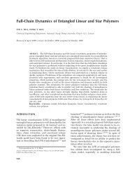
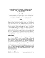
FIG. 1.<br />
THE DISPERSION OF<br />
FUSED QUARTZ GLASS<br />
.02 \ II<br />
GThis is a modification <strong>of</strong> a <strong>for</strong>mula adjusted by Rudolph<br />
Kingslake (private communication)'to fit some <strong>of</strong> our preliminary<br />
<strong>and</strong> the goodness <strong>of</strong> fit <strong>of</strong> the <strong>for</strong>mula is shown by the<br />
small residuals, (B-c), as tabulated in Table I <strong>and</strong><br />
by their nearly r<strong>and</strong>om distribution. The predominance<br />
<strong>of</strong> negative residuals <strong>for</strong> the regions 3 to 3.5g indicates<br />
that further improvement can be made. However no<br />
least squares solution was attempted because at<br />
X=3.4188, where the maximum negative residual was<br />
obtained, there is observational uncertainty because<br />
<strong>of</strong> the very broad nature <strong>of</strong> this absorption b<strong>and</strong> which<br />
tends to make the wavelength <strong>of</strong> the minimum difficult<br />
to determine. Note that a positive residual was obtained<br />
<strong>for</strong> the Corning prism at this wavelength (last column<br />
Table I).<br />
In order to compare the indices <strong>for</strong> the various<br />
prisms, the indices as computed by <strong>for</strong>mula (1) have<br />
been subtracted from all others. These differences are<br />
listed in Table I. It will be noticed that the Heraeus,<br />
Nieder, <strong>and</strong> Corning samples agree in general in<br />
refractivity with the data <strong>of</strong> Trommsdorff <strong>and</strong> <strong>of</strong><br />
Gif<strong>for</strong>d. Gif<strong>for</strong>d's data were taken on the fused quartz<br />
glass made by Gif<strong>for</strong>d <strong>and</strong> Shenstone with particular<br />
attempts at purity <strong>of</strong> material. It seems that the<br />
Heraeus B <strong>and</strong> Corning samples may possibly be the<br />
more free <strong>of</strong> traces <strong>of</strong> other substances, since the<br />
common basic impurities would tend to make the index<br />
higher. The possible effects <strong>of</strong> other impurities cannot<br />
<strong>of</strong> course be altogether ignored. On this assumption<br />
<strong>of</strong> relative purities it seems possible that <strong>for</strong>mula (1)<br />
<strong>and</strong> the first column <strong>of</strong> Table I express probable<br />
data on this prism. It is similar to the <strong>for</strong>mula that Rubens<br />
used <strong>for</strong> the ordinary index <strong>of</strong> quartz [Ann. Phys. 45, 476<br />
(1895)].
September 1954<br />
REFRACTIVE<br />
INDEX OF FUSE QUARTZ GLASS<br />
679<br />
values <strong>for</strong> nearly pure fused quartz glass. Further, it<br />
seems advisable to add 2 or 3X1O-4 <strong>for</strong> probable<br />
values <strong>of</strong> some specimens <strong>of</strong> such glass.<br />
The dispersion <strong>of</strong> fused quartz glass was calculated<br />
over the region measured <strong>and</strong> found to have its minimum<br />
at about 1.5 as shown in Fig. 1. The region<br />
between 2.4 <strong>and</strong> 3.2 is represented as a dashed line<br />
since the strong absorption in this region make measurements<br />
impossible. The region beyond 3.2 has dispersion<br />
good enough to enable one to resolve the polystyrene<br />
b<strong>and</strong>s into six distinct parts.<br />
The temperature coefficients were determined <strong>for</strong><br />
each <strong>of</strong> the lines measured. The precision is not adequate<br />
to determine definitely the variation with wavelength.<br />
The average value at the shorter wavelengths was<br />
found to be 10X 10-6 <strong>and</strong> this may fall to an average <strong>of</strong><br />
about 4.OX 10-6 near 3.5yu. The values in the visible<br />
region agree with those <strong>of</strong> Tilton 3 <strong>and</strong> others.<br />
JOURNAL OF THE OPTICAL SOCIETY OF AMERICA VOLUME 44, NUMBER 9 SEPTEMBER, 1954<br />
Simple Device <strong>for</strong> Reducing Microphotometer Traces to Curves <strong>of</strong> Intensity<br />
J. D. PURCELL<br />
Naval Research Laboratory, Washington 25, D. C.<br />
(Received June 14, 1954)<br />
A mechanical device is described that per<strong>for</strong>ms automatically the laborious task <strong>of</strong> reducing a microphotometer<br />
spectrum trace to a spectral intensity curve. In per<strong>for</strong>ming the conversion the microphotometer<br />
trace, divided into sections, is contact printed onto sensitized material using a narrow slit light source <strong>and</strong><br />
moving the trace <strong>and</strong> photographic material at different rates <strong>of</strong> speed past the slit. The slit is parallel to<br />
the wavelength axis <strong>and</strong>, in effect, scans along the density axis. The photographic material moves at constant<br />
speed, while the motion <strong>of</strong> the trace is controlled by a cam whose shape is essentially the photographic characteristic<br />
curve. The density curve is converted to a curve <strong>of</strong> log intensity in one step, <strong>and</strong> a second step is used<br />
to convert to linear intensity. Other uses <strong>of</strong> the device are suggested.<br />
INTRODUCTION<br />
THE most tedious <strong>and</strong> time consuming operation<br />
in photographic spectrophotometry is the conversion<br />
<strong>of</strong> photographic densities into intensity values<br />
by means <strong>of</strong> the photographic characteristic curve.<br />
This problem is particularly acute where a large number<br />
<strong>of</strong> intensity determinations must be made from a single<br />
film or plate, as in the conversion <strong>of</strong> a microphotometer<br />
tracing <strong>of</strong> a spectrum containing many lines, to a plot<br />
<strong>of</strong> the intensity distribution in the spectrum.<br />
The usual process <strong>of</strong> trans<strong>for</strong>ming microphotometer<br />
tracings into intensity curves begins by tabulating<br />
density values at as many wavelengths as are required<br />
to reproduce the detail in the tracing. The density<br />
values are next converted to intensities by referring<br />
each one to the photographic characteristic curve <strong>for</strong><br />
the particular wavelength region involved. The characteristic<br />
curves, <strong>of</strong> course, have to be determined <strong>for</strong> the<br />
particular emulsion, wavelength range, processing<br />
conditions, <strong>and</strong> so <strong>for</strong>th, which apply to the spectrum<br />
photograph under study. Finally, the completed table<br />
<strong>of</strong> intensity values is plotted against wavelength. This<br />
procedure is quite tedious <strong>and</strong> time consuming in the<br />
case <strong>of</strong> microphotometer tracings <strong>of</strong> very complex<br />
spectra, <strong>and</strong> especially so when it is desirable to preserve<br />
accurately the detail <strong>and</strong> line pr<strong>of</strong>iles. Although<br />
none <strong>of</strong> these steps can be avoided, several instruments<br />
have been developed <strong>for</strong> per<strong>for</strong>ming them more or less<br />
automatically.<br />
Mechanical devices have been described by Beals'<br />
<strong>and</strong> by Weissler, Einarsson, <strong>and</strong> McClell<strong>and</strong>, 2 <strong>for</strong><br />
carrying out the reduction semi-automatically. In<br />
both devices it was necessary <strong>for</strong> the operator continuously<br />
to make a manual adjustment somewhat <strong>of</strong> the<br />
nature <strong>of</strong> curve following. In the case <strong>of</strong> complicated<br />
curves this manual operation would be quite tedious<br />
<strong>and</strong> would have to be carried out at a rather slow speed<br />
to avoid error.<br />
Several microphotometers have been described which<br />
read directly in intensity. The Williams <strong>and</strong> Hiltner<br />
direct intensity microphotometer 3 employs two beams<br />
<strong>of</strong> light which are used to compare the spectrogram<br />
with a specially prepared two-dimensional calibration<br />
spectrogram. Minnaert <strong>and</strong> Houtgast 4 have described<br />
an attachment <strong>for</strong> the Moll microphotometer which<br />
produces a direct-intensity trace. This device requires<br />
an opaque mask whose edge is cut in the <strong>for</strong>m <strong>of</strong> the<br />
photographic characteristic curve. The signal from the<br />
microphotometer photocell is fed into a galvanometer<br />
which sweeps a narrow beam <strong>of</strong> light across this mask.<br />
The light which passes the mask strikes a second photocell<br />
which actuates the recorder. More recently Brown<br />
<strong>and</strong> Birtley' have described an instrument which pro-<br />
'C. S. Beals, J. Roy. Astron. Soc. Can. 38, 65 (1944).<br />
2 Weissler, Einarsson, <strong>and</strong> McClell<strong>and</strong>, Rev. Sci. Instr. 23,<br />
209 (1952).<br />
3 R. C. Williams <strong>and</strong> A. Hiltner, Publ. Am. Astron. Soc. 10, 33<br />
(1939).<br />
4 M. Minnaert <strong>and</strong> J. Houtgast, Z. Astrophys. 15,354 (1938).<br />
5 W. N. Brown <strong>and</strong> W. B. Birtley, Rev. Sci. Instr. 22, 67 (1951).