

SMAJ Transient Voltage Suppressor Diode Series - Extreme-Fire
SMAJ Transient Voltage Suppressor Diode Series - Extreme-Fire
SMAJ Transient Voltage Suppressor Diode Series - Extreme-Fire

Create successful ePaper yourself
Turn your PDF publications into a flip-book with our unique Google optimized e-Paper software.
*RoHS COMPLIANT<br />
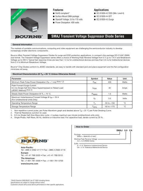
Features<br />
■ RoHS compliant*<br />
■ Surface Mount SMA package<br />
■ Standoff <strong>Voltage</strong>: 5.0 to 170 volts<br />
■ Power Dissipation: 400 watts<br />
Applications<br />
■ IEC 61000-4-2 ESD (Min. Level 4)<br />
■ IEC 61000-4-4 EFT<br />
■ IEC 61000-4-5 Surge<br />
<strong>SMAJ</strong> <strong>Transient</strong> <strong>Voltage</strong> <strong>Suppressor</strong> <strong>Diode</strong> <strong>Series</strong><br />
General Information<br />
The markets of portable communications, computing and video equipment are challenging the semiconductor industry to develop<br />
increasingly smaller electronic components.<br />
Bourns offers <strong>Transient</strong> <strong>Voltage</strong> <strong>Suppressor</strong> <strong>Diode</strong>s for surge and ESD protection applications, in compact chip package DO-214AC (SMA)<br />
size format. The <strong>Transient</strong> <strong>Voltage</strong> <strong>Suppressor</strong> series offers a choice of Working Peak Reverse <strong>Voltage</strong> from 5 V up to 170 V and Breakdown<br />
<strong>Voltage</strong> up to 200 V. Typical fast response times are less than 1.0 ns for unidirectional devices and less than 5.0 ns for bidirectional devices<br />
from 0 V to Minimum Breakdown <strong>Voltage</strong>.<br />
Bourns ® Chip <strong>Diode</strong>s conform to JEDEC standards, are easy to handle with standard pick and place equipment and the flat configuration<br />
minimizes roll away.<br />
Electrical Characteristics (@ T A = 25 °C Unless Otherwise Noted)<br />
Parameter Symbol Value Unit<br />
Minimum Peak Pulse Power Dissipation (T P = 1 ms) (Note 1,2) P PK 400 Watts<br />
Peak Forward Surge Current<br />
8.3 ms Single Half Sine Wave Superimposed on Rated Load<br />
(JEDEC Method) (Note 3) I FSM 40 Amps<br />
Steady State Power Dissipation @ TL = 75 °C P M(AV) 1.0 Watts<br />
Maximum Instantaneous Forward <strong>Voltage</strong> @ I PP = 35 A<br />
(For Unidirectional Units Only)<br />
V F 3.5 Volts<br />
Operating Temperature Range T J -55 to +150 °C<br />
Storage Temperature Range T STG -55 to +175 °C<br />
1. Non-repetitive current pulse, per Pulse Waveform graph and derated above T A = 25 °C per Pulse Derating Curve.<br />
2. Thermal Resistance Junction to Lead.<br />
3. 8.3 ms Single Half-Sine Wave duty cycle = 4 pulses maximum per minute (unidirectional units only).<br />
4. Single Phase, Half Wave, 60 Hz, resistive or inductive load. For capacitive load, derate current by 20 %.<br />
How to Order<br />
<strong>SMAJ</strong> 5.0 CA<br />
Asia-Pacific:<br />
Tel: +886-2 2562-4117 • Fax: +886-2 2562-4116<br />
Europe:<br />
Tel: +41-41 768 5555 • Fax: +41-41 768 5510<br />
The Americas:<br />
Tel: +1-951 781-5500 • Fax: +1-951 781-5700<br />
www.bourns.com<br />
Package<br />
<strong>SMAJ</strong> = SMA/DO-214AC<br />
Working Peak Reverse <strong>Voltage</strong><br />
5.0 = 5.0 VRWM (Volts)<br />
Suffix<br />
A = 5 % Tolerance Unidirectional Device<br />
CA = 5 % Tolerance Bidirectional Device<br />
*RoHS Directive 2002/95/EC Jan 27 2003 including Annex.<br />
Specifi cations are subject to change without notice.<br />
Customers should verify actual device performance in their specifi c applications.
<strong>SMAJ</strong> <strong>Transient</strong> <strong>Voltage</strong> <strong>Suppressor</strong> <strong>Diode</strong> <strong>Series</strong><br />
Electrical Characteristics (@ T A = 25 °C Unless Otherwise Noted)<br />
Unidirectional Device<br />
Bidirectional Device<br />
Breakdown <strong>Voltage</strong><br />
V BR (Volts)<br />
Working<br />
Peak<br />
Reverse<br />
<strong>Voltage</strong><br />
Maximum<br />
Reverse<br />
Leakage<br />
@ V RWM<br />
Maximum<br />
Reverse<br />
<strong>Voltage</strong><br />
@ I RSM<br />
Maximum<br />
Reverse<br />
Surge<br />
Current<br />
Part Part<br />
Part<br />
Part<br />
@ I<br />
Min. Max. T V RWM<br />
Number Marking Number Marking<br />
(mA) (Volts)<br />
I R (μA) V RSM (Volts) I RSM (Amps)<br />
<strong>SMAJ</strong>5.0A HE <strong>SMAJ</strong>5.0CA TE 6.40 7.00 10 5.0 800 / 1600 9.2 43.5<br />
<strong>SMAJ</strong>6.0A HG <strong>SMAJ</strong>6.0CA TG 6.67 7.37 10 6.0 800 / 1600 10.3 38.8<br />
<strong>SMAJ</strong>6.5A HK <strong>SMAJ</strong>6.5CA TK 7.22 7.98 10 6.5 500 / 1000 11.2 35.7<br />
<strong>SMAJ</strong>7.0A HM <strong>SMAJ</strong>7.0CA TM 7.78 8.60 10 7.0 200 / 400 12.0 33.3<br />
<strong>SMAJ</strong>7.5A HP <strong>SMAJ</strong>7.5CA TP 8.33 9.21 1.0 7.5 100 / 200 12.9 31.0<br />
<strong>SMAJ</strong>8.0A HR <strong>SMAJ</strong>8.0CA TR 8.89 9.83 1.0 8.0 50 / 100 13.6 29.4<br />
<strong>SMAJ</strong>8.5A HT <strong>SMAJ</strong>8.5CA TT 9.44 10.4 1.0 8.5 10 / 20 14.4 27.7<br />
<strong>SMAJ</strong>9.0A HV <strong>SMAJ</strong>9.0CA TV 10.0 11.1 1.0 9.0 5 / 10 15.4 26.0<br />
<strong>SMAJ</strong>10A HX <strong>SMAJ</strong>10CA TX 11.1 12.3 1.0 10 5 / 10 17.0 23.5<br />
<strong>SMAJ</strong>11A HZ <strong>SMAJ</strong>11CA TZ 12.2 13.2 1.0 11 5.0 18.2 22.0<br />
<strong>SMAJ</strong>12A IE <strong>SMAJ</strong>12CA UE 13.3 14.7 1.0 12 5.0 19.9 20.1<br />
<strong>SMAJ</strong>13A IG <strong>SMAJ</strong>13CA UG 14.4 15.9 1.0 13 5.0 21.5 18.6<br />
<strong>SMAJ</strong>14A IK <strong>SMAJ</strong>14CA UK 15.6 17.2 1.0 14 5.0 23.2 17.2<br />
<strong>SMAJ</strong>15A IM <strong>SMAJ</strong>15CA UM 16.7 18.5 1.0 15 5.0 24.4 16.4<br />
<strong>SMAJ</strong>16A IP <strong>SMAJ</strong>16CA UP 17.8 19.7 1.0 16 5.0 26.0 15.3<br />
<strong>SMAJ</strong>17A IR <strong>SMAJ</strong>17CA UR 18.9 20.9 1.0 17 5.0 27.6 14.5<br />
<strong>SMAJ</strong>18A IT <strong>SMAJ</strong>18CA UT 20.0 22.1 1.0 18 5.0 29.2 13.7<br />
<strong>SMAJ</strong>20A IV <strong>SMAJ</strong>20CA UV 22.2 24.5 1.0 20 5.0 32.4 12.3<br />
<strong>SMAJ</strong>22A IX <strong>SMAJ</strong>22CA UX 24.4 26.9 1.0 22 5.0 35.5 11.2<br />
<strong>SMAJ</strong>24A IZ <strong>SMAJ</strong>24CA UZ 26.7 29.5 1.0 24 5.0 38.9 10.3<br />
<strong>SMAJ</strong>26A JE <strong>SMAJ</strong>26CA VE 28.9 31.9 1.0 26 5.0 42.1 9.5<br />
<strong>SMAJ</strong>28A JG <strong>SMAJ</strong>28CA VG 31.1 34.4 1.0 28 5.0 45.4 8.8<br />
<strong>SMAJ</strong>30A JK <strong>SMAJ</strong>30CA VK 33.3 36.8 1.0 30 5.0 48.4 8.3<br />
<strong>SMAJ</strong>33A JM <strong>SMAJ</strong>33CA VM 36.7 40.6 1.0 33 5.0 53.3 7.5<br />
<strong>SMAJ</strong>36A JP <strong>SMAJ</strong>36CA VP 40 44.2 1.0 36 5.0 58.1 6.9<br />
<strong>SMAJ</strong>40A JR <strong>SMAJ</strong>40CA VR 44.4 49.1 1.0 40 5.0 64.5 6.2<br />
<strong>SMAJ</strong>43A JT <strong>SMAJ</strong>43CA VT 47.8 52.8 1.0 43 5.0 69.4 5.7<br />
<strong>SMAJ</strong>45A JV <strong>SMAJ</strong>45CA VV 50 55.3 1.0 45 5.0 72.7 5.5<br />
<strong>SMAJ</strong>48A JX <strong>SMAJ</strong>48CA VX 53.3 58.9 1.0 48 5.0 77.4 5.2<br />
<strong>SMAJ</strong>51A JZ <strong>SMAJ</strong>51CA VZ 56.7 62.7 1.0 51 5.0 82.4 4.9<br />
<strong>SMAJ</strong>54A RE <strong>SMAJ</strong>54CA WE 60 66.3 1.0 54 5.0 87.1 4.6<br />
<strong>SMAJ</strong>58A RG <strong>SMAJ</strong>58CA WG 64.4 71.2 1.0 58 5.0 93.6 4.3<br />
<strong>SMAJ</strong>60A RK <strong>SMAJ</strong>60CA WK 66.7 73.7 1.0 60 5.0 96.8 4.1<br />
<strong>SMAJ</strong>64A RM <strong>SMAJ</strong>64CA WM 71.1 78.6 1.0 64 5.0 103 3.9<br />
<strong>SMAJ</strong>70A RP <strong>SMAJ</strong>70CA WP 77.8 86.0 1.0 70 5.0 113 3.5<br />
<strong>SMAJ</strong>75A RR <strong>SMAJ</strong>75CA WR 83.3 92.1 1.0 75 5.0 121 3.3<br />
<strong>SMAJ</strong>78A RT <strong>SMAJ</strong>78CA WT 86.7 95.8 1.0 78 5.0 126 3.2<br />
<strong>SMAJ</strong>85A RV <strong>SMAJ</strong>85CA WV 94.4 104 1.0 85 5.0 137 2.9<br />
<strong>SMAJ</strong>90A RX <strong>SMAJ</strong>90CA WX 100 111 1.0 90 5.0 146 2.7<br />
<strong>SMAJ</strong>100A RZ <strong>SMAJ</strong>100CA WZ 111 123 1.0 100 5.0 162 2.5<br />
<strong>SMAJ</strong>110A SE <strong>SMAJ</strong>110CA XE 122 135 1.0 110 5.0 177 2.3<br />
<strong>SMAJ</strong>120A SG <strong>SMAJ</strong>120CA XG 133 147 1.0 120 5.0 193 2.0<br />
<strong>SMAJ</strong>130A SK <strong>SMAJ</strong>130CA XK 144 159 1.0 130 5.0 209 1.9<br />
<strong>SMAJ</strong>150A SM <strong>SMAJ</strong>150CA XM 167 185 1.0 150 5.0 243 1.6<br />
<strong>SMAJ</strong>160A SP <strong>SMAJ</strong>160CA XP 178 197 1.0 160 5.0 259 1.5<br />
<strong>SMAJ</strong>170A SR <strong>SMAJ</strong>170CA XR 189 209 1.0 170 5.0 275 1.4<br />
Notes:<br />
1. Suffix ‘A’ denotes a 5 % tolerance unidirectional device. 3. For bidirectional devices with a V R of 10 volts or less, the I R limit is double.<br />
2. Suffix ‘CA’ denotes a 5 % tolerance bidirectional device. 4. For unidirectional devices with a V F max. of 3.5 V at an I F of 35 A, 0.5 Sine<br />
Wave of 8.3 ms Pulse Width.<br />
Specifi cations are subject to change without notice.<br />
Customers should verify actual device performance in their specifi c applications.
<strong>SMAJ</strong> <strong>Transient</strong> <strong>Voltage</strong> <strong>Suppressor</strong> <strong>Diode</strong> <strong>Series</strong><br />
Product Dimensions<br />
Recommended Footprint<br />
A<br />
A<br />
B<br />
C<br />
B<br />
C<br />
G<br />
H<br />
Dimension<br />
A<br />
B<br />
C<br />
D<br />
E<br />
F<br />
G<br />
H<br />
F<br />
E<br />
SMA (DO-214AC)<br />
4.06 - 4.57<br />
(0.160 - 0.180)<br />
2.29 - 2.92<br />
(0.090 - 0.115)<br />
1.27 - 1.63<br />
(0.050 - 0.064)<br />
0.15 - 0.31<br />
(0.006 - 0.112)<br />
4.83 - 5.59<br />
(0.190 - 0.220)<br />
0.05 - 0.20<br />
(0.002 - 0.008)<br />
2.01 - 2.62<br />
(0.080 - 0.103)<br />
0.76 - 1.52<br />
(0.030 - 0.060)<br />
D<br />
Dimension<br />
A (Max.)<br />
B (Min.)<br />
C (Min.)<br />
Physical Specifications<br />
DIMENSIONS:<br />
SMA (DO-214AC)<br />
2.70<br />
(0.106)<br />
2.10<br />
(0.083)<br />
1.27<br />
(0.050)<br />
MM<br />
(INCHES)<br />
Case ..........................................Molded plastic per UL Class 94V-0<br />
Polarity ..................... Cathode band indicates unidirectional device<br />
No cathode band indicates bidirectional device<br />
Weight ..................................................0.002 ounces / 0.064 grams<br />
DIMENSIONS:<br />
MM<br />
(INCHES)<br />
Specifi cations are subject to change without notice.<br />
Customers should verify actual device performance in their specifi c applications.
<strong>SMAJ</strong> <strong>Transient</strong> <strong>Voltage</strong> <strong>Suppressor</strong> <strong>Diode</strong> <strong>Series</strong><br />
Rating & Characteristic Curves<br />
Pulse Derating Curve<br />
Maximum Non-Repetitive Surge Current<br />
Peak Pulse Derating in Percent of<br />
Peak Power or Current<br />
100<br />
75<br />
50<br />
25<br />
10 x 1000 Waveform as Defined<br />
by R.E.A.<br />
0<br />
0 25 50 75 100 125 150 175 200<br />
Ambient Temperature ( °C)<br />
Peak Forward Surge Current (Amps)<br />
60<br />
50<br />
40<br />
30<br />
20<br />
Pulse Width 8.3 ms<br />
10 Single Half Sine-Wave<br />
(JEDEC Method)<br />
0<br />
1 2 5 10 20 50 100<br />
Number of Cycles at 60 Hz<br />
Pulse Waveform<br />
Typical Junction Capacitance<br />
I P , Peak Pulse Current (%)<br />
100<br />
50<br />
TR=10 µs<br />
Peak value (IRSM)<br />
Half value= IRSM<br />
2<br />
TA=25 °C<br />
TP<br />
Pulse width (TP)<br />
is defined as that point<br />
where the peak current<br />
decays to 50 % of IPSM.<br />
10 x 1000 waveform<br />
as defined by R.E.A.<br />
Capacitance (pF)<br />
10000<br />
1000<br />
100<br />
Bidirectional<br />
Unidirectional<br />
TA = 25 °C<br />
100<br />
0<br />
0 1.0 2.0 3.0 4.0<br />
T, Time (ms)<br />
Pulse Rating Curve<br />
1.0<br />
0<br />
0 10 100 1000<br />
Standoff <strong>Voltage</strong> (Volts)<br />
Steady State Power Derating Curve<br />
P P , Peak Power (KW)<br />
10<br />
1.0<br />
5.0 mm Lead Areas<br />
TA = 25 °C<br />
Non-repetitive<br />
Pulse Waveform<br />
Shown in Pulse Waveform Graph<br />
0.1<br />
0.1 µs 1.0 µs 10 µs 100 µs 1.0 ms 10 ms<br />
RM(AV) Steady State Power Dissipation (W)<br />
0.8<br />
0.6<br />
0.4<br />
0.2<br />
60 Hz Resistive or<br />
Inductive Load<br />
0.0<br />
0 25 50 75 100 125 150 175 200<br />
TP, Pulse Width<br />
TL, Lead Temperature (°C)<br />
Specifi cations are subject to change without notice.<br />
Customers should verify actual device performance in their specifi c applications.
CDDFN5-0504N <strong>SMAJ</strong> <strong>Transient</strong> - <strong>Voltage</strong> TVS/Steering <strong>Suppressor</strong> <strong>Diode</strong> <strong>Diode</strong> Array<strong>Series</strong><br />
Packaging Information<br />
The product will be dispensed in tape and reel format (see diagram below).<br />
P 0<br />
P 1<br />
d<br />
Index Hole<br />
E<br />
T<br />
120 °<br />
B<br />
F<br />
W<br />
D<br />
1 D<br />
D 2<br />
P<br />
A<br />
C<br />
Trailer Device Leader<br />
End<br />
.......<br />
.......<br />
10 pitches (min.)<br />
.......<br />
.......<br />
....... .......<br />
....... .......<br />
10 pitches (min.)<br />
Start<br />
DIMENSIONS:<br />
MM<br />
(INCHES)<br />
W 1<br />
Direction of Feed<br />
Devices are packed in accordance with EIA standard<br />
RS-481-A and specifications shown here.<br />
Item Symbol SMA (DO-214AC)<br />
Carrier Width<br />
A<br />
2.90 ± 0.10<br />
(0.114 ± 0.004)<br />
Carrier Length<br />
B<br />
5.59 ± 0.10<br />
(0.220 ± 0.004)<br />
Carrier Depth<br />
C<br />
2.36 ± 0.10<br />
(0.093 ± 0.004)<br />
Sprocket Hole<br />
d<br />
1.55 ± 0.05<br />
(0.061 ± 0.002)<br />
Reel Outside Diameter D<br />
330<br />
(12.992)<br />
50.0<br />
Reel Inner Diameter D 1 (1.969) MIN.<br />
13.0 ± 0.20<br />
Feed Hole Diameter D 2 (0.512 ± 0.008)<br />
Sprocket Hole Position E<br />
1.75 ± 0.10<br />
(0.069 ± 0.004)<br />
Punch Hole Position<br />
F<br />
5.50 ± 0.05<br />
(0.217 ± 0.002)<br />
Punch Hole Pitch<br />
P<br />
4.00 ± 0.10<br />
(0.157 ± 0.004)<br />
4.00 ± 0.10<br />
Sprocket Hole Pitch P 0 (0.157 ± 0.004)<br />
2.00 ± 0.05<br />
Embossment Center P 1 (0.079 ± 0.002)<br />
Overall Tape Thickness T<br />
0.30 ± 0.10<br />
(0.012 ± 0.004)<br />
Tape Width<br />
W<br />
12.00 ± 0.20<br />
(0.472 ± 0.008)<br />
18.4<br />
Reel Width W 1 (0.724) MAX.<br />
Quantity per Reel -- 5,000<br />
02/10<br />
Specifi cations are subject to change without notice.<br />
Customers should verify actual device performance in their specifi c applications.


