Probes for Coordinate Measuring Machines - Mitutoyo America ...
Probes for Coordinate Measuring Machines - Mitutoyo America ...
Probes for Coordinate Measuring Machines - Mitutoyo America ...

You also want an ePaper? Increase the reach of your titles
YUMPU automatically turns print PDFs into web optimized ePapers that Google loves.
<strong>Coordinate</strong> <strong>Measuring</strong> <strong>Machines</strong><br />
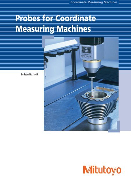
<strong>Probes</strong> <strong>for</strong> <strong>Coordinate</strong><br />
<strong>Measuring</strong> <strong>Machines</strong><br />
Bulletin No. 1989
MPP-300Q/MPP-300<br />
Ultra High-Accuracy Scanning<br />
• Fast scanning<br />
The MPP-300Q/300 is a multi-functional probe designed <strong>for</strong> CNC coordinate measuring<br />
machines. It can not only per<strong>for</strong>m a continuous path contact-type scanning measurement<br />
[a measurement method that implements a collection of a large amount of coordinate<br />
data while traveling along the path in contact with the workpiece] at V2≤0.3µm ( ireference<br />
value when the LEGEX series is installed ), but also high-accuracy point measurement<br />
( σ ≤0.1µm: when the LEGEX series is installed, and data collection from a centering point<br />
measurement (shown below).<br />
• Omni-directional scanning<br />
The MPP-300Q/300 has internally incorporated high-accuracy scales with a minimum<br />
resolution of 0.01µm <strong>for</strong> each direction (X, Y, and Z axes), which makes it possible to read<br />
the stylus displacement in any direction.<br />
The air bearing employed in the sliding section of each axis helps enable this probe with<br />
minimum directionality.<br />
• Low measuring <strong>for</strong>ce<br />
The ordinary touch trigger probe, even if it has only a small <strong>for</strong>ce to generate a trigger<br />
signal the moment the stylus actually comes into contact with the workpiece, may be<br />
subject to several tens to several hundred grams of <strong>for</strong>ce at the press-in that immediately<br />
follows contact. In addition, some of the scanning probes from<br />
other manufacturers employ such a structure that the motor<br />
drive mechanism <strong>for</strong>cibly specifies the probing position in order<br />
to permit the use of a longer stylus, necessitating the probe to<br />
actually have a greater measuring <strong>for</strong>ce.<br />
In contrast, the MPP-300Q/300 can reduce its measuring <strong>for</strong>ce<br />
Centering point<br />
measurement<br />
to a minimum of 0.03N so that it can even measure elastic workpieces<br />
such as resins, etc., without damaging them at all.<br />
•Fast scanning<br />
For a scanning measurement, either of the following scanning methods can be selected:<br />
one in which scanning progresses while automatically following an unknown geometry<br />
(unknown geometry scanning), or one in which scanning progresses based on the locus of<br />
the probe tip given be<strong>for</strong>ehand (known geometry scanning). With known geometry scanning<br />
it is possible to per<strong>for</strong>m fast scanning at 120 mm/s.<br />
Conventionally, it is normal to evaluate geometries such as a line or a circle through point<br />
measurement. However, <strong>for</strong> evaluating the flatness or roundness of an extra precisionmachined<br />
workpiece, it is better to improve the reliability of the measurement result by<br />
evaluating the object at more measurement points.<br />
Un<strong>for</strong>tunately, it takes an extended amount of time <strong>for</strong> a touch-trigger probe to measure<br />
an object point by point. The MPP-300Q/300 can, <strong>for</strong> example, complete its measurement<br />
in several seconds even if it is required to measure inside diameters of ø100 mm at 1000<br />
measurement points. In addition, measurement can be pursued effectively while changing<br />
the scanning speed, depending on the measurement accuracy required.<br />
• Optional units<br />
A wide variety of optional units, including rotary table MRT320 <strong>for</strong> synchronized scanning<br />
and the automatic stylus change system, are provided.<br />
MPP-300Q/MPP-300 Specifications<br />
MPP-300Q/<br />
MPP-300<br />
Automatic<br />
stylus change<br />
system<br />
(optional)<br />
Measurement range<br />
Resolution<br />
Max. permissible probing error<br />
Max. permissible probing error<br />
during scanning<br />
Spring rate<br />
Max. stylus length<br />
Max. stylus mass<br />
Stylus mount<br />
Max. tracing speed<br />
Air flow rate<br />
Probe head<br />
Applicable models<br />
No. of mountable stylus modules<br />
±1mm<br />
0.01µm<br />
MPEP ≤ 0.45mm (LEGEX500/700/900: When the ø4X18mm stylus is used.)<br />
MPETHP ≤1.4mm<br />
(LEGEX500/700/900: When the ø4X18mm stylus is used.)<br />
0.2N/mm<br />
200mm <strong>for</strong> both vertical and horizontal<br />
75g<br />
M4 screw<br />
120mm/s [at a known geometry scanning]<br />
30NL/min<br />
N/A<br />
CNC CMM (LEGEX500/700/900/1200 series)<br />
- 4 standard units [Port 1 is dedicated <strong>for</strong> the standard stylus<br />
(<strong>for</strong> calibration purpose)]<br />
- Expandable to max. 10 ports. Note, all styli should be arranged<br />
on the same axis.<br />
2
MPP-300Q/MPP-300<br />
Ultra High-Accuracy Scanning Probe<br />
Dimensions<br />
96mm<br />
ø14mm<br />
50mmm 32mm 147.5mm<br />
50mm<br />
CLAMP<br />
X<br />
Y<br />
Z<br />
MPP-300<br />
An example scanning measurement of a ring gage with the LEGEX series and MPP-300<br />
ø46mm<br />
ø88mm<br />
Set configuration<br />
Unit Ref. No. Description Part No. Qty Mass (kg) Remark<br />
Configuration<br />
of the MPP-300<br />
main unit No.<br />
02AQD310<br />
MPP-300<br />
probe set<br />
Order No.<br />
06ABJ729<br />
1<br />
2<br />
3<br />
4<br />
5<br />
6<br />
7<br />
8<br />
9<br />
10<br />
11<br />
12<br />
13<br />
14<br />
15<br />
16<br />
MPP-300 probe main unit<br />
Damping oil<br />
Connection air hose<br />
Storage box<br />
ø4X18mm stylus<br />
ø4X50mm stylus<br />
Extension L=30 mm<br />
Extension L=50 mm<br />
Extension L=100 mm<br />
MS4-stylus knuckle<br />
MS4-stylus center<br />
Stylus tool<br />
Allen wrench<br />
Inspection certificate<br />
MPP-300 Hardware Guide<br />
MPP-300 clamp unit configuration (of rack-mount specification)<br />
02AQD330<br />
02AQD090<br />
970117<br />
02AQD480<br />
–<br />
–<br />
181280<br />
181281<br />
06AAD458<br />
06AAD460<br />
06ACH817<br />
181279<br />
538411H<br />
–<br />
99MCA242<br />
02AQD500A<br />
1<br />
1<br />
1<br />
1<br />
1<br />
5<br />
2<br />
1<br />
1<br />
1<br />
1<br />
2<br />
1<br />
1<br />
1<br />
1<br />
1.5<br />
0.017<br />
0.05<br />
1.5<br />
0.002<br />
0.005<br />
0.005<br />
0.007<br />
0.01<br />
0.015<br />
0.04<br />
0.001<br />
0.001<br />
0.002<br />
0.15<br />
Including one stylus mount assembly.<br />
Silicon oil (2000CS)<br />
Air hose <strong>for</strong> MPP-CMM<br />
Wooden box <strong>for</strong> storing MPP-300<br />
Standard stylus<br />
M4-M4 ceramics<br />
M4-M4 ceramics<br />
M4-M4 ceramics<br />
For attaching/detaching M4 stylus<br />
Nominal diameter: 1.5<br />
Hardware-only Operation Manual<br />
Clamp unit 1.8<br />
* Part number may vary with the main unit configuration.<br />
3.3<br />
1<br />
2<br />
CLAMP<br />
X<br />
Y<br />
Z<br />
MPP-300<br />
3<br />
18<br />
5 ø4 ruby ball<br />
6<br />
50<br />
ø4 ruby ball<br />
7<br />
8<br />
9<br />
30<br />
50<br />
100<br />
12 13<br />
Inspection Certificate<br />
14<br />
4<br />
10<br />
Hardware Guide<br />
15<br />
16<br />
11<br />
Stylus mount assembly<br />
Optional units<br />
Automatic Stylus Changer<br />
Dimensions<br />
Measurement range<br />
Unit : mm<br />
Detail<br />
80<br />
60<br />
80<br />
600<br />
60<br />
80<br />
60<br />
80<br />
28<br />
33<br />
115<br />
20<br />
Unit Ref. No. Description Part No. Qty Mass (kg)<br />
1<br />
2<br />
3<br />
4<br />
5<br />
6<br />
Auto-stylus change rack<br />
Stylus mount assembly<br />
Auxiliary plate<br />
ø4X18mm stylus<br />
MS4-stylus center<br />
Reference sphere<br />
06ABG597<br />
02AQD042<br />
06ABG598<br />
—<br />
06ABH817<br />
06ABH818<br />
1<br />
3<br />
1<br />
3<br />
3<br />
1<br />
5<br />
0.04<br />
8<br />
13.04<br />
0.005<br />
0.012<br />
0.04<br />
Automatic stylus<br />
change system<br />
Set Order No.<br />
06ABG596<br />
Remark<br />
Supplied with 4 ports <strong>for</strong> replacement.<br />
Used <strong>for</strong> installing a rack on the CMM base.<br />
For re-calibration<br />
6<br />
Unit : mm<br />
New rack<br />
200<br />
5<br />
1<br />
2<br />
5<br />
20<br />
M4<br />
ø50<br />
ø50<br />
28<br />
110<br />
3<br />
Measurement range<br />
90<br />
720<br />
3
SP80<br />
High-accuracy scanning probe adaptive<br />
to long-type stylus<br />
• High-accuracy scanning probe adaptive to long-type stylus<br />
The SP80 scanning probe is designed to employ a long stylus that has high measurement<br />
accuracy and a maximum length of 500 mm (measured in both the horizontal<br />
and vertical directions). It is a multi-function probe <strong>for</strong> CNC coordinate measuring<br />
machines that undertakes not only scanning measurement (a measurement method<br />
that collects a large amount of coordinate data while traveling along the path in contact<br />
with the workpiece) but also high-accuracy point measurement as well as data<br />
collection from a centering point measurement (shown below).<br />
• Fast scanning<br />
For scanning measurement, either of the following scanning methods can be selected:<br />
one in which scanning progresses while automatically following an unknown geometry<br />
(unknown geometry scanning), or one in which scanning progresses based on the<br />
locus of the probe tip given be<strong>for</strong>ehand (known geometry scanning). With known geometry<br />
scanning it is possible to per<strong>for</strong>m fast scanning at 120 mm/s. Conventionally, it<br />
is normal to evaluate geometries such as a line or circle through point measurement.<br />
However, <strong>for</strong> evaluating the flatness or roundness of an extra precision-machined<br />
workpiece, it is better to improve the reliability of the measurement result by evaluating<br />
the object at more measurement points. Un<strong>for</strong>tunately, extended time is required<br />
<strong>for</strong> a touch-trigger probe to measure an object point by point. The MPP-300Q/300<br />
can, <strong>for</strong> example, complete its measurement in several seconds, even if it is required<br />
to measure inside diameters of ø100 mm at 1000 measurement<br />
points. In addition, any measurement can be pursued<br />
effectively while changing the scanning speed, depending<br />
on the measurement accuracy required.<br />
Centering point<br />
measurement<br />
• Optional units<br />
A wide variety of optional units, including rotary table<br />
MRT320 <strong>for</strong> synchronized scanning and the automatic<br />
stylus change system, are provided.<br />
SP80 Specifications<br />
SP80<br />
Measurement range<br />
Max. permissible probing error<br />
during scanning<br />
Spring rate<br />
Max. stylus length<br />
Max. stylus mass<br />
Stylus mount<br />
Max. scanning speed<br />
Probe head<br />
Applicable models<br />
±2.5mm<br />
MPETHP ≤ 2.0µm (Crysta-Apex C700/900: If the ø8X60mm stylus is used.)<br />
1.8N/mm<br />
500mm<br />
500g<br />
M5<br />
120mm/s [at a known geometry scanning]<br />
N/A<br />
CNC coordinate measuring machines<br />
4
SP80<br />
High-accuracy scanning probe adaptive to long-type stylus<br />
Dimensions<br />
6mm<br />
KM80<br />
150mm<br />
106mm<br />
SH80 main unit<br />
41mm<br />
21mm<br />
SH80<br />
11mm<br />
22mm<br />
5 x M5<br />
Set configuration<br />
SP80 main unit<br />
Description Part No. Mass (kg) Remark<br />
SP80 basic set 06ABT513 2.6 One SP80 main unit, SH80, KM80, and ø8X60mm stylus<br />
Parts <strong>for</strong> SP80<br />
Description Part No.<br />
Mass (kg) Qty<br />
SP80 adapter<br />
SP80 Probe cable<br />
SP80 EXT cable<br />
IU 80<br />
SP80 Power Supply BOX<br />
OPT200S-MPP2<br />
OPT200 attachment<br />
Control ROM (MAIN)<br />
Control ROM (OPT)<br />
06ABT587<br />
06ABT588<br />
06ABT590<br />
06ABT525<br />
06ABT591<br />
06ABN865<br />
06AAS741<br />
06ZAA058<br />
06ZAA059<br />
Mass (kg)<br />
0.3<br />
0.1<br />
0.2<br />
0.51<br />
1<br />
0.2<br />
0.4<br />
0.01<br />
0.01<br />
1<br />
1<br />
1<br />
1<br />
1<br />
1<br />
1<br />
1<br />
1<br />
3.73<br />
* Part number may vary with the main unit configuration.<br />
KM80<br />
SP80 main unit<br />
SH80<br />
Optional units<br />
Automatic Stylus Changer<br />
MRS<br />
SP80 stylus change set 1 (600mm-rail specifications) / Oder No. 06ABT766<br />
Description Part No. Unit Mass (kg)<br />
MRS kit#2<br />
SH80<br />
SCP80<br />
Rack plate (auxiliary plate)<br />
ACR3 attachment<br />
Mass (kg)<br />
06ABT529<br />
06ABT523<br />
06ABT524<br />
06ABG598<br />
06ABP467<br />
1<br />
1<br />
2<br />
1<br />
1<br />
3.5<br />
0.24<br />
2.1<br />
8<br />
0.05<br />
13.89<br />
SCP80<br />
SCP80<br />
34mm<br />
SP80 stylus change set 2 (1000mm-rail specifications) / Oder No. 06ABT767<br />
Description Part No. Unit Mass (kg)<br />
MRS kit#3<br />
SH80<br />
SCP80<br />
Rack plate (auxiliary plate)<br />
ACR3 attachment<br />
Mass (kg)<br />
06ABT530<br />
06ABT523<br />
06ABT524<br />
06ABG598<br />
06ABP467<br />
1<br />
3<br />
4<br />
1<br />
1<br />
3.7<br />
0.48<br />
4.2<br />
8<br />
0.05<br />
16.43<br />
230mm<br />
128mm<br />
5
SP25M<br />
Compact High-accuracy Scanning Probe<br />
Centering point<br />
measurement<br />
• Compact high-accuracy scanning probes<br />
The SP25 is a compact high-accuracy scanning probe with an outside diameter of ø25<br />
mm. This multi-functional probe is suitable <strong>for</strong> a CNC coordinate measuring machine that<br />
per<strong>for</strong>ms not only scanning measurement (measurement method that collects a large<br />
amount of coordinate data while traveling along the path in contact with the workpiece),<br />
but also high-accuracy point measurement, as well as data collection from a centering<br />
point measurement (shown below).<br />
• Fast scanning<br />
For a scanning measurement either of the following scanning methods can be selected:<br />
one in which the scanning progresses while automatically following an unknown geometry<br />
(unknown geometry scanning), and one in which scanning progresses based on the locus<br />
of the probe tip given be<strong>for</strong>ehand (known geometry scanning). With known geometry<br />
scanning it is possible to per<strong>for</strong>m fast scanning at a maximum of 120 mm/s. Conventionally,<br />
it is normal to evaluate geometries such as a line or a circle through point measurement.<br />
However, <strong>for</strong> evaluating the flatness or roundness of an extra precision-machined<br />
workpiece, it is better to improve the reliability of a measurement result by evaluating<br />
the object at more measurement points. Un<strong>for</strong>tunately, an extended of time is required<br />
<strong>for</strong> a touch-trigger probe to measure such an object point by point. The SP-25 can, <strong>for</strong><br />
example, complete its measurement in several seconds even if it is required to measure<br />
inside diameters of ø100 mm at 1000 measurement points. In addition, it can pursue any<br />
measurement effectively while changing the scanning speed, depending on the measurement<br />
accuracy required.<br />
• Enhancing the setup and measurement efficiency through automatic<br />
change of probe orientations<br />
Since the SP25 can be mounted on a probe head such as the PH10M/PH10MQ that<br />
automatically changes the probe orientation, it can greatly reduce the preparation time<br />
<strong>for</strong> measurement and <strong>for</strong> actual measurement in comparison to a conventional-type<br />
scanning probe whose position is fixed downward. In addition, the use of other probes,<br />
as advantaged by the probe change system, makes it possible to realize full automation in<br />
measuring various <strong>for</strong>ms of machined parts.<br />
• Optional units<br />
A wide variety of optional units, including rotary table MRT320 <strong>for</strong> synchronized scanning<br />
and the automatic stylus change system, are provided.<br />
SP25M Specifications<br />
SP25M<br />
Measurement range<br />
Max. permissible probing error<br />
during scanning<br />
Spring rate<br />
Amount of over travel<br />
Max. stylus length<br />
Stylus mount<br />
Max. scanning speed<br />
Probe head<br />
Applicable models<br />
±0.5mm<br />
MPETHP ≤2.3µm<br />
(Crysta-Apex C700/900: If the ø4X50mm stylus is used.)<br />
0.4N/mm<br />
±2.0mm (XY) ±1.7mm (Z)<br />
200mm (When SM25-3 or SH25-3 is used.)<br />
M3<br />
120mm/s [at a known geometry scanning]<br />
Essential: PH10M/PH10MQ<br />
CNC coordinate measuring machines<br />
6
SP25M<br />
Compact High-accuracy Scanning Probe<br />
Dimensions<br />
45.55mm<br />
62.5mm<br />
TM25-20<br />
74.05mm<br />
SM25-1<br />
111.65mm<br />
SM25-2<br />
195.4mm<br />
SM25-3<br />
2mm<br />
ø25mm<br />
SP25M<br />
probe body<br />
TM25-20<br />
ø13.25mm<br />
TP20<br />
module<br />
16.95mm<br />
Stylus that can be attached:<br />
20 to 50mm long<br />
Stylus that can be attached: 26.25mm<br />
20 to 75mm long<br />
(Overall stylus length between 50 to 105mm.)<br />
SH25-1<br />
33.85mm<br />
SH25-2<br />
Stylus that can be attached:<br />
20 to 100mm long<br />
(Overall stylus length between 120 to 200mm.<br />
Fixed to<br />
SH25-3.<br />
48.05mm<br />
SH25-3<br />
ø4mm<br />
Fixed to<br />
SH25-3.<br />
Configuration<br />
Description<br />
SP25M full combination kit<br />
SP25M scanning kit #1<br />
SP25M scanning kit #2<br />
SP25M scanning kit #3<br />
Scanning module SM25-1 kit<br />
Scanning module SM25-2 kit<br />
Scanning module<br />
Stylus holder SH25-1<br />
Stylus holder SH25-2<br />
Stylus holder SH25-3<br />
TM25-20TTP module adapter kit #1<br />
TTP module adapter kit TM25-20<br />
Part No.<br />
06ABS969<br />
06ABS970<br />
06ABS971<br />
06ABS972<br />
06ABS452<br />
06ABS453<br />
06ABS454<br />
06ABS455<br />
06ABS456<br />
06ABS457<br />
06ABS475<br />
06ABS473<br />
Remark<br />
A complete set of SP25M, SM25-1/2/3, SH25-1/2/3,<br />
and TM25-20<br />
A complete set of SP25M, SM25-1, and SH25-1<br />
A complete set of SP25M, SM25-2, and SH25-2<br />
A complete set of SP25M, SM25-3, and SH25-3<br />
A complete set of SM25-1 and SH25-1<br />
A complete set of SM25-2 and SH25-2<br />
A complete set of SM25-3 and SH25-3<br />
A set of TP20 standard <strong>for</strong>ce module and TM25-20<br />
* TTP module (TM25-20, TP20 module) will be supported <strong>for</strong> MCOSMOS V2.4 or later releases.<br />
Optional units<br />
Automatic Scanning Module Changer/Automatic Stylus Changer<br />
* SP25M internally uses the high-power LED light source. Exercise caution when<br />
handing, in accordance with the Operation Manual.<br />
* Can be mounted on the MRS rack.<br />
7
MPP-100<br />
High-Accuracy Scanning Probe<br />
• Low-cost scanning probes<br />
The MPP-100 is a low-price and high-accuracy scanning probe. It is a multi-function probe<br />
<strong>for</strong> CNC coordinate measuring machines that per<strong>for</strong>ms not only a scanning measurement<br />
(a measurement method that collects a large amount of coordinate data while traveling<br />
along the path in contact with the workpiece) but also a high-accuracy point measurement,<br />
as well as data collection from centering point measurement (shown below).<br />
• Fast scanning<br />
For scanning measurement, either of the following scanning methods can be selected:<br />
one in which scanning progresses while automatically following an unknown geometry<br />
(unknown geometry scanning), and one in which scanning progresses based on the locus<br />
of the probe tip given be<strong>for</strong>ehand (known geometry scanning). With known geometry<br />
scanning it is possible to per<strong>for</strong>m fast scanning at 120 mm/s. Conventionally, it is normal<br />
to evaluate geometries such as a line or circle through point measurement. However,<br />
<strong>for</strong> evaluating the flatness or roundness of an extra precision-machined workpiece, it is<br />
better to improve the reliability of a measurement result by evaluating the object at more<br />
measurement points. Un<strong>for</strong>tunately, an extended amount of time is required <strong>for</strong> a touchtrigger<br />
probe to measure such the object point by point. The MPP-100 can, <strong>for</strong> example,<br />
complete its measurement in several seconds, even if it is required to measure inside diameters<br />
of ø100 mm at 1000 measurement points. In addition, it can pursue any measurement<br />
effectively while changing the scanning speed, depending on<br />
the measurement accuracy required.<br />
Centering point<br />
measurement<br />
• Omni-directional scanning<br />
The MPP-100 has internally incorporated high-accuracy scales with<br />
a minimum resolution of 0.01µm <strong>for</strong> each direction (X, Y and Z<br />
axes), which makes it possible to read the stylus displacement in<br />
any direction.<br />
MPP-100 Specifications<br />
MPP-100<br />
Automatic<br />
stylus<br />
change system<br />
(optional)<br />
Measurement range<br />
Resolution<br />
Max. permissible probing error<br />
during scanning<br />
Spring rate<br />
Max. stylus length<br />
Max. stylus mass<br />
Stylus mount<br />
Max. scanning speed<br />
Air flow rate<br />
Probe head<br />
Applicable models<br />
No. of mountable stylus modules<br />
±1mm<br />
0.1µm<br />
MPETHP ≤3.0mm<br />
(Crysta-Apex C series: if the ø4x18mm stylus is used.)<br />
0.75N/mm<br />
200mm <strong>for</strong> both vertical and horizontal<br />
75g<br />
M4 screw<br />
120mm/s<br />
30NL/min<br />
N/A<br />
CNC CMM (Crysta-Apex C series, Bright-STRATO series)<br />
- 4 standard units [Port 1 is dedicated to the standard stylus<br />
(<strong>for</strong> calibration purposes)]<br />
- Expandable to a maximum 10 ports. However, all styli should be<br />
arranged on the same axis.<br />
8
MPP-100<br />
High-Accuracy Scanning Probe<br />
Dimensions<br />
ø90mm<br />
ø14mm<br />
50mm 32mm 141.5mm<br />
50mm<br />
CLAMP<br />
X<br />
Y<br />
Z<br />
MPP-100<br />
ø46mm<br />
ø92mm<br />
Set configuration<br />
Unit Ref. No. Description Part No. Qty Mass (kg) Remark<br />
MPP-100<br />
main unit<br />
configuration<br />
No. 02AQD010<br />
1<br />
2<br />
3<br />
4<br />
5<br />
6<br />
MPP-100 probe main unit<br />
Damping oil<br />
Connection air hose<br />
Storage box<br />
ø4X18mm stylus<br />
ø4X50mm stylus<br />
02AQD030<br />
02AQD090<br />
970117<br />
02AQD020<br />
–<br />
–<br />
1<br />
1<br />
1<br />
1<br />
1<br />
5<br />
1.5<br />
0.017<br />
0.05<br />
1.5<br />
0.002<br />
0.005<br />
7 Extension L=30mm<br />
181280 2 0.005 M4-M4 ceramics<br />
3.3<br />
MPP-100 probe 8 Extension L=50mm<br />
181281 1 0.007 M4-M4 ceramics<br />
set Order No.<br />
06ABG594<br />
Clamp unit<br />
9<br />
10<br />
11<br />
12<br />
13<br />
14<br />
15<br />
16<br />
Extension L=100mm<br />
MS4-stylus knuckle<br />
MS4-stylus center<br />
Stylus tool<br />
Allen wrench<br />
Inspection certificate<br />
MPP-100 Hardware Guide<br />
MPP-100 clamp unit configuration (desktop specification)<br />
06AAD458<br />
06AAD460<br />
06ABH817<br />
181279<br />
538411H<br />
–<br />
99MCA231<br />
02AQD100A<br />
1<br />
1<br />
1<br />
2<br />
1<br />
1<br />
1<br />
1<br />
0.01<br />
0.015<br />
0.04<br />
0.001<br />
0.001<br />
0.002<br />
0.15<br />
1.8<br />
M4-M4 ceramics<br />
Including one stylus mount assembly.<br />
Silicon oil (2000CS)<br />
Air hose <strong>for</strong> MPP-CMM<br />
Wooden box <strong>for</strong> storing MPP-100<br />
Standard stylus<br />
For attaching/detaching M4 stylus<br />
Nominal diameter: 1.5<br />
Hardware-only Operation Manual<br />
* Part numbers may vary with the main unit configuration.<br />
1<br />
2<br />
CLAMP<br />
X<br />
Y<br />
Z<br />
MPP-100<br />
3<br />
18<br />
5 ø4 ruby ball<br />
6<br />
50<br />
ø4 ruby ball<br />
7<br />
8<br />
9<br />
30<br />
50<br />
100<br />
12 13<br />
Inspection Certificate<br />
14<br />
4<br />
10<br />
Hardware Guide<br />
15<br />
16<br />
Stylus mount assembly<br />
11<br />
Unit : mm<br />
Optional units<br />
Automatic stylus change system<br />
Dimensions<br />
Unit : mm<br />
Detail<br />
80<br />
60<br />
80<br />
600<br />
60<br />
80<br />
60<br />
80<br />
Measurement range<br />
33<br />
115<br />
20<br />
28<br />
Unit Ref. No. Description Part No. Qty Mass (kg)<br />
Remark<br />
Automatic<br />
stylus change<br />
system<br />
Set No. 06ABG596<br />
1<br />
2<br />
3<br />
4<br />
5<br />
6<br />
Auto-stylus change rack<br />
Stylus mount assembly<br />
Auxiliary plate<br />
ø4X18mm stylus<br />
MS4-stylus center<br />
Reference sphere<br />
06ABG597<br />
02AQD042<br />
06ABG598<br />
916491<br />
06ABH817<br />
06ABH818<br />
1<br />
3<br />
1<br />
3<br />
3<br />
1<br />
5<br />
0.04<br />
8<br />
13.04<br />
0.005<br />
0.012<br />
0.04<br />
Supplied with 4 ports <strong>for</strong> replacement.<br />
Used <strong>for</strong> installing a rack on the CMM base.<br />
For re-calibration<br />
6<br />
Unit : mm<br />
New rack<br />
1<br />
2<br />
200<br />
5<br />
5<br />
M4<br />
20<br />
Ø50<br />
Ø50<br />
28<br />
110<br />
3<br />
Measurement range<br />
90<br />
720<br />
9
QVP<br />
Quick Vision Probe<br />
• Provides image measuring capability <strong>for</strong> coordinate measuring machines<br />
The QVP probe per<strong>for</strong>ms <strong>for</strong>m measurement by image processing micro geometry that<br />
cannot be measured by a contact type probe, or elastic bodies that are easily de<strong>for</strong>med by<br />
slight measuring <strong>for</strong>ces.<br />
Although the method of microscopic measurement with the centering microscope<br />
mounted on the coordinate measuring machine has been used since coordinate measuring<br />
machines came into use in the industry, they have an inherent disadvantage in that the<br />
operation of identifying positions is dependent on the operator’s eye, resulting in possible<br />
measurement errors. Even with a CNC coordinate measuring machine manual measurement<br />
must be per<strong>for</strong>med sometimes, such as with an installed centering microscope. The<br />
QVP probe is an vision probe dedicated <strong>for</strong> coordinate measuring machines and was developed<br />
based on <strong>Mitutoyo</strong>’s state-of-the-art technology, in order to enable full automation<br />
of image measurement with a CNC coordinate measuring machine. This technology was<br />
originally developed <strong>for</strong> <strong>Mitutoyo</strong> vision measuring machines.<br />
• Automatic detection of workpiece edge<br />
The QVP-captured image will have various automatic edge detections per<strong>for</strong>med by the<br />
dedicated software, Visionpak, and then various calculation processes (calculation of dimensions<br />
and geometrical deviations) will be per<strong>for</strong>med by the general-purpose measurement<br />
program, Geopak.<br />
• Standard provision of white LED illumination<br />
Since the QVP is equipped with the standard co-axial light running through the lens system<br />
as well as white-light LED ring illumination, which is bright and has a long service life, no<br />
auxiliary illumination is required. The light volume can be set to between 0 and 100% at<br />
1% increments.<br />
• Mounting onto the Automatic Probe Changer<br />
The QVP can also be mounted onto an automatic probe changer, allowing full-automatic<br />
measurement including both the contact and non-contact types in combination with the<br />
contact-type probes.<br />
QVP Specifications<br />
QVP main unit<br />
Objective<br />
QVP I/F BOX<br />
CCD size<br />
Optical tube magnification<br />
Illuminating Co-axial<br />
function Ring<br />
Mass<br />
Optical magnification<br />
Observation range (mm)<br />
Working distance (mm)<br />
Magnification<br />
Numerical Aperture (N.A.)<br />
Depth of focus (µm)<br />
Mass<br />
Supply voltage<br />
Frequency<br />
Power capacity<br />
Mass<br />
0.5X<br />
9.6X12.8<br />
59<br />
1X<br />
Optional<br />
0.03<br />
306<br />
70g<br />
1/2 inch (B/W)<br />
0.5X<br />
White light LED source (built-in): Power dissipation 5W or less<br />
White light LED source: Power dissipation 10W or less<br />
Automatic-joint type: 310g, shank type: 385g<br />
1.5X<br />
3.2X4.3<br />
72.3<br />
3X<br />
Standard<br />
0.07<br />
56<br />
47g<br />
AC100 to 240V<br />
50/60Hz<br />
45W<br />
3800g<br />
2.5X<br />
1.9X2.6<br />
59.5<br />
5X<br />
Optional<br />
0.11<br />
23<br />
59g<br />
5X<br />
1X1.3<br />
44<br />
10X<br />
Optional<br />
0.18<br />
8<br />
75g<br />
10
QVP<br />
Quick Vision Probe<br />
Dimensions<br />
Optional accessories<br />
ø70<br />
ø70<br />
66<br />
26 40<br />
Objective ML1X (375-036)<br />
Objective ML5X (375-034)<br />
Objective ML10X (375-035)<br />
50<br />
ø25<br />
66<br />
26 40<br />
ø13.99<br />
113<br />
32<br />
182.7<br />
211.7<br />
Calibration gage<br />
(02AQC310)<br />
- Gage <strong>for</strong> sharing the<br />
coordinates between the QVP<br />
and contact-type probe<br />
W.D.= 72.3<br />
37.7<br />
QVP-A<br />
(Automatic-joint type)<br />
QVP-S<br />
(Shank type)<br />
Calibration chart<br />
(958448)<br />
- Gage <strong>for</strong> calibrating<br />
a single QVP unit<br />
Unit : mm<br />
Data processing unit<br />
Dedicated data processing software VISIONPAK<br />
VISIONPAK operates under the Microsoft Windows operating system<br />
and is a general-purpose measurement program <strong>for</strong> coordinate<br />
measuring machines. It displays the image window when it detects a<br />
workpiece edge. After detecting an edge, it undertakes various<br />
calculations with the regular general-purpose measurement programs.<br />
Wide variety of image processing functions<br />
With the powerful image processing functions (tools) it can detect<br />
various <strong>for</strong>ms of edges at high speed. It can measure in the height<br />
direction by means of its auto-focus function, and save the captured<br />
image as the image data (bitmap <strong>for</strong>mat) as well.<br />
Outlier removal function<br />
In ordinary micro-<strong>for</strong>m measurement it is often difficult to remove burrs<br />
and dusts from the objective workpiece, resulting in an inevitable<br />
measurement error. In contrast, VISIONPAK can recognize, <strong>for</strong> example,<br />
the obstruction as an "outlier" and bypass it during measurement.<br />
VISIONPAK Image Processing Tool<br />
Simple tool<br />
Manual tool<br />
Used <strong>for</strong> detecting a single point<br />
on the edge pointed to by the<br />
arrow.<br />
Box tool<br />
Used <strong>for</strong> detecting an optional<br />
position pointed to (clicked on)<br />
by the mouse.<br />
Centroid tool<br />
Used <strong>for</strong> multiple-point line<br />
measurement of an edge caught<br />
in the box<br />
Circle tool<br />
Used <strong>for</strong> detecting the center of<br />
gravity of an optional <strong>for</strong>m.<br />
Edge self-tracing tool<br />
Used <strong>for</strong> multiple-point measurement<br />
of a circle <strong>for</strong> the objective circular<br />
edge. As with the box tool, it can<br />
collect data that is free from the effect<br />
of burrs and dust.<br />
By simply specifying the start<br />
point and measurement interval,<br />
the objective edge can be<br />
detected while automatically<br />
tracing an unknown geometry.<br />
11
CF20<br />
Centering Microscope <strong>for</strong> <strong>Coordinate</strong><br />
<strong>Measuring</strong> <strong>Machines</strong><br />
• Use the coordinate measuring machine as a large microscope<br />
The CF20 is a centering microscope that enables measurement of small holes and elastic<br />
bodies which are difficult <strong>for</strong> a touch trigger probe to measure. With the CF20 the coordinate<br />
measuring machine can be used as a large microscope.<br />
• Optional accessories to implement various evaluations<br />
To cope with the size and <strong>for</strong>m of a workpiece to be observed and measured, lenses of<br />
various magnifications and reticles <strong>for</strong> <strong>for</strong>m comparison are provided.<br />
• CCTV monitor system<br />
The dedicated CCD camera can be mounted on the back of the CF20 main unit. Video<br />
signals from the camera can be displayed as an image on the external monitor. This is a<br />
great aid in relieving eye stress, especially if several hours of work must be done.<br />
CF20 monocular set dimensions<br />
ø14mm<br />
Eyepiece<br />
Monocular unit<br />
Objective<br />
(optional)<br />
CF20 main unit<br />
211mm<br />
30˚<br />
117mm 50mm<br />
Illumination unit<br />
22.5mm<br />
51mm<br />
CF20 monocular set (375-201) CF20 binocular set (375-202) CF20 protractor eyepiece set CF20 double image set<br />
CF20 disc plate set (375-205)<br />
(375-203)<br />
(375-204)<br />
Shank (ø14mm)<br />
Disc-plate eyepiece unit<br />
Binocular unit<br />
Protractor eyepiece unit<br />
Double-image eyepiece unit<br />
Monocular unit<br />
Shank (ø14mm)<br />
Shank (ø14mm)<br />
Shank (ø14mm)<br />
Shank (ø14mm)<br />
Main unit<br />
Main unit<br />
Main unit<br />
Main unit<br />
Main unit<br />
Specifications<br />
Description<br />
CF20 monocular<br />
set (375-201)<br />
CF20 binocular<br />
set (375-202)<br />
CF20 protractor<br />
eyepiece set<br />
(375-203)<br />
CF20 double<br />
image set<br />
(375-204)<br />
CF20 disc plate<br />
set (375-205)<br />
Specification<br />
Accessory<br />
CF10X eyepiece, field number 22<br />
Cross hair and concentric circle reticle<br />
1. Illumination unit (375-071)<br />
CF10X eyepiece, field number 22<br />
2. Spare lamp (162151)<br />
Cross hair and concentric circle reticle (right)<br />
3. Lens cap<br />
Pupil distance adjustment: 51 - 76mm<br />
CF10X eyepiece, field number 21<br />
4. Tools<br />
Measurement range: 360˚, Angle index: 1˚<br />
5. Power cable<br />
Minimum reading: 5' (vernier scale)<br />
6. Operation Manual<br />
CF10X eyepiece, field number 22<br />
7. Storage box<br />
CF10X eyepiece, field number 22<br />
ISO metric/unify screws<br />
Cross hair and concentric circle reticle/<br />
dotted line cross scale, ML 3X objective<br />
Illumination unit (375-071)<br />
Power<br />
supply box<br />
Lamphouse<br />
12
CF20<br />
Centering Microscope <strong>for</strong> <strong>Coordinate</strong> <strong>Measuring</strong> <strong>Machines</strong><br />
Objectives (optional)<br />
CF 1X CF 2X CF 3X<br />
ML 3X<br />
Unit: mm<br />
5<br />
36.3 73.7<br />
(working distance)<br />
110<br />
(parfocal distance)<br />
0.2<br />
0.2<br />
1<br />
10<br />
1<br />
¯ 30<br />
¯ 26<br />
¯ 25<br />
¯ 30<br />
¯ 22<br />
¯ 25<br />
¯ 30<br />
¯ 25<br />
¯ 30<br />
¯ 25<br />
12<br />
18 92<br />
(working distance)<br />
110<br />
(parfocal distance)<br />
5<br />
32.2 77.8<br />
(working distance)<br />
110<br />
(parfocal distance)<br />
5<br />
37.5 72.5<br />
(working distance)<br />
110<br />
(parfocal distance)<br />
ML 5X<br />
ML 10X<br />
CF zoom 1X - 5X<br />
¯ 30<br />
¯ 17<br />
¯ 25<br />
¯ 28<br />
¯ 30<br />
¯ 21.2<br />
¯ 25<br />
¯ 28<br />
¯ 34<br />
¯ 21.5<br />
¯ 25<br />
¯ 37.2<br />
10.5<br />
50.5 59.5<br />
(working distance)<br />
110<br />
(parfocal distance)<br />
8<br />
66 44<br />
(working distance)<br />
110<br />
(parfocal distance)<br />
11.5<br />
60 50<br />
(working distance)<br />
110<br />
(parfocal distance)<br />
Order No. Description<br />
Numerical Working distance Resolution Depth of focus of single Mass<br />
Aperture (N.A.) W.D. (mm) R (µm) objective lens ±D.F. (µm) (g)<br />
375-031<br />
375-032<br />
375-033<br />
375-037<br />
375-034<br />
375-035<br />
CF 1X<br />
CF 2X<br />
CF 3X<br />
ML 3X<br />
ML 5X<br />
ML 10X<br />
0.03<br />
0.06<br />
0.07<br />
0.07<br />
0.11<br />
0.18<br />
73.7<br />
92<br />
77.8<br />
72.5<br />
59.5<br />
44.0<br />
9.2<br />
4.6<br />
3.9<br />
3.9<br />
2.5<br />
1.5<br />
306<br />
76<br />
56<br />
56<br />
23<br />
8<br />
45<br />
35<br />
35<br />
45<br />
80<br />
100<br />
375-038<br />
1X 0.04<br />
6.9<br />
171<br />
CF zoom<br />
3X 0.1<br />
50<br />
2.75<br />
27<br />
200<br />
1X - 5X<br />
5X 0.1<br />
2.75<br />
27<br />
Values <strong>for</strong> resolution and depth of focus of a single objective lens are calculated based on the reference wavelength ( ∆=0.55µm).<br />
The real field of view (mm) can be obtained from Field number/Objective magnification.<br />
Fiber optic circular illumination unit<br />
(176-366)<br />
Twin-fiber optic illumination unit<br />
(176-344)<br />
Unit: mm<br />
¯18<br />
(cross hair and<br />
concentric circle)<br />
(90 /60 dash-dot line)<br />
No. 375-021 No. 375-022 No. 375-023 No. 375-024<br />
60<br />
10<br />
(grid)<br />
CCTV Monitor System <strong>for</strong> CMM with CF20 [Order No. 320-053]<br />
5. C-mount adapter (C)<br />
1. 1/2-inch, 410,000-pixel<br />
color camera<br />
Monitor cable (supplied with<br />
the color monitor of 3,<br />
below)<br />
4. Camera cable,<br />
length: 3m<br />
6. Operation<br />
Manual<br />
3. Color monitor,<br />
2. Controller<br />
- Vertical reference line: Move, lock<br />
15-inches<br />
(2 <strong>for</strong> each vertical and horizontal line)<br />
- Video output: VGA, NTSC (VBS), Y/C synchronous outputs<br />
CCTV (VGA) system<br />
Ref. No.<br />
1<br />
2<br />
3<br />
4<br />
5<br />
6<br />
Part No.<br />
06AAV876<br />
06AAV875<br />
06AAV877<br />
06AAV878<br />
972031<br />
Description<br />
1/2-inch color camera<br />
Controller<br />
Color monitor unit<br />
Camera cable<br />
C-mount adapter (C)<br />
User's Manual<br />
Qty<br />
1<br />
1<br />
1<br />
1<br />
1<br />
1<br />
CCD<br />
Manufactured by SONY<br />
Length: 3m<br />
Common to 176-372<br />
Remark<br />
Color TV (VGA) System No. 06AAV874,<br />
which includes the accessory set of<br />
Ref. Nos. 1 to 4 (common to the order<br />
No. 176-372 CCD Color TV System)<br />
Real field of view (mm) on the monitor can be obtained from CCD camera's imaging device pixels (VxH)/Objective magnification.<br />
13
TP7M ( high-accuracy )<br />
High-Accuracy Touch Trigger Probe<br />
• High-accuracy touch trigger probes<br />
This is a high-accuracy touch trigger probe with a maximum repeatability of 2σ≤0.25µm.<br />
• Enhancing the setup and measurement efficiency through automatic<br />
change of probe orientations<br />
Since the TP7M can be mounted on a probe head, such as the PH10M/PH10MQ that<br />
automatically changes the probe orientation, it can greatly reduce the preparation time <strong>for</strong><br />
measurement and <strong>for</strong> actual measurement in comparison to a conventional-type scanning<br />
probe with a position that is fixed downward. In addition, the use of other probes, as<br />
advantaged by the probe change system, makes it possible to realize full automation in<br />
measuring various <strong>for</strong>ms of machined parts.<br />
• Adaptive to long-type stylus<br />
The TP7M can mount a long stylus up to 180 mm long*. In combination with the longest<br />
extension of 200 mm equipped <strong>for</strong> the PH10M/PH10MQ, it can reach a position at a<br />
maximum distance of 380 mm.<br />
* This maximum length may vary with the coordinate measuring machine main unit being<br />
used and/or the material/diameter of the stylus itself.<br />
TP7M Specifications<br />
TP7M<br />
<strong>Measuring</strong> direction<br />
Standard stylus<br />
Repeatability (2 )<br />
Directionality (XY: 2D)<br />
Required <strong>for</strong>ce to generate<br />
trigger signal<br />
Amount of over-travel<br />
Required <strong>for</strong>ce to achieve<br />
over-travel<br />
Maximum stylus length<br />
Stylus mounting method<br />
Mass of a single unit<br />
Durability<br />
Probe head<br />
Applicable models<br />
XY<br />
Z<br />
XY<br />
Z<br />
XY<br />
Z<br />
±X, ±Y, +Z<br />
ø4X18mm<br />
0.25µm or less (When the standard stylus is used.)<br />
±0.25µm or less<br />
0.02N (When the 50mm stylus is used.)<br />
0.15N (When the 50mm stylus is used.)<br />
±16º<br />
±5mm<br />
0.49N (When the 50mm stylus is used.)<br />
2.94N (When the 50mm stylus is used.)<br />
150mm<br />
M4 screw<br />
85g<br />
10,000,000 times<br />
Essential: PH10M/PH10MQ<br />
CNC coordinate measuring machines<br />
14
TP7M ( high-accuracy )<br />
High-Accuracy Touch Trigger Probe<br />
Dimensions<br />
ø25mm<br />
RENISHAW<br />
18mm<br />
3mm<br />
50mm<br />
ø4mm<br />
Set configuration [Order No. 916483]<br />
Unit : mm<br />
Unit<br />
Ref. Description<br />
No.<br />
1 Touch trigger probe TP7M<br />
2 Joint key S10<br />
Part No. Mass(g)<br />
916486 85<br />
174748 24<br />
Qty<br />
1<br />
1<br />
Remark<br />
M4-stylus mount Automatic joint<br />
1 15<br />
ø25<br />
16<br />
3<br />
4<br />
M4-stylus tool<br />
M2-stylus tool<br />
181279<br />
153140<br />
3.5<br />
0.7<br />
2<br />
2<br />
For attaching/detaching<br />
the stylus<br />
50<br />
17<br />
TP7M probe<br />
stylus set<br />
No. 916484<br />
5<br />
6<br />
7<br />
8<br />
9<br />
10<br />
11<br />
12<br />
13<br />
14<br />
15<br />
16<br />
Stylus ø8X100 (M4)<br />
Stylus ø8X50 (M4)<br />
Stylus ø4X18 (M4)<br />
Stylus ø2X19 (M4)<br />
Stylus ø1X19.5 (M4)<br />
Stylus ø30 ceramic (M3)<br />
Stylus ø5X21 (M3)<br />
Stylus ø0.5X20 (M3)<br />
Stylus ø6X10 (M2)<br />
Stylus ø3X10 (M2)<br />
Extension L100<br />
Extension L75<br />
916488<br />
916487<br />
916491<br />
916490<br />
916489<br />
916492<br />
163873<br />
163871<br />
160219<br />
153136<br />
181285<br />
181284<br />
6.8<br />
5.3<br />
2.2<br />
2.2<br />
2.5<br />
15.3<br />
1.5<br />
1.0<br />
0.9<br />
0.4<br />
6.3<br />
5.3<br />
1<br />
1<br />
1<br />
4<br />
1<br />
1<br />
1<br />
2<br />
1<br />
5<br />
1<br />
1<br />
Standard stylus<br />
M4 male - M3 female<br />
M4 male - M3 female<br />
2<br />
3<br />
4<br />
5<br />
6<br />
7<br />
8<br />
18<br />
19<br />
20<br />
21<br />
22<br />
23<br />
24<br />
25<br />
17<br />
18<br />
19<br />
Extension L50<br />
Extension L20<br />
Extension L50<br />
181283<br />
181282<br />
181281<br />
4.6<br />
3.2<br />
6.8<br />
1<br />
1<br />
1<br />
M4 male - M3 female<br />
M4 male - M3 female<br />
M4<br />
9<br />
26<br />
27<br />
20<br />
21<br />
Extension L30<br />
Extension L30<br />
181280<br />
160229<br />
5.1<br />
1.4<br />
1<br />
1<br />
M4<br />
M2<br />
10<br />
28<br />
22<br />
23<br />
24<br />
25<br />
26<br />
27<br />
Extension L20<br />
Extension L10<br />
Adapter L9<br />
Adapter L5<br />
MS4-stylus center<br />
MS3-stylus center<br />
160228<br />
160227<br />
181286<br />
160231<br />
916493<br />
168677<br />
0.9<br />
0.4<br />
1.3<br />
0.6<br />
12<br />
3.3<br />
1<br />
1<br />
2<br />
5<br />
1<br />
1<br />
M2<br />
M2<br />
M4 male - M3 female<br />
M4 male - M3 female<br />
M4<br />
M3<br />
11<br />
12<br />
13<br />
29<br />
30<br />
31<br />
ø25<br />
ø25<br />
28<br />
29<br />
MS2-stylus center<br />
Wooden box<br />
160230<br />
916494<br />
1.0<br />
700<br />
1<br />
1<br />
M2<br />
14<br />
32<br />
ø25<br />
Extension<br />
set<br />
No. 916485<br />
30<br />
31<br />
32<br />
33<br />
Probe extension PEM1<br />
Probe extension PEM2<br />
Probe extension PEM3<br />
Wooden box<br />
916495<br />
916496<br />
916497<br />
916498<br />
65<br />
90<br />
150<br />
600<br />
1<br />
1<br />
1<br />
1<br />
L50<br />
L100<br />
L200<br />
33<br />
34<br />
User's Manual<br />
916499<br />
100<br />
1<br />
15
TP200<br />
High-Accuracy Touch Trigger Probe<br />
• Compact high-accuracy touch trigger probes<br />
This touch trigger probe has an outside diameter as small as ø13.5 mm, which greatly<br />
contributes to probing complex portions of a workpiece. With the combined use of an<br />
appropriate probe extension it can probe even deeper locations.<br />
• Enhancing the setup and measurement efficiency through the automatic<br />
change of probe orientations<br />
Since the TP200 can be mounted on a probe head, such as the PH10M/PH10MQ that<br />
automatically changes the probe orientation, it can drastically reduce the time required to<br />
prepare <strong>for</strong> measurement and <strong>for</strong> actual measurement in comparison to a conventionaltype<br />
scanning probe with a position that is fixed downward.<br />
• Automatic stylus change<br />
If the measurement cannot be per<strong>for</strong>med by merely changing the probe orientation<br />
(such as when it is impossible to measure without replacing the normal stylus with one<br />
that has a different diameter or unique <strong>for</strong>m), this automatic stylus change via the stylus<br />
change system allows full-automatic measurement to be completed without being interrupted<br />
mid-course. In addition, working with other probes, as advantaged by the probe<br />
change system, makes it possible to realize full automation in measuring various <strong>for</strong>ms of<br />
machined parts.<br />
TP200 specifications<br />
TP200<br />
SCR200<br />
(optional)<br />
<strong>Measuring</strong> direction<br />
Repeatability (2 )<br />
Directionality (XY: 2D)<br />
Directionality (XYZ: 3D)<br />
Required <strong>for</strong>ce to generate<br />
trigger signal<br />
Amount of over-travel<br />
Required <strong>for</strong>ce to achieve<br />
over-travel<br />
Maximum stylus length<br />
Maximum stylus mass<br />
Stylus mounting method<br />
Mass of a single unit<br />
Durability<br />
Probe head<br />
Applicable models<br />
Note:<br />
Stylus module replacement<br />
accuracy<br />
Number of stylus modules that<br />
can be mounted<br />
XY<br />
Z<br />
XY<br />
Z<br />
XY<br />
Z<br />
±X, ±Y, ±Z<br />
0.3m or less (with 10mm stylus), 0.4m or less (with the 50mm stylus)<br />
±0.4m or less (with 10mm stylus), ±0.8m or less (with the 50mm stylus)<br />
±0.65m or less (with 10mm stylus), ±1m or less (with the 50mm stylus)<br />
0.02N (STANDARD/LOW FORCE), where a 50mm stylus is used.<br />
0.07N (STANDARD/LOW FORCE), where a 50mm stylus is used.<br />
XY±14º<br />
+4.5mm (with 0.07N), +3mm (with 0.15N)<br />
0.35N (STANDARD FORCE)<br />
0.1N (LOW FORCE)<br />
4N (STANDARD FORCE)<br />
1N (LOW FORCE)<br />
50mm (STANDARD FORCE)<br />
30mm (LOW FORCE)<br />
8g (STANDARD FORCE), 3g (LOW FORCE)<br />
M2 screw<br />
22g<br />
10,000,000 times<br />
Essential: PH10M/PH10MQ/MIH/PH1<br />
CNC coordinate measuring machines<br />
Any stylus less than ø1mm should be used with the LOW FORCE module.<br />
Repeated positioning accuracy: 1.0µm or less (through automatic change), when a 50mm stylus is used.<br />
*2.0µm or less at a manual replacement: when a 50mm stylus is used.<br />
Maximum 6 units<br />
16
TP200<br />
High-Accuracy Touch Trigger Probe<br />
Dimensions<br />
M8<br />
ø13.5mm<br />
TP200<br />
Probe main unit<br />
M2X0.4<br />
RENISHAW<br />
10mm 13mm 30mm<br />
Stylus module<br />
ø4mm<br />
Set configuration [Order No. 06AAL268]<br />
40<br />
Touch<br />
trigger<br />
probe<br />
TP200 set<br />
Order No.<br />
06AAL268<br />
A complete<br />
set of TP200<br />
probe<br />
No.<br />
06AAL251<br />
Stylus set<br />
<strong>for</strong> TP200<br />
No.<br />
06AAL252<br />
Ref. No. Description Part No. Qty Remark<br />
1<br />
2<br />
3<br />
4<br />
5<br />
6<br />
7<br />
8<br />
9<br />
10<br />
11<br />
12<br />
13<br />
14<br />
15<br />
TP200 probe<br />
Stylus module (standard)<br />
Cleaning tool<br />
Single-ended wrench<br />
Double-ended wrench<br />
Stylus tool<br />
Stylus ø3X10 (M2)<br />
Stylus ø6X10 (M2)<br />
Stylus ø4X20 (M2)<br />
Extension 40mm (M2)<br />
Extension 50mm (M2)<br />
Carbon extension attachment tool<br />
Wooden box<br />
User's Manual<br />
Certificate<br />
06AAL253<br />
06AAL254<br />
06AAL256<br />
161534<br />
161535<br />
153140<br />
153136<br />
160219<br />
160221<br />
06AAL257<br />
06AAL258<br />
06AAL264<br />
06AAL265<br />
06AAL623<br />
1<br />
1<br />
1<br />
1<br />
1<br />
1<br />
1<br />
1<br />
1<br />
1<br />
1<br />
1<br />
1<br />
1<br />
1<br />
Standard measuring <strong>for</strong>ce (at over-travel)<br />
For cleaning the stylus module<br />
For attaching/detaching the probe (S1)<br />
For attaching/detaching the probe (S9)<br />
For attaching/detaching the stylus (S7)<br />
Standard stylus<br />
Carbon fiber<br />
Carbon fiber<br />
Stylus storage box<br />
1<br />
2<br />
3<br />
4<br />
5<br />
6<br />
10<br />
11<br />
12<br />
13<br />
14<br />
15<br />
50<br />
7<br />
8<br />
9<br />
Unit : mm<br />
Optional accessories<br />
Stylus module automatic changer SCR200<br />
Automatic stylus change system kit (Order No. 06AAL540)<br />
No.<br />
Description<br />
1 Stylus module (low measuring <strong>for</strong>ce)<br />
2 Stylus module (standard)<br />
3 SCR200 kit<br />
4 PL63<br />
Part No. Qty<br />
06AAL255 1<br />
06AAL254 3<br />
06AAL267 1<br />
06AAM887 1<br />
Specification (use)<br />
For ball stylus less than ø1<br />
With a rack mount kit<br />
PI200-SCR200 connection cable<br />
Mass (kg)<br />
0.01<br />
0.01<br />
0.93<br />
0.15<br />
17
TP20<br />
Touch Trigger Probe<br />
• Compact touch trigger probes<br />
This touch trigger probe has an outside diameter as small as ø13.2 mm, which greatly<br />
contributes to probing complex portions of a workpiece. With the combined use of an<br />
appropriate probe extension it can probe even deeper locations.<br />
• Enhancing the setup and measurement efficiency through the automatic<br />
change of probe orientations<br />
Since the TP20 can be mounted on a probe head such as the PH10M/PH10MQ that<br />
automatically changes the probe orientation, it can drastically reduce the time required to<br />
prepare <strong>for</strong> measurement and <strong>for</strong> actual measurement in comparison to a conventionaltype<br />
scanning probe that has a position fixed downward (when it is mounted on the CNC<br />
coordinate measuring machine).<br />
• Automatic stylus change<br />
If the measurement cannot be achieved by simply changing the probe orientation (such as<br />
when it is not possible to make measurements without replacing the normal stylus with<br />
one having a different diameter or unique <strong>for</strong>m), automatic stylus change via the stylus<br />
change system allows full-automatic measurement to be completed without mid-course<br />
interruption. In addition, the use of other probes as advantaged by the probe change system<br />
makes it possible to realize full automation in measuring various <strong>for</strong>ms of machined<br />
parts (when it is mounted on the CNC coordinate measuring machine).<br />
TP20 Specifications<br />
TP20<br />
MCR20<br />
(optional)<br />
<strong>Measuring</strong> direction<br />
Repeatability (2 )<br />
Directionality (XY: 2D)<br />
Directionality (XYZ: 3D)<br />
Required <strong>for</strong>ce to<br />
generate trigger signal<br />
Amount of over-travel<br />
Required <strong>for</strong>ce to achieve<br />
over-travel<br />
Maximum stylus length<br />
XY<br />
Stylus mounting method<br />
Mass of a single unit<br />
Durability<br />
Probe head<br />
Applicable models<br />
Probe module replacement<br />
accuracy<br />
Number of stylus modules that<br />
can be mounted<br />
Z<br />
XY<br />
Z<br />
XY<br />
Z<br />
±X, ±Y, +Z<br />
0.35µm or less<br />
±0.8µm or less (with the STANDARD FORCE 10mm stylus), ±2.5µm or less (with the 50mm stylus)<br />
±1µm or less (with the STANDARD FORCE 10mm stylus), ±4µm or less (with the 50mm stylus)<br />
0.08N (STANDARD FORCE), with 10mm stylus<br />
0.1N (MEDIUM FORCE), with 25mm stylus<br />
0.1N (EXTENDED FORCE), with 50mm stylus<br />
0.75N (STANDARD FORCE)<br />
1.9N (MEDIUM FORCE)<br />
3.2N (EXTENDED FORCE)<br />
±14º<br />
+4.0mm (STANDARD FORCE)<br />
+3.7mm (MEDIUM FORCE)<br />
+2.4mm (EXTENDED FORCE)<br />
0.2 to 0.3N (STANDARD FORCE)<br />
0.2 to 0.4N (MEDIUM FORCE)<br />
0.2 to 0.5N (EXTENDED FORCE)<br />
3.5N (STANDARD FORCE)<br />
7N (MEDIUM FORCE)<br />
10 (EXTENDED FORCE)<br />
50mm (STANDARD FORCE)<br />
60mm (MEDIUM FORCE)<br />
60mm (EXTENDED FORCE)<br />
M2 screw<br />
22g (probe body: 13g, probe module: 9g)<br />
1,000,000 times<br />
Essential: PH10M/PH10MQ/MIH/PH1<br />
Manual/CNC coordinate measuring machines<br />
Repeatability positioning accuracy: 1.0µm or less (through automatic change), when a 10mm stylus is used.<br />
*2.0µm or less at a manual replacement: when a 10mm stylus is used.<br />
Maximum 6 units<br />
18
TP20<br />
Touch Trigger Probe<br />
Dimensions<br />
M8<br />
ø13.2mm<br />
Probe main unit<br />
19mm<br />
Probe module<br />
M2X0.4<br />
3mm<br />
10mm 19mm<br />
ø4mm<br />
Set configuration [Order No. 06AAV547]<br />
1<br />
5<br />
8<br />
Touch<br />
trigger<br />
probe<br />
TP20 set<br />
Order No.<br />
06AAV547<br />
Ref. No. Description Part No. Qty Mass Specification (use)<br />
1<br />
2<br />
3<br />
4<br />
5<br />
6<br />
7<br />
8<br />
9<br />
10<br />
TP20 probe main unit<br />
Probe module [STANDARD]<br />
Probe module [MEDIUM]<br />
ø4X10mm stylus<br />
Cleaning tool<br />
Single-ended wrench<br />
Double-ended wrench<br />
Stylus tool<br />
User's Manual<br />
Certificate<br />
06AAV542<br />
06AAV543<br />
06AAV544<br />
–<br />
06AAL256<br />
161534<br />
161535<br />
153140<br />
99MCA060<br />
1<br />
1<br />
1<br />
1<br />
1<br />
1<br />
2<br />
1<br />
1<br />
1<br />
13g<br />
9g<br />
9g<br />
0.4g<br />
54g<br />
5g<br />
5g<br />
1g<br />
100g<br />
1g<br />
450g<br />
<strong>Measuring</strong> <strong>for</strong>ce (small)<br />
<strong>Measuring</strong> <strong>for</strong>ce (medium)<br />
Standard stylus<br />
For cleaning stylus module<br />
For attaching/detaching probe<br />
For attaching/detaching stylus<br />
Total mass including package<br />
2<br />
3<br />
4<br />
6<br />
7<br />
9<br />
10<br />
Optional accessories<br />
Stylus module<br />
Standard <strong>for</strong>ce module<br />
Medium <strong>for</strong>ce module<br />
Extended <strong>for</strong>ce module<br />
EM1-STD (Standard <strong>for</strong>ce module with extension)<br />
EM2-STD (Standard <strong>for</strong>ce module with extension)<br />
The extension and<br />
probe module are<br />
integrated and<br />
cannot be<br />
separated.<br />
Probe module automatic changing system MCR20<br />
MCR20 set<br />
Order No.<br />
06AAV546<br />
1<br />
1.3kg<br />
Accessories<br />
• ø2X30mm stylus 1<br />
• Probe module 2<br />
(standard <strong>for</strong>ce)<br />
• Mounting kit 1<br />
19
TP2-5W<br />
Compact Touch Trigger Probe<br />
• Compact touch trigger probes<br />
This touch trigger probe has an outside diameter as small as ø13 mm, which greatly<br />
contributes to probing complex portions of a workpiece. With the combined use of an<br />
appropriate probe extension it can probe even deeper locations.<br />
• Enhancing the setup and measurement efficiency through the automatic<br />
change of probe orientation<br />
Since the TP2-5W can be mounted on a probe head such as the PH10M/PH10MQ that<br />
automatically changes the probe orientation, it can drastically reduce the time required to<br />
prepare <strong>for</strong> measurement and <strong>for</strong> actual measurement in comparison to a conventionaltype<br />
scanning probe that has a fixed position downward. With the combined use of an<br />
appropriate probe extension it can probe even deeper locations (when it is mounted on<br />
the CNC coordinate measuring machine).<br />
TP2-5W Specifications<br />
TP2-5W<br />
<strong>Measuring</strong> direction<br />
Repeatability (2 )<br />
Directionality (XY: 2D)<br />
Directionality (XYZ: 3D)<br />
Required <strong>for</strong>ce to generate<br />
trigger signal<br />
Amount of over-travel<br />
Required <strong>for</strong>ce to achieve<br />
over-travel<br />
Stylus mounting method<br />
Mass of single unit<br />
Durability<br />
Probe head<br />
Applicable models<br />
XY<br />
Z<br />
XY<br />
Z<br />
XY<br />
Z<br />
±X, ±Y, +Z<br />
0.35µm or less<br />
±0.8µm (with 10mm stylus), ±2.5µm (with the 50mm stylus)<br />
±1µm (with 10mm stylus), ±4µm (with the 50mm stylus)<br />
0.07 to 0.15N (Variable. Standard: 0.07N)<br />
0.7N (when the X and Y axis are set to standard)<br />
XY±14º, Z+4mm (when the required <strong>for</strong>ce to generate trigger signal is 0.07N)<br />
±4mm (when the required <strong>for</strong>ce to generate trigger signal is 0.07N), +3mm (at 0.15N)<br />
0.2 to 0.4N<br />
4N (when the required <strong>for</strong>ce to generate trigger signal is 0.07N)<br />
M2 screw<br />
22g<br />
1,000,000 times<br />
Essential: PH10M/PH10MQ/MIH/PH1<br />
Manual/CNC coordinate measuring machines<br />
20
TP2-5W<br />
Compact Touch Trigger Probe<br />
Dimensions<br />
M8<br />
ø13mm<br />
3mm<br />
38mm<br />
M2X0.4<br />
Set configuration<br />
No. Description Part No.<br />
Qty Mass (kg) Remark<br />
1<br />
2<br />
TP2-5W<br />
PH1 (ø14)<br />
538414<br />
932877A<br />
1<br />
1<br />
0.022<br />
0.125<br />
3<br />
4<br />
5<br />
6<br />
7<br />
8<br />
9<br />
10<br />
11<br />
12<br />
13<br />
14<br />
15<br />
16<br />
17<br />
18<br />
19<br />
20<br />
Carbon fiber extension bar<br />
Stylus<br />
Single-ended wrench<br />
Double-ended wrench<br />
MS2-stylus tool<br />
Allen keys (4-piece set)<br />
Storage box<br />
User's Manual<br />
Certificate<br />
Signal cable<br />
Signal cable<br />
Signal cable<br />
06ABM152<br />
06ABM153<br />
06ABM154<br />
—<br />
—<br />
—<br />
—<br />
135399<br />
161534<br />
161535<br />
153140<br />
908961<br />
06AAN446<br />
154613<br />
932878<br />
935793<br />
908462<br />
1<br />
1<br />
1<br />
1<br />
1<br />
1<br />
1<br />
1<br />
1<br />
1<br />
1<br />
1 <strong>for</strong> each<br />
1<br />
1<br />
1<br />
* See the table below.<br />
* See the table below.<br />
* See the table below.<br />
0.024<br />
0.057<br />
0.086<br />
0.0004<br />
0.0004<br />
0.0003<br />
0.0005<br />
0.0044<br />
0.005<br />
0.005<br />
0.002<br />
0.006<br />
1.3<br />
0.1<br />
0.01<br />
0.2<br />
0.05<br />
0.05<br />
L=50mm<br />
L=100mm<br />
L=200mm<br />
ø3X10mm standard stylus<br />
ø2x20mm<br />
ø1x10mm<br />
ø3x20mm<br />
Carbon fiber ball<br />
For attaching/detaching the probe<br />
For attaching/detaching the probe<br />
For attaching/detaching the stylus<br />
5P-5P straight, 5m<br />
5P-5P curl code<br />
5P-12P curl code<br />
ø14<br />
2 1 15<br />
ø13<br />
18<br />
14<br />
36<br />
50<br />
38<br />
19<br />
ø30<br />
17<br />
ø13<br />
5<br />
20<br />
200<br />
16<br />
ø13<br />
4<br />
10<br />
10<br />
3<br />
ø13<br />
50<br />
100<br />
13<br />
11<br />
12<br />
ø3<br />
ø2<br />
20<br />
ø1<br />
ø3<br />
6 7 8 9<br />
20<br />
ø1"<br />
10<br />
17<br />
Set order No.<br />
06ABM328<br />
06ABM329<br />
06ABM330<br />
06ABM155<br />
Configuration<br />
No.1 - 18<br />
No.1 - 17, 19<br />
No.1 - 17, 20<br />
No.1 - 17<br />
Mass (kg)<br />
1.948<br />
1.798<br />
1.798<br />
1.748<br />
Remark<br />
With signal cable (5P-5P straight, 5m)<br />
With signal cable (5P-5P curl code)<br />
With signal cable (5P-12P curl code)<br />
Signal cable: None<br />
Unit : mm<br />
TP2 kit [Order No. 916148]<br />
No. Description Part No. Qty<br />
1<br />
2<br />
3<br />
4<br />
5<br />
6<br />
7<br />
8<br />
9<br />
Touch trigger probe TP2-5W<br />
Stylus ø3X10mm<br />
Stylus ø2X20mm<br />
Stylus ø1X10mm<br />
Stylus ø3X20mm<br />
Stylus tool S7<br />
Allen keys (2 sizes)<br />
Storage box<br />
User's Manual<br />
538414<br />
—<br />
—<br />
—<br />
—<br />
153140<br />
916149<br />
916150<br />
154613<br />
1<br />
1<br />
1<br />
1<br />
1<br />
2<br />
1 <strong>for</strong> each<br />
1<br />
1<br />
ø13<br />
38<br />
1<br />
2 3 4 5<br />
ø3<br />
10<br />
7<br />
ø2<br />
20<br />
ø1<br />
10<br />
20<br />
ø3<br />
8 9<br />
6<br />
Unit : mm<br />
21
MH20i<br />
Touch Trigger Probe with Manual Probe Head<br />
• Touch trigger probe with manual probe head<br />
This series of touch trigger probes has a manually operable probe head <strong>for</strong> coordinate<br />
measuring machines. The probe module part has an outside diameter as small as ø13.2<br />
mm, which greatly aids in probing complex portions of a workpiece. Other probe modules<br />
employing an extension either 50 mm long or 70 mm long are also provided.<br />
• Capable of positioning its orientation<br />
The probe head part of the MH20i has a structure that not only permits its position (probe<br />
orientation) to be manually changed but also provides a maximum of 168 orientations<br />
(at a positioning repeatability σ≤1.5µm). Even <strong>for</strong> measurement of a complex threedimensional<br />
<strong>for</strong>m that requires repeated changes in the probe orientation, preliminary<br />
registration of required positions can eliminate re-calibration after each positional change,<br />
thereby broadly improving the measurement efficiency.<br />
MH20i Specifications<br />
MH20i<br />
<strong>Measuring</strong> direction<br />
Position change<br />
Repeated positioning accuracy<br />
Repeatability (2 )<br />
Directionality (XY: 2D)<br />
Directionality (XYZ: 3D)<br />
Required <strong>for</strong>ce to XY<br />
generate trigger<br />
signal<br />
Z<br />
Amount of<br />
over-travel<br />
Required <strong>for</strong>ce to<br />
achieve over-travel<br />
Maximum stylus length<br />
XY<br />
Z<br />
XY<br />
Stylus mounting method<br />
Mass of a single probe unit<br />
Durability<br />
Probe head<br />
Applicable models<br />
Z<br />
±X, ±Y, +Z<br />
Manually <strong>for</strong> A axis (vertical direction): 0 to 90º (at 15º increments),<br />
and <strong>for</strong> B axis (horizontal direction): ±180º (at 15º increments)<br />
≤1.5µm<br />
0.35µm or less<br />
±0.8µm or less (with the STANDARD FORCE 10mm stylus), ±2.5µm or less (with the 50mm stylus)<br />
±1µm or less (with the STANDARD FORCE 10mm stylus), ±4µm or less (with the 50mm stylus)<br />
0.08N (STANDARD FORCE), with the 10mm stylus<br />
0.1N (MEDIUM FORCE), with the 25mm stylus<br />
0.1N (EXTENDED FORCE), with the 50mm stylus<br />
0.75N (STANDARD FORCE)<br />
1.9N (MEDIUM FORCE)<br />
3.2N (EXTENDED FORCE)<br />
±14º<br />
+4.0mm (STANDARD FORCE)<br />
+3.7mm (MEDIUM FORCE)<br />
+2.4mm (EXTENDED FORCE)<br />
0.2 - 0.3N (STANDARD FORCE)<br />
0.2 - 0.4N (MEDIUM FORCE)<br />
0.2 to 0.5N (EXTENDED FORCE)<br />
3.5N (STANDARD FORCE)<br />
7N (MEDIUM FORCE)<br />
10N (EXTENDED FORCE)<br />
50mm (STANDARD FORCE)<br />
60mm (MEDIUM FORCE)<br />
60mm (EXTENDED FORCE)<br />
M2 screw<br />
250g<br />
1,000,000 times<br />
Not required<br />
Manual/CNC coordinate measuring machines<br />
22
MH20i<br />
Touch Trigger Probe with Manual Probe Head<br />
Dimensions<br />
ø14mm<br />
ø48mm<br />
MH20i<br />
MH20i<br />
MH20i<br />
MH20i<br />
RENISHAW<br />
RENISHAW<br />
53mm<br />
77mm<br />
0<br />
15<br />
30<br />
45<br />
19.5mm<br />
Probe module<br />
5.7mm<br />
10mm<br />
Set Configuration<br />
MH20i single unit<br />
Order No.<br />
06ABN436<br />
MH20i set<br />
Order No.<br />
06ABN470<br />
Ref. No. Description Part No. Qty Mass (kg) Remark<br />
1<br />
2<br />
3<br />
4<br />
5<br />
6<br />
7<br />
8<br />
9<br />
MH20i<br />
Probe module<br />
Cleaning tool<br />
MS2-stylus tool<br />
Positioning shank<br />
Stylus<br />
Allen key (2mm)<br />
Allen key (3mm)<br />
Operation Manual<br />
06ABN469<br />
06AAV543<br />
06AAL256<br />
153140<br />
160589<br />
—<br />
06AAA943<br />
06AAA944<br />
99MCA265J<br />
1<br />
1<br />
1<br />
1<br />
1<br />
1<br />
1<br />
1<br />
1<br />
0.25<br />
0.01<br />
0.05<br />
0.003<br />
0.15<br />
0.001<br />
0.001<br />
0.001<br />
0.1<br />
STANDARD TYPE<br />
For cleaning the stylus module<br />
For attaching/detaching the stylus<br />
ø4X10 (standard stylus)<br />
5<br />
7<br />
MH20i<br />
MH20i<br />
RENISHAW<br />
3<br />
8<br />
0<br />
1<br />
15<br />
30<br />
45<br />
4<br />
2<br />
9<br />
6<br />
Optional accessories<br />
Stylus module<br />
Standard <strong>for</strong>ce module<br />
Medium <strong>for</strong>ce module<br />
Extended <strong>for</strong>ce module<br />
EM1-STD<br />
EM2-STD<br />
23
MH20<br />
Touch Trigger Probe with Manual Probe Head<br />
• Compact touch trigger probe with manual probe head<br />
This trigger probe has a manually operable probe head <strong>for</strong> coordinate measuring machines.<br />
The probe module part has an outside diameter as small as ø13.2 mm, which<br />
greatly aids in probing complex portions of a workpiece. Other probe modules employing<br />
an extension either 50 mm long or 70 mm long are also provided.<br />
• Easy position change<br />
The operator can change the probe orientation in an optional direction by hand (simply<br />
loosen the knob on the right-hand side and change the position, then re-fasten the knob).<br />
No Allen key or other tools are required <strong>for</strong> the positional change.<br />
MH20 Specifications<br />
MH20<br />
<strong>Measuring</strong> direction<br />
Position change<br />
Repeatability (2 )<br />
Directionality (XY: 2D)<br />
Directionality (XYZ: 3D)<br />
Required <strong>for</strong>ce to XY<br />
generate trigger<br />
signal<br />
Z<br />
Amount of<br />
over-travel<br />
Required <strong>for</strong>ce to<br />
achieve over-travel<br />
Maximum stylus length<br />
XY<br />
Z<br />
XY<br />
Stylus mounting method<br />
Mass of a single probe unit<br />
Durability<br />
Probe head<br />
Applicable models<br />
Z<br />
±X, ±Y, +Z<br />
Manually <strong>for</strong> A axis (vertical direction): ±93 , and <strong>for</strong> B axis (horizontal direction):<br />
To be fixed to optional direction in range of ±300<br />
0.35µm or less<br />
±0.8µm or less (with the STANDARD FORCE 10mm stylus), ±2.5µm or less (with the 50mm stylus)<br />
±1µm or less (with the STANDARD FORCE 10mm stylus), ±4µm or less (with the 50mm stylus)<br />
0.08N (STANDARD FORCE), with the 10mm stylus<br />
0.1N (MEDIUM FORCE), with the 25mm stylus<br />
0.1N (EXTENDED FORCE), with the 50mm stylus<br />
0.75N (STANDARD FORCE)<br />
1.9N (MEDIUM FORCE)<br />
3.2N (EXTENDED FORCE)<br />
XY±14º<br />
+4.0mm (STANDARD FORCE)<br />
+3.7mm (MEDIUM FORCE)<br />
+2.4mm (EXTENDED FORCE)<br />
0.2 to 0.3N (STANDARD FORCE)<br />
0.2 to 0.4N (MEDIUM FORCE)<br />
0.2 to 0.5N (EXTENDED FORCE)<br />
3.5N (STANDARD FORCE)<br />
7N (MEDIUM FORCE)<br />
10N (EXTENDED FORCE)<br />
50mm (STANDARD FORCE)<br />
60mm (MEDIUM FORCE)<br />
60mm (EXTENDED FORCE)<br />
M2 screw<br />
22g (Probe body: 13g, Probe module: 9g)<br />
1,000,000 times<br />
Essential: PH10M/PH10MQ/MIH/PH1<br />
Manual/CNC coordinate measuring machines<br />
24
93º<br />
MH20<br />
Touch Trigger Probe with Manual Probe Head<br />
Dimensions<br />
ø14<br />
Unit: mm<br />
24<br />
RENISHAW<br />
MH20<br />
90<br />
47<br />
Center<br />
Clamp<br />
93º<br />
10<br />
Probe module<br />
Rotating ±300º<br />
Set Configuration<br />
MH20-set<br />
standard<br />
configuration<br />
Order No.<br />
06AAZ727<br />
No.<br />
1<br />
2<br />
3<br />
Description<br />
1-1 MH20<br />
MH20 1-2 TP20 standard module<br />
kit No. 1-3 Stylus<br />
06AAZ726 1-4 Cleaning kit<br />
1-5 MS2-stylus tool<br />
Operation Manual<br />
Certificate<br />
Part No.<br />
06AAZ728<br />
06AAV543<br />
160217<br />
06AAL256<br />
153140<br />
Qty Mass (kg) Remark<br />
1<br />
1<br />
1<br />
1<br />
2<br />
1<br />
1<br />
0.3<br />
0.1<br />
0.01<br />
Probe head main unit<br />
<strong>Measuring</strong> <strong>for</strong>ce (small)<br />
ø4X10 (standard stylus)<br />
For cleaning the probe module connection<br />
Stylus attachment tool<br />
1-1<br />
1-3<br />
1-4<br />
1-2<br />
RENISHAW<br />
MH20<br />
1-5<br />
25
PH10M/PH10MQ<br />
Motorized Probe Head<br />
• Enhancing the measurement efficiency through automatic position<br />
change<br />
This probe head can automatically control the position of a probe attached at the end.<br />
(This position change can be per<strong>for</strong>med, during manual operation, by simply specifying<br />
the angle through the supplied control box or the dedicated software, or by re-calling the<br />
position from memory, if it has stored <strong>for</strong> automatic position change.)<br />
When a polyhedral object is measured with a probe without the change of position function,<br />
the following operation must be conducted: attach a cross-stylus, or multiple styli, on<br />
the mount in order to measure the top surface with one facing downward, and measure<br />
the side surface with one facing sideways. However, if the workpiece has a complex<br />
geometry, probing to the target position may be obstructed because the unused stylus can<br />
interfere with the workpiece. Also, the measuring operation in which the stylus needs be<br />
attached at the specified angle may become problematic if position change is not possible.<br />
Moreover, this automatic position change allows <strong>for</strong> measurement to be completed in<br />
much less time than the automatic stylus change method, reducing the total number of<br />
man-hours required to per<strong>for</strong>m measurement with the coordinate measuring machine.<br />
• High-accuracy positioning with as many as 720 orientations<br />
Since the PH10M/PH10MQ can set its position to a maximum of 720 orientations, even<br />
one stylus can function as if 720 styli are attached. In addition, since this probe head has a<br />
repeatability to the same position as high as 2σ≤0.5µm, it does not require re-calibration<br />
<strong>for</strong> measurement in which the same position must be repeatedly called.<br />
• Possible to mount various kinds of probe<br />
At the end of this head various probes, including but not limited to a touch trigger probe,<br />
scanning probe, vision probe, laser probe, and screw depth measuring probe, etc,. can be<br />
mounted.<br />
Furthermore, these probes can be easily replaced by means of the probe changer (optional),<br />
which achieves full-automatic measurement on a wide range of measurement objects.<br />
* Note that some probes is not compatible with this automatic probe change.<br />
PH10M/PH10MQ specifications<br />
Position change<br />
Repeated positioning accuracy<br />
Mountable probe<br />
Extension<br />
Applicable models<br />
Horizontal direction 180º (at 7.5º increments, 48 positions)<br />
Vertical direction 0 to 105º (at 7.5º increments, 15 positions)<br />
2 ≤ 0.5µm<br />
MTP2000, TP7M, TP200, TP20, TP2-5W, QVP, SP25, SP600XE, MPP-10<br />
Note that some combinations are prohibited on the same system.<br />
PEM1, PEM2, PEM3, PAA1, PAA2, PAA3<br />
More than one extension cannot be joined <strong>for</strong> use. However, combined<br />
use of PAA+PFCF1, PAA1+PFCF2, and PAA1+PFCF3 are permitted.<br />
Use on an extension is not permitted <strong>for</strong> the WIZprobe/LC50/LC100/QVP.<br />
CNC coordinate measuring machines<br />
26
PHC10-2<br />
PH10M/PH10MQ<br />
Motorized Probe Head<br />
PH10M dimensions<br />
62mm<br />
ø14mm<br />
PH10MQ dimensions<br />
PH10MQ adapter<br />
38mm<br />
130mm<br />
38mm<br />
73mm<br />
73mm<br />
Autojoint section<br />
80mm<br />
Autojoint section<br />
Extensions<br />
32mm<br />
PAA1<br />
PECF1<br />
50mm<br />
PECF2<br />
100mm<br />
PECF3<br />
200mm<br />
300mm<br />
PAA3<br />
50mm<br />
PEM1<br />
100mm<br />
PEM2<br />
200mm<br />
PEM3<br />
Set configuration<br />
No. Description Part No. Qty Remark<br />
Mass (kg)<br />
1<br />
2<br />
3<br />
4<br />
5<br />
6<br />
PH10M<br />
head set<br />
PH10MQ<br />
head set<br />
HCU-1<br />
PHC10-2 (RS232C)<br />
PAA1<br />
User's Manual<br />
1<br />
PH10M head<br />
Joint key S10<br />
Allen key (nominal 1.5)<br />
Allen key (nominal 2)<br />
Allen key (nominal 2.5)<br />
PH10MQ head<br />
Joint key S10<br />
Allen key (nominal 1.5)<br />
Allen key (nominal 2.5)<br />
*<br />
174748<br />
908756<br />
06AAA943<br />
06AAA944<br />
*<br />
174748<br />
908756<br />
06AAA944<br />
06AAN820<br />
06AAR547<br />
909460<br />
99MCA034<br />
1<br />
1<br />
1<br />
2<br />
1<br />
1<br />
1<br />
1<br />
1<br />
Controller <strong>for</strong> positioning the probe head<br />
Interface with the machine-side CPU (<strong>for</strong> error display)<br />
Adapter <strong>for</strong> mounting the TP200 onto the PH10M<br />
User's Manual <strong>for</strong> PH10M head<br />
2 3 4 5<br />
2.0<br />
2.0<br />
0.8<br />
2.2<br />
0.06<br />
0.1<br />
* Each part number will differ depending on the CMM main unit/probe that uses it. Some additional parts are also available.<br />
6<br />
27
MIH<br />
Manual Probe Head<br />
• High-accuracy positioning in a maximum of 720 orientations<br />
The MIH has such a capability that permits its position (probe orientation) to be manually<br />
changed to maximum 168 kinds of orientations at a positioning repeatability of σ≤1.5µm.<br />
For measurement of a complex three-dimensional <strong>for</strong>m that requires repeated changes<br />
in the probe orientation, preliminary registration of required positions can eliminate recalibration<br />
after each positional change, there<strong>for</strong>e improving the measurement efficiency<br />
at large. The current position can of course be confirmed on the LCD display of the MIH<br />
main unit.<br />
• Probe extensions up to 300 mm long<br />
The MIH can employ any probe extension that is a maximum of 300 mm long. An example<br />
combination of the TP2-5W and a 50 mm stylus can extend the probe’s reach to approximately<br />
400 mm.<br />
MIH specifications<br />
MIH<br />
Position change<br />
Repeated positioning accuracy<br />
Mountable probe<br />
Extension<br />
Applicable models<br />
Horizontal direction ±180º (at 7.5 increments, 48 positions)<br />
Vertical direction 0 to 105º (at 7.5 increments, 15 positions)<br />
≤1.5µm<br />
TP200, TP20, TP2-5w<br />
PAA1 (PAA1+PECF1, PAA1+PECF2, PAA1+PECF3), PAA2, PAA3<br />
Manual coordinate measuring machines<br />
28
MIH<br />
Manual Probe Head<br />
Dimensions<br />
ø14mm<br />
76.5mm<br />
111mm<br />
RENISHAW MIH<br />
Autojoint section<br />
ø62mm<br />
Set configuration<br />
No. Description Part No. Mass (kg) Qty<br />
1<br />
2<br />
3<br />
4<br />
5<br />
6<br />
7<br />
MIH<br />
head kit<br />
set<br />
Order No.<br />
06AAB126<br />
MIH head<br />
Joint key S10<br />
Allen key (nominal 2)<br />
Allen key (nominal 2.5)<br />
Battery PX28L<br />
Wooden box <strong>for</strong> MIH<br />
PAA1<br />
Single-ended wrench<br />
Double-ended wrench<br />
Positioning shank<br />
Certificate<br />
User's Manual<br />
06AAB127<br />
174748<br />
06AAA943<br />
06AAA944<br />
06AAB128<br />
06AAB129<br />
909460<br />
161534<br />
161535<br />
160589<br />
1.5<br />
0.06<br />
0.01<br />
0.005<br />
0.14<br />
0.001<br />
0.05<br />
1<br />
1<br />
1<br />
1<br />
2<br />
1<br />
1<br />
1<br />
1<br />
1<br />
1<br />
1<br />
Remark<br />
Traveling angle: Horizontal (B axis) ±180º (7.5º steps, 48 positions)<br />
Vertical (A axis) 0 to 105º (7.5º steps, 15 positions)<br />
Spatial positioning accuracy: ±0.3mm (where PAA1+TP2-5W+ø3 stylus+EWL7.5 is used)<br />
Repeated positioning accuracy ( ): 1.5µm (in the same case as above)<br />
Mass: Approx. 730g<br />
For attaching the probe<br />
For adjusting the positioning block, or battery replacement<br />
For attaching the shank<br />
6V lithium cell (Manufacturer: Duracell)<br />
Adapter <strong>for</strong> connecting the MIH and probe. Length: 32mm<br />
For fastening the TP2 and extension<br />
For fastening the TP2 and extension<br />
To be attached on the MIH head (<strong>Mitutoyo</strong>)<br />
Optional accessories<br />
Extensions<br />
PECF1<br />
50mm<br />
PECF2<br />
100mm<br />
PECF3<br />
200mm<br />
200mm<br />
PEL3<br />
29
PH1<br />
Manual Probe Head<br />
• Manual probe head<br />
Manual probe head <strong>for</strong> use with the TP200, TP20, and TP2-5W.<br />
• Easy position change<br />
The operator can change the probe orientation to an optional direction by hand.<br />
• Extension<br />
It is possible to insert a probe extension that is a maximum of 200 mm long.<br />
PH1 specifications<br />
Position change<br />
Mountable probe<br />
Extension<br />
Applicable models<br />
Horizontal direction 360º (at 15º increments)<br />
Possible in a non-stop manner, if the head is rotated along with<br />
the ø14mm shank unit.<br />
Vertical direction ±115º (non-step)<br />
TP200, TP20, TP2-5W<br />
PECF1, PECF2, PECF3<br />
Manual/CNC coordinate measuring machines<br />
30
PH1<br />
Manual Probe Head<br />
Dimensions (when mounted on the TP2-5W)<br />
ø41mm<br />
ø14mm<br />
36mm<br />
50mm<br />
M8<br />
ø30mm<br />
Optional accessories<br />
Extensions<br />
PECF1<br />
50mm<br />
100mm<br />
PECF2<br />
200mm<br />
PECF3<br />
An example connection of PECF3<br />
31
ACR-3<br />
Releasing<br />
the lock<br />
Engaging<br />
the lock<br />
• Necessity <strong>for</strong> automatic probe change<br />
The ACR3 is an automatic probe changer <strong>for</strong> use with the PH10M/PH10MQ. It is essential<br />
<strong>for</strong> full-automatic measurements where the currently employed probe does not have the<br />
capability of automatic stylus change but the stylus diameter or length must be occasionally<br />
changed, and where the contact-type probe and non-contact type probe are switched<br />
as required.<br />
• Simplified structure<br />
In comparison to the conventional automatic probe changer, which must have a dedicated<br />
motor built in to turn on and off the lock system, is expensive, and has poor durability, the<br />
ACR3 has a simplified structure and improved durability because it employs a new mechanism<br />
in which the automatic probe change is per<strong>for</strong>med through the CNC coordinate<br />
measuring machine’s own drive system.<br />
32
ACR-3<br />
Dimensions<br />
Unit : mm<br />
185<br />
610<br />
147<br />
Free area<br />
UNLOCKED<br />
88.7<br />
Free area<br />
LOCKED<br />
333<br />
106<br />
CENTER POSITION<br />
16<br />
Set configuration<br />
4-port system<br />
[Order No.<br />
06ABP469]<br />
8-port system<br />
[Order No.<br />
06ABP470]<br />
No. Description Part No. Qty Mass (kg) Remark<br />
1<br />
2<br />
3<br />
4<br />
5<br />
6<br />
1<br />
2<br />
3<br />
4<br />
5<br />
6<br />
ACR3<br />
MRS KIT2<br />
Auxiliary plate<br />
ACR3 attachment<br />
User's Manual<br />
Control ROM<br />
ACR3<br />
MRS KIT2<br />
Auxiliary plate<br />
ACR3 attachment<br />
User's Manual<br />
Control ROM<br />
06ABN438<br />
06ABN607<br />
06ABG598<br />
406ABP467<br />
06ABN438<br />
06ABN607<br />
06ABG598<br />
406ABP467<br />
1<br />
1<br />
1<br />
1<br />
1<br />
1<br />
2<br />
1<br />
1<br />
1<br />
1<br />
1<br />
1.5<br />
3.5<br />
8<br />
0.05<br />
0.1<br />
0.01<br />
1.5<br />
3.5<br />
8<br />
0.05<br />
0.1<br />
0.01<br />
4-port rack<br />
Rack base<br />
For fixture<br />
Attachment<br />
Adaptive to ACR3<br />
4-port rack<br />
Rack base<br />
For fixture<br />
Attachment<br />
Adaptive to ACR3<br />
1<br />
3 4<br />
2<br />
33
Ceramic Master Ball<br />
Ceramic master ball (standard type)<br />
• Ball sphericity: 0.13µm or less<br />
• Ball diameter dimensional tolerance: Sø20±0.01mm<br />
ø7 drill through<br />
M8X1.25<br />
ø20 ceramic ball<br />
[Material: AI2O3 (99.9%)]<br />
ø15<br />
ø7.5<br />
Unit : mm<br />
Ceramic master ball (high-accuracy type)<br />
• Ball sphericity: 0.08µm or less<br />
0<br />
• Ball diameter dimensional tolerance: Sø20 -0.02 mm<br />
ø7 drill through<br />
M8X1.25<br />
ø20 ceramic ball<br />
[Material: AI2O3 (99.9%)]<br />
Blue Line<br />
ø15<br />
ø7.5<br />
Unit : mm<br />
ø23<br />
(12)<br />
Part No 06ABM944<br />
141<br />
163<br />
8.4<br />
30<br />
ø23<br />
(12)<br />
Part No 06ABM941<br />
141<br />
163<br />
8.4<br />
30<br />
Base<br />
Base <strong>for</strong> a ceramic master ball<br />
Unit : mm<br />
141<br />
191<br />
90.5<br />
20 32<br />
Base appearance<br />
Set break-downs<br />
Ceramic ball attachment figure<br />
Set order No.<br />
Set name<br />
Ceramic<br />
master ball<br />
type<br />
Inspection<br />
Certificate<br />
Base<br />
Calibration<br />
Certificate<br />
Traceability<br />
System Diagram<br />
06ABQ041A<br />
06ABQ041B<br />
06ABQ040A<br />
06ABQ040B<br />
06ABQ044A<br />
06ABQ044B<br />
A set<br />
A3 set<br />
B set<br />
B3 set<br />
C set<br />
C3 set<br />
Standard<br />
Standard<br />
Standard<br />
Standard<br />
High accuracy<br />
High accuracy<br />
Optional accessory <strong>for</strong> the Ceramic Master Ball<br />
Spacer<br />
Spacer <strong>for</strong> the base<br />
Unit : mm<br />
191<br />
241<br />
90.5<br />
20 32<br />
Spacer appearance<br />
Figure of attaching to Ceramic Master Ball + Base<br />
34
MPP-300Q/MPP-300 Page 2 SP80 Page 4 SP25M Page 6 MPP-100 Page 8<br />
QVP Page 10 CF20 Page 12 TP7M Page 14 TP200 Page 16<br />
TP20 Page 18 TP2-5W Page 20 MH20i Page 22 MH20 Page 24<br />
PH10M/PH10MQ Page 26 MIH Page 28 PH1 Page 30 ACR-3 Page 32<br />
35
One Number to Serve You Better<br />
1-888-MITUTOYO (1-888-648-8869)<br />
Note: All in<strong>for</strong>mation regarding our products, and in particular the illustrations, drawings, dimensional and per<strong>for</strong>mance data<br />
contained in this printed matter as well as other technical data are to be regarded as approximate average values. We there<strong>for</strong>e<br />
reserve the right to make changes to the corresponding designs. The stated standards, similar technical regulations, descriptions<br />
and illustrations of the products were valid at the time of printing. In addition, the latest applicable version of our General<br />
Trading Conditions will apply. Only quotations submitted by ourselves may be regarded as definitive.<br />
<strong>Mitutoyo</strong> products are subject to US Export Administration Regulations (EAR). Re-export or relocation of <strong>Mitutoyo</strong> products may<br />
require prior approval by an appropriate governing authority.<br />
Trademarks and Registrations<br />
Designations used by companies to distinguish their products are often claimed as trademarks. In all instances where <strong>Mitutoyo</strong><br />
<strong>America</strong> Corporation is aware of a claim, the product names appear in initial capital or all capital letters. The appropriate<br />
companies should be contacted <strong>for</strong> more complete trademark and registration in<strong>for</strong>mation.<br />
We reserve the right to change specifications and prices without notice.<br />
Aurora, Illinois<br />
(Corporate Headquarters)<br />
West<strong>for</strong>d, Massachusetts<br />
Huntersville, North Carolina<br />
Mason, Ohio<br />
Plymouth, Michigan<br />
City of Industry, Cali<strong>for</strong>nia<br />
© 2010 <strong>Mitutoyo</strong> <strong>America</strong> Corporation, Aurora IL 0310-10 • Printed in USA • April 2010