Product catalogue 2009 - Zenitel
Product catalogue 2009 - Zenitel
Product catalogue 2009 - Zenitel

You also want an ePaper? Increase the reach of your titles
YUMPU automatically turns print PDFs into web optimized ePapers that Google loves.
<strong>Product</strong> <strong>catalogue</strong> <strong>2009</strong><br />
Radioteknik
About <strong>Zenitel</strong> Radioteknik<br />
Founded in 1981, <strong>Zenitel</strong> Radioteknik specializes in designing equipment<br />
and solutions for radio coverage in confined areas and areas suffering from<br />
propagation black spots.<br />
Co-operation with authorities and other customers from the mission-critical sectors<br />
has over the years resulted in an enhanced product portfolio, building upon a<br />
unique RF design competence and know-how and offering solutions giving<br />
outstanding radio performance, regardless of the surrounding environment – since<br />
year 2000 this has resulted in new orders for digital solutions, based on the TETRA<br />
standard and deploying Radioteknik’s line of sophisticated TETRA repeaters and<br />
amplifiers. Locations can be as diverse as tunnel and metro systems, oil drilling<br />
platforms, marine vessels, large public or private building complexes like e.g.<br />
shopping and entertainment centres, plants, hospitals, car parks etc.<br />
With a world unfortunately experiencing an increasing need for mission-critical<br />
communication systems, there is an equally increasing need for having this<br />
communication available at all locations, especially those underground or indoor<br />
where coordination of public safety services becomes crucial for optimising rescues<br />
and limiting damage and casualties.For this reason many confined areas, previously<br />
covered by analogue radio systems, will in the near future require TETRA<br />
infrastructure coverage. <strong>Zenitel</strong>’s Radioteknik brand stands ready for further challenges,<br />
this time providing and securing digital communications.
Table of contents<br />
Extend Your Coverage - Solutions for Confined Areas 4<br />
The Solutions 5<br />
Basic Introduction to RF Coverage 9<br />
TETRA Band Selective Repeaters 15<br />
FM Broadcast Amplifier 16<br />
VHF Repeaters 16<br />
UHF Repeaters 17<br />
Wide Band Couplers 17<br />
900 MHz Band Couplers 18<br />
UHF Band Couplers 18<br />
VHF Band Couplers 20<br />
80 Mb Band Couplers 21<br />
Wide Band Receiver Splitters 22<br />
UHF Receiver Splitters 22<br />
VHF Receiver Splitters 23<br />
UHF Transmitter Supervisor Units 24<br />
VHF Transmitter Supervisor Units 24<br />
Radiating Cable Supervisor Units 25
Extend Your Coverage -<br />
Solutions for Confined Areas<br />
Confined Areas such as underground spaces, tunnels and large buildings don’t generally<br />
have satisfactory radio coverage from outdoor transmitters. High performance<br />
retransmission systems must be deployed to make these locations accessible to radio<br />
communications and, in particular, to allow emergency services to coordinate safe<br />
intervention. The extension of radio coverage to Confined Areas has become a sensitive<br />
subject since the events of September 11th and the subsequent London attacks.<br />
A Confined Area is an enclosed location where radio coverage can’t be guaranteed from<br />
an outdoor base station. Confined Areas experience significant loss of penetration of radio<br />
frequencies, either because of the use of materials that cause strong attenuation - metal,<br />
reinforced concrete and metallic glass - or a structure that constitutes an obstacle to the<br />
propagation of exterior waves, such as underground tunnels and buildings with narrow openings.<br />
Various services necessitate radio coverage in confined areas, such as consumer services<br />
comprised mainly of cellular telephony and FM radio; analogue or digital professional radio<br />
communications systems used by public transport companies, security companies or technical<br />
services; and emergency services radio systems used by the police, fire brigades and<br />
ambulance services.<br />
4
THE SOLUTIONS<br />
There is no single solution for radio coverage in confined areas. A specific study must be carried out for<br />
each confined area to determine the most appropriate solution to be selected, taking account of the requirements<br />
of retransmission systems, functionality and capacity; the configuration and use of the locations<br />
including dimensions, type of environment, materials used and obstacles; and particular constraints such<br />
as a esthetics, protection against vandalism, fire control and redundancy. Radio coverage in confined areas<br />
requires specific retransmission solutions, in particular integrating repeaters, antennas and radiating cable.<br />
Coverage solutions can be broken down into two major elements: Radio Equipment and Radiating Infrastructure. The<br />
radio equipment is the RF source in the solution to extend coverage. The equipment retransmits and amplifies the<br />
outdoor radio signal inside the confined area. The radiating infrastructure distributes the retransmitted signals in the<br />
confined area and ensures the required radio coverage.<br />
Radio Equipment<br />
The radio equipment comprises the active elements used to generate or regenerate radio signals in a confined area.<br />
There are various possible RF sources. The two main ones are the repeater, which is connected by cable or off air to<br />
a surface base station and comprises a bidirectional amplifier, and the dedicated base station, which is connected to<br />
the exterior network and provides a cell for exclusive coverage of the confined area. A mobile radio gateway mode<br />
used as a temporary or backup solution for a TETRA network allows communications from terminals operating indirect<br />
mode inside the confined area to be relayed to the outside.<br />
5
Mobile Radio Gateway<br />
A TETRA system has two separate operating modes for mobile terminals: trunking mode (TMO), where all communications<br />
pass over the network infrastructure via the base station closest to the terminal, and direct mode (DMO),<br />
where the terminals communicate with one another locally outside the network coverage, similar to walkie-talkies. In<br />
a confined area without radio coverage, the terminals could potentially communicate with one another in direct mode,<br />
but would lose any connection with the rest of the network. However, a TMO/DMO gateway allows communications<br />
from a group of users operating in direct mode to be relayed to the net-work and vice versa. This type of mobile radio<br />
can be used to maintain a connection between the surface radio network and a group of users moving into a confined<br />
area and therefore, in away, to extend the radio coverage to inside the confined area.<br />
Nevertheless, gateway mode on a TETRA mobile radio wasn’t designed to provide a structural solution to the problem<br />
of radio coverage in a confined area. Although gateway mode is inexpensive, it is a temporary or an emergency<br />
solution to cover a sudden incident or a particular situation and suffers from the following limitations:<br />
•Only relays a single group of voice communications - no individual or data communication<br />
•Requires manual switchover of the portable terminals operating in the confined area from TMO to DMO<br />
•Requires an RF channel dedicated to direct mode and an appropriate frequency plan<br />
•Isn’t economical in terms of spectrum use because DMO only allows a single communication by RF channel,<br />
whereas<br />
trunking mode allows four.<br />
Repeater<br />
The repeater acts as a bidirectional amplifier, capturing, filtering, amplifying and retransmitting the RF signals<br />
between a base station and a mobile terminal in two directions (uplink and downlink) simultaneously. The repeater<br />
increases the cell size of the base station it is connected to by extending the radio coverage to places that aren’t<br />
directly accessible.<br />
A repeater doesn’t add any capacity to the radio system; the traffic in the confined area covered by the repeater is<br />
added to the initial cell. The repeater is a flexible, affordable solution, suitable for radio coverage of the vast majority<br />
of confined areas.<br />
6
The main features of a repeater are the RF power, gain, linearity and selectivity. There are two main categories of<br />
repeaters: Channel-selective repeaters, which use highly selective filters, and individual amplifiers to retransmit a<br />
defined number of narrowband RF channels independently. They are used to extract the desired channels from congested<br />
spectrum by avoiding any problems of inter modulation with other users in the same radio network or other<br />
systems.<br />
Band-selective repeaters use broad band filters and amplifiers to retransmit all RF channels used in a specified<br />
band width at once. The bandwidth of TETRA band selective repeaters is typically 5 MHz. These repeaters are intended<br />
for situations where the spectrum is controlled; the channels in the repeater’s band width are identified and<br />
limited in number.<br />
Depending on the dimensions and complexity of a confined area, it maybe necessary to use several repeaters to<br />
ensure satisfactory coverage everywhere. The following two principles should be used, either in isolation or combination:<br />
Cascade the repeaters<br />
The main repeater — generally channel selective and linked to the base station - serves as the RF source in the<br />
confined area and is connected to the radiating infrastructure. The other repeaters are then inserted into the radiating<br />
infrastructure periodically and gradually extend the coverage. These successive repeaters are linked to one another<br />
and to the main repeater by cable across the radiating infrastructure. The in-line repeater is a band-selective<br />
repeater because the channels it amplifies are controlled and known.<br />
Optical distribution of RF signals<br />
The system of distributing radio signals via optical fibre allows an RF source to be inserted in different places in<br />
one or more confined areas, which may be along distance apart. The main repeater is connected to a module that<br />
converts the RF signal into an optical signal and vice versa and distributes it to each retransmission substation over<br />
optical fibres. Each substation has an optical fibre-fed repeater including transducers and a band-selective repeater.<br />
The optical substations have their own radiating infrastructure connected to the band-selective repeater.<br />
Distribution via optical fibre has some advantages over cascading in-line repeaters. Optical distribution offers<br />
multiple injection points for the RF signal inside the confined area, allowing at least partial coverage in the event of<br />
the failure of a repeater or damage to a cable section in the radiating infrastructure, while coverage from cascaded<br />
repeaters originates from a single injection point. Optical distribution permits redundancy in coverage by feeding<br />
a radiating infrastructure with a different optical substation at each end. But the optical solution is more expensive<br />
unless the fibre is already in place and suffers from a reduced dynamic.<br />
7
Indoor Base Station<br />
An indoor base station adds capacity — channels for traffic — to the coverage in the confined area. The unit is<br />
connected to the indoor radiating infrastructure, and its cell is limited to the confined area. An indoor base station is<br />
an expensive solution that can be justified only for large-scale confined areas with a large number of potential users.<br />
It requires an appropriate frequency plan with at least one separate RF channel that is different from those used by<br />
the surrounding surface cells. An indoor base station also requires a permanent connection to the network switch.<br />
Radiating Infrastructure Infrastructure<br />
The radiating infrastructure distributes an RF signal inside the confined area and guarantees the required radio coverage.<br />
The infrastructure may be partially shared by different radio systems using different frequency bands. It isn’t<br />
unusual to re-use certain parts of an existing radiating infrastructure when extending the coverage of a new radio<br />
system in a confined area.<br />
The radiating infrastructure consists of various elements. The actual radiating elements provide the radio coverage<br />
for the mobile terminals. The radiating elements propagate the RF signals to the terminals (downlink) and capture<br />
the RF signals transmitted by the terminals (uplink). This includes mainly radiating cable and antenna.<br />
Passive components are used for optimum distribution of the RF signal and for combining with other signals while<br />
sharing part of the infrastructure. The main passive components used are the splitters/combiners for two or more<br />
ways, directional couplers, duplexers and cross-band couplers.<br />
Coaxial cables, which provide the connection among radio equipment, radiating elements and passive components,<br />
spread out in the confined area. The architecture of the radiating infrastructure must be specifically adapted to the<br />
configuration of the confined area to obtain the required coverage.<br />
Tools<br />
Several tools can evaluate and compare the efficiency of various RF architectures and verify the solution used.<br />
These tools provide an estimate of the level of the radio signal that would be received by a portable or a mobile<br />
terminal inside a confined area. There are three main categories of tools. Prediction methods are generally used to<br />
ensure that the level received by a radio terminal is greater than the coverage threshold in the most critical places:<br />
the points farthest from the radio equipment and radiating sources, areas of overlap and coverage boundaries.<br />
Simulation techniques allow the signal level received anywhere in a confined area to be evaluated. The results are<br />
often shown as a coverage map that gives the contours of the signal received at a certain height above the ground.<br />
The simulation software uses ray-tracing or ray-launching methods based on geometrical optics and integrates<br />
deterministic modelling of propagation mechanisms. Preliminary measurements characterize the penetration of the<br />
outdoor radio signal in the confined area, check the possibility to re-use an existing radiating infrastructure, and<br />
verify a solution by measuring the coverage of temporary antennas. These tools are based on a detailed and balanced<br />
link budget, which determines the exact RF level of the transmitted signal that feeds the radiating infrastructures.<br />
Engineers specializing in radio communications use these methods and equipment; it’s a niche market served<br />
by only a few companies worldwide.<br />
8
Basic Introduction to RF Coverage<br />
Solutions for Confined Areas<br />
Typical Confined Area Projects:<br />
9
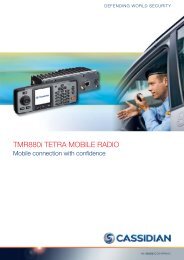
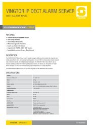
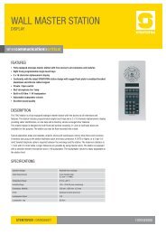
In-building Coverage Solutions<br />
Configuration for in-building area coverage<br />
1) Donor antenna facing the base station (line-of-sight to existing infrastructure)<br />
2) Repeater connected to donor antenna via coaxial cable<br />
3) In-door antennas connected to the repeater via coaxial cable provide coverage on each<br />
floor/room<br />
4) Radiating cable providing coverage in underground area (connected to repeater via<br />
coaxial cable)<br />
10
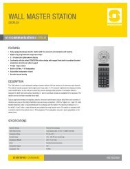
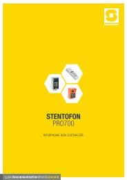
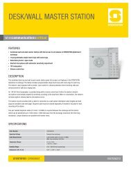
Tunnel Coverage Solutions<br />
Typical configuration for coverage in shorter tunnels<br />
1) Donor antenna facing the BTS antenna (line-of-sight)<br />
2) Main repeater connected to donor antenna via coaxial cable<br />
3) In-line repeaters, basically inserted in a “gap”of the radiating cable<br />
4) Radiating cable carrying RF signals to/from the terminal (mobile or portable)<br />
TBS<br />
RADIATING CABLE<br />
OFF-AIR REPEATER<br />
IN-LINE REPEATERS<br />
11
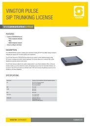
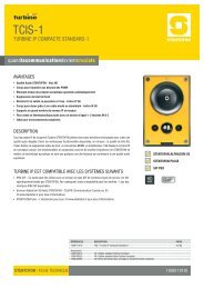
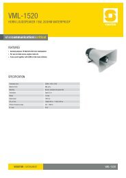
Underground Parking Coverage<br />
Solution<br />
Configuration for underground parking area coverage<br />
1) Base Station on building roof<br />
2) Fibre optic/RF converters installed at both BTS and Repeater<br />
3) Repeater in basement connected via fibre-optic link<br />
4) Radiating cable providing underground transmission<br />
TBS<br />
OFF-AIR<br />
REPEATER<br />
OFF-AIR REPEATER<br />
PARKING ANTENNA<br />
RADIATING CABLE<br />
12
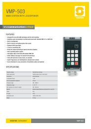
Obstructed Area Solution<br />
Area Configuration extending coverage to shadowed area (re-broadcast)<br />
1) Base Station antenna site<br />
2) Donor antenna having line-of-sight to BS antenna<br />
3) Off-air repeater connected to donor and terminal antennas via coaxial cable<br />
4) Terminal facing antenna<br />
13
Subway Station Coverage<br />
Configuration for underground coverage in subway complex<br />
1) Base Station, providing aboveground coverage.<br />
2) Fibre-optic interfaces connecting base station and each fibre-optic repeater<br />
(creates a robust and “redundant”system)<br />
3) Fibre-optic repeaters<br />
4) Radiating cable<br />
14
TETRA BAND SELECTIVE REPEATERS<br />
OFF-AIR BAND SELECTIVE MINI REPEATER<br />
380-400/410-430 MHz, BW: 5 MHz, max 16 dBm/carrier @ 2 carriers,<br />
max. gain: 70 dBm, wall mount.<br />
Size: 250x410x130 mm<br />
FIBRE-FED HIGH POWER BAND SELECTIVE REPEATER<br />
380-400/410-430 MHz, BW: 5 MHz, max 32 dBm/carrier @ 2 carriers,<br />
max. gain: 80 dB, wall or rack mount.<br />
Size: 500x480x300 mm (wall mount version)<br />
FIBRE-FED LOW POWER BAND SELECTIVE REPEATER<br />
380-400/410-430 MHz, BW: 5 MHz, max 16 dBm/carrier @ 2 carriers,<br />
max. gain: 80 dB, wall or rack mount.<br />
Size: 500x480x300 mm (wall mount version)<br />
OFF-AIR HIGH POWER BAND SELECTIVE REPEATER<br />
380-400/410-430 MHz, BW: 5 MHz, max 32 dBm/carrier @ 2 carriers,<br />
max. gain: 80 dB, wall or rack mount.<br />
Size: 500x480x300 mm (wall mount version)<br />
OFF-AIR LOW POWER BAND SELECTIVE REPEATER<br />
380-400/410-430 MHz, BW: 5 MHz, max 16 dBm/carrier @ 2 carriers,<br />
max. gain: 80 dB, wall or rack mount.<br />
Size: 500x480x300 mm (wall mount version)<br />
IN-LINE HIGH POWER BAND SELECTIVE REPEATER<br />
380-400/410-430 MHz, BW: 5 MHz, max 32 dBm/carrier @ 2 carriers,<br />
max. gain: 70 dB, wall or rack mount.<br />
Size: 500x480x300 mm (wall mount version)<br />
15
IN-LINE LOW POWER BAND SELECTIVE REPEATER<br />
380-400/410-430 MHz, BW: 5 MHz, max 16 dBm/carrier @ 2 carriers,<br />
max. gain: 70 dB, wall or rack mount.<br />
Size: 500x480x300 mm (wall mount version)<br />
FIBRE–OPTICAL MASTER UNIT<br />
380-400/410-430 MHz, up to four repeaters per fibre, up to six fibres per unit.<br />
Size: 483x88x300 mm<br />
BATTERY BACK-UP<br />
4 or 8 hours, alarm, output, automatic recharge.<br />
Size: 400x500x210 mm<br />
FM BROADCAST AMPLIFIER<br />
BRDA 110<br />
BROADBAND REGULATED DOWNLINK AMPLIFIER<br />
Band: 88-108 MHz, max gain 70 dB,<br />
max 19 dBm/carrier @ 2 carriers, RF connectors: N-female.<br />
Size: 300x250x210 mm<br />
VHF REPEATERS<br />
BRUDA 116D<br />
BROADBAND REGULATED UPLINK/DOWNLINK REPEATER<br />
Frequency band: 146-174 MHz, BW: 2-4 MHz, max gain 70 dB,<br />
max. 19 dBm/carrier @ 2 carriers, RF connectors: N-female.<br />
Size: 400x400x210 mm<br />
16
CSRUDA 116D<br />
CHANNEL SELECTIVE REGULATED UPLINK/DOWNLINK REPEATER<br />
Frequency band: 146-174 MHz, max gain: 90 dB, max 29 dBm, RF connectors:<br />
N-female, Size: 400x400x210 mm<br />
UHF REPEATERS<br />
BRUDA 140D<br />
BROADBAND REGULATED UPLINK/DOWNLINK REPEATER<br />
Frequency band: 380-470 MHz, BW: 2-4 MHz, max gain 70 dB,<br />
max. 19 dBm/carrier @ 2 carriers, RF connectors: N-female<br />
Size: 400x400x210 mm<br />
CSRUDA 140D<br />
CHANNEL SELECTIVE REGULATED UPLINK/DOWNLINK AMPLIFIER, UHF<br />
Freq.band: 380 - 470 MHz, max. gain: 90 dB,<br />
max. 29 dBm, RF connectors: N-female.<br />
Size: 400x400x210 mm.<br />
WIDE BAND COUPLERS<br />
HC 10/3<br />
3dB COUPLER<br />
10 - 600 (1000) MHz wideband power splitter. RF-connectors: N-female,<br />
insertion loss 3.5 / 3.5 dB. Max input power 35 dBm.<br />
Size 90 x 50x 25 mm<br />
HC 10/12<br />
HYBRID SPLITTER/COMBINER<br />
10 – 600 MHz, RF connectors: N-female, coupling 1/12 dB (typical),<br />
isolation 40 dB (typical), max input power 37 dBm<br />
Size 90x50x25 mm<br />
17
HC 135<br />
1 TO 3 COUPLER HYBRID SPLITTER/COMBINER<br />
10 – 600 MHz, RF connectors: N-female, coupling 5,4/5,4/5,4 dB (typical),<br />
isolation > 25 dB (typical), max input power 35 dBm<br />
Size 90x50x25 mm<br />
900 MHz BAND COUPLERS<br />
HC 490<br />
1 TO 4 SPLITTER HYBRID COUPLER<br />
815-960 MHz, RF connectors: N-female, insertion loss < 7 dB, isolation 30 dB<br />
(typical), max splitting power 40 dBm<br />
Size 130x80x27 mm<br />
HC 3901<br />
HYBRID COUPLER<br />
815-960 MHz, RF connectors: N-female, coupling 3 dB, insertion loss < 0,5/0,5 dB,<br />
isolation 25 dB (typical), max input power 40 dBm<br />
Size 90x50x25 mm<br />
HC 3901/10<br />
HYBRID COUPLER<br />
815-960 MHz, RF connectors: N-female, coupling 10 dB, isolation 30 dB (typical),<br />
max input power 40 dBm<br />
Size 90x50x25 mm<br />
UHF BAND COUPLERS<br />
HC 3401<br />
HYBRID DIRECTIONAL COUPLER<br />
380 - 470 MHz, RF connectors: N-female, coupling 3 dB,<br />
insertion loss 25 dB (typical), max splitting power 40 dBm<br />
Size: 90x50x25 mm<br />
18
HC 340<br />
HYBRID DIRECTIONAL<br />
380 - 470 MHz, RF connectors: N-female, coupling 3 dB, insertion<br />
loss < 0,3 / 0,7 dB, isolation 25 dB (typical), max input power 47 dBm<br />
Size: 107x63x33 mm<br />
HC340/6<br />
HYBRID DIRECTIONAL COUPLER<br />
380 - 470 MHz, RF connectors: N-female, coupling 1,5 /6 dB (typical),<br />
isolation 25 dB (typical), max input power 47 dBm<br />
Size: 107x63x33 mm<br />
HC 340/8<br />
HYBRID DIRECTIONAL COUPLER<br />
380 - 470 MHz, RF connectors: N-female, coupling 1/8 dB (typical),<br />
isolation 25 dB (typical), max input power 47 dBm<br />
Size: 107x63x33 mm<br />
HC340/12<br />
HYBRID DIRECTIONAL COUPLER<br />
380 - 470 MHz, RF connectors: N-female, coupling 0,5/12 dB (typical),<br />
isolation 25 dB (typical), max input power 47 dBm<br />
Size: 107x63x33 mm<br />
HC340/20<br />
Hybrid directional coupler<br />
380 - 470 MHz, RF connectors: N-female, coupling 0,4/20 dB (typical),<br />
isolation 30 dB (typical), max input power 47 dBm<br />
Size: 107x63x33 mm<br />
HC 440 1 to 4 splitter<br />
HYBRID DIRECTIONAL COUPLER<br />
380 - 470 MHz, RF connectors: N-female, insertion loss < 7 dB (typical),<br />
isolation 30 dB (typical), max splitting power 40 dBm<br />
Size; 130x80x27 mm<br />
19
VHF BAND COUPLERS<br />
HC 316<br />
HYBRID DIRECTIONAL COUPLER<br />
with, 146-174 MHz, RF connectors: N-female, coupling 3 dB,<br />
insertion loss < 0,3/0,7 dB, isolation 25 dB (typical), max input power 47 dBm<br />
Size: 160x63x33 mm<br />
HC 316/6<br />
HYBRID DIRECTIONAL COUPLER<br />
146-174 MHz, RF connectors: N-female, coupling 1,5/6 dB (typical),<br />
isolation 25 dB (typical), max input power 47 dBm<br />
Size: 160x63x33 mm<br />
HC 316/8<br />
HYBRID DIRECTIONAL COUPLER<br />
146-174 MHz, RF connectors: N-female, coupling 1/8 dB (typical),<br />
isolation 25 dB (typical), max input power 47 dBm<br />
Size: 160x63x33mm<br />
HC 316/12<br />
HYBRID DIRECTIONAL COUPLER<br />
146-174 MHz, RF connectors: N-female, coupling 0,5/12 dB (typical),<br />
isolation 25 dB (typical), max input power 47 dBm<br />
Size: 107x63x33mm<br />
HC 316/20<br />
HYBRID DIRECTIONAL COUPLER<br />
146-174 MHz, RF connectors: N-female, coupling 0,4/20 dB (typical),<br />
isolation 30 dB (typical), max input power 47 dBm<br />
Size: 107x63x33mm<br />
20
80 MHz BAND COUPLERS<br />
HC 308<br />
HYBRID DIRECTIONAL COUPLER<br />
68 - 88 MHz, in and out ports: N-female, coupling 3 dB, insertion loss
WIDE BAND RECEIVER SPLITTERS<br />
RXS4<br />
PASSIVE RECEIVER SPLITTER<br />
68-470 MHz, 4 out ports, insertion loss: 7 dB, RF connectors: N-female<br />
Size: 130x80x27 mm<br />
UHF RECEIVER SPLITTERS<br />
AMP8/1<br />
ACTIVE RECEIVER SPLITTER<br />
with redundant amplifier, UHF, gain 16 dB, 1 in port/ 1 out port, LED indication for<br />
each amplifier, RF connectors: N-female, 12 VDC, 150 mA<br />
Size: 130x80x27 mm<br />
AMP8/2<br />
DUAL ACTIVE RECEIVER SPLITTERS<br />
with redundant amplifiers, UHF, gain 16 dB, 1 in port/ 1 out port for each<br />
redundant amplifier, LED indication for each amplifier, RF connectors: N-female,<br />
12 VDC, 150 mA<br />
Size: 130x80x27 mm<br />
AMP8/1-2<br />
Active receiver splitter<br />
with redundant amplifier, UHF, gain 12,5 dB, 1 in port/ 2 out ports, LED indication<br />
for each amplifier, RF connectors: N-female, 12 VDC, 150 mA<br />
Size: 130x80x27 mm<br />
AMP8/1-3<br />
ACTIVE RECEIVER SPLITTER<br />
with redundant amplifier, UHF, gain 10 dB, 1 in port/ 3 out ports, LED<br />
indication for each amplifier, in and out port: N-female, 12 VDC, 150 mA,<br />
Size: 130x80x27 mm<br />
22
AMP8/2-1<br />
DUAL ACTIVE RECEIVER SPLITTERS<br />
with redundant amplifiers, UHF, gain 12,5 dB, 1 in port for each redundant<br />
amplifier and common out port, LED indication for each amplifier,<br />
RF-connectors: N-female, 12 VDC, 150 mA<br />
Size: 130x80x27 mm<br />
AMP8/2-2<br />
DUAL ACTIVE RECEIVER SPLITTERS<br />
with redundant amplifiers, UHF, gain 12, 5 dB, 1 in port for each redundant<br />
amplifier and 2 common out ports, LED indication for each amplifier,<br />
RF connectors: N-female, 12 VDC, 150 mA<br />
Size: 130x80x27 mm<br />
AMP8/2-3<br />
DUAL ACTIVE RECEIVER SPLITTERS<br />
with redundant amplifiers, UHF, gain 10 dB, 1 in port for each redundant<br />
amplifier and 3 common out ports, LED indication for each amplifier,<br />
RF connectors: N-female, 12 VDC, 150 mA<br />
Size: 130x80x27 mm<br />
UHF RECEIVER SPLITTERS<br />
RXS 440<br />
ACTIVE RECEIVER SPLITTER<br />
with redundant amplifier, UHF, Gain 9 dB, 1 in port and 4 out ports: N-female,<br />
LED indication for each amplifier, rack mount<br />
Size: 483x88x120 mm<br />
RXS 840<br />
ACTIVE RECEIVER SPLITTER<br />
with redundant amplifier, UHF, Gain 5,5 dB, 1 in port and 8 out ports: N-female,<br />
LED indication for each amplifier, rack mount<br />
Size: 483x88x120 mm<br />
23
RXS 1240<br />
ACTIVE RECEIVER SPLITTER<br />
with redundant amplifier, UHF, Gain 3 dB, 1 in port and 12 out ports: N-female,<br />
LED indication for each amplifier, rack mount<br />
Size: 483x88x120 mm<br />
VHF RECEIVER SPLITTERS<br />
RXS 416<br />
ACTIVE RECEIVER SPLITTER<br />
with redundant amplifier, VHF, Gain 5 dB, 1 in port and 4 out ports: N-female,<br />
LED indication for each amplifier, rack mount<br />
Size: 483x88x120 mm<br />
RXS 816<br />
ACTIVE RECEIVER SPLITTER<br />
with redundant amplifier, VHF, Gain 2 dB, 1 in port and 8 out ports: N-female,<br />
LED indication for each amplifier, rack mount<br />
Size: 483x88x120 mm<br />
RXS 1216<br />
ACTIVE RECEIVER SPLITTER<br />
with redundant amplifier, VHF, Gain 0 dB, 1 in port and 12 out ports: N-female,<br />
LED indication for each amplifier, rack mount<br />
Size: 483x88x120 mm<br />
UHF TRANSMITTER SUPERVISOR UNITS<br />
TXSU2/40H<br />
TRANSMITTER SUPERVISOR UNIT<br />
UHF, high power, adjustable detection SWR level and low input power,<br />
-40 dB test port, Power interval: 35-45 dBm (forward), 25-35 dBm (reflected),<br />
RF connectors: N-female, test port: BNC<br />
Size: 90x80x22 mm<br />
24
TXSU2/40M<br />
TRANSMITTER SUPERVISOR UNIT<br />
UHF, medium power, adjustable detection SWR level and low input power,<br />
-40 dB test port, Power interval: 25-35 dBm (forward), 15-25 dBm (reflected),<br />
RF connectors: N-female, test port: BNC<br />
Size: 90x80x22 mm<br />
TXSU2/40L<br />
TRANSMITTER SUPERVISOR UNIT<br />
UHF, low power, adjustable detection SWR level and low input power,<br />
-40 dB test port, Power interval: 15-25 dBm (forward), 5-15 dBm (reflected),<br />
RF connectors: N-female, test port: BNC<br />
Size: 90x80x22 mm<br />
VHF TRANSMITTER SUPERVISOR UNITS<br />
TXSU2/16H<br />
TRANSMITTER SUPERVISOR UNIT<br />
VHF, high power, adjustable detection SWR level and low input power,<br />
-40 dB test port, Power interval: 35-45 dBm (forward), 25-35 dBm (reflected),<br />
RF connectors: N-female, test port: BNC<br />
Size: 90x80x22 mm<br />
TXSU2/16M<br />
TRANSMITTER SUPERVISOR UNIT<br />
VHF, medium power, adjustable detection SWR level and low input power,<br />
-40 dB test port, Power interval: 25-35 dBm (forward), 15-25 dBm (reflected),<br />
RF connectors: N-female, test port: BNC<br />
Size: 90x80x22 mm<br />
TXSU2/16L<br />
TRANSMITTER SUPERVISOR UNIT<br />
VHF, low power, adjustable detection SWR level and low input power,<br />
-40 dB test port, Power interval: 15-25 dBm (forward), 5-15 dBm (reflected),<br />
RF connectors: N-female, test port: BNC<br />
Size: 90x80x22 mm<br />
25
RADIATING CABLE SUPERVISOR UNITS<br />
CSU2<br />
CABLE SUPERVISOR UNIT<br />
generating current and measuring cable resistance, insertion loss < 0,4 dB,<br />
RF connectors: TNC female<br />
Size: 73x73x21 mm<br />
CSU3<br />
CABLE SUPERVISOR UNIT<br />
for cable termination and re-connection, insertion loss < 0,4 dB,<br />
RF connectors: N-female<br />
Size: 73x25x25 mm<br />
ATTENUATORS<br />
Att 10<br />
ATTENUATOR 10 dB<br />
10 – 500 MHz, max power: 40 dBm (cont.)/ 47 dBm (peak),<br />
RF connectors: N-female<br />
Size: 90x80x22 mm<br />
Att 10D<br />
TWO PARALLEL ATTENUATORS 10 dB<br />
10 dB, 10 – 500 MHz, max power: 40 dBm (cont.)/ 47 dBm (peak),<br />
RF connectors: N-female<br />
Size: 90x80x22 mm<br />
Att 20<br />
ATTENUATOR 20 dB<br />
10 – 500 MHz, max power: 40 dBm (cont.)/ 47 dBm (peak),<br />
RF connectors: N-female<br />
Size: 90x80x22 mm<br />
26
Att 20D<br />
TWO PARALLEL ATTENUATORS 20 dB<br />
10 – 500 MHz, max power: 40 dBm (cont.)/ 47 dBm (peak),<br />
RF connectors: N-female<br />
Size: 90x80x22 mm<br />
Att 30<br />
ATTENUATOR 30 DB<br />
10 – 500 MHz, max power: 40 dBm (cont.)/ 47 dBm (peak),<br />
RF connectors: N-female<br />
Size: 90x80x22 mm<br />
Att30D<br />
TWO PARALLEL ATTENUATORS 30 dB<br />
10 – 500 MHz, max power: 40 dBm (cont.)/ 47 dBm (peak),<br />
RF connectors: N-female<br />
Size: 90x80x22 mm<br />
Att 40<br />
ATTENUATOR 40 dB<br />
10 – 500 MHz, max power: 40 dBm (cont.)/ 47 dBm (peak),<br />
RF connectors: N-female<br />
Size: 90x80x22 mm<br />
Att 40D<br />
Two parallel attenuators 30 dB<br />
10 – 500 MHz, max power: 40 dBm (cont.)/ 47 dBm (peak),<br />
RF connectors: N-female<br />
Size: 90x80x22 mm<br />
27
www.zenitel.com<br />
Sweden<br />
<strong>Zenitel</strong> Radioteknik AB<br />
Adolfsbergsvägen 29<br />
SE-168 66 Bromma<br />
Tel. +46 8 503 145 50<br />
Fax +46 8 503 145 60<br />
information.sweden@zenitel.com<br />
Finland<br />
<strong>Zenitel</strong> Finland Oy<br />
Vitikka 1 D - Box 68<br />
FIN-02631 Espoo<br />
Tel. +358 943 55 720<br />
Fax +358 952 38 82<br />
info.finland@zenitel.com<br />
Denmark<br />
<strong>Zenitel</strong> Denmark AS<br />
Park Allè 350A<br />
DK-2605 Brøndby<br />
Tel. +45 43 43 74 11<br />
Fax +45 43 43 75 22<br />
info.denmark@zenitel.com<br />
The Netherlands<br />
<strong>Zenitel</strong> Netherlands BV<br />
Microfoonstraat 5<br />
P.O. Box 30350<br />
NL-1322 BN Almere<br />
Tel. +31 36 54 62 600<br />
Fax +31 36 54 62 601<br />
info.netherlands@zenitel.com<br />
Belgium<br />
<strong>Zenitel</strong> Belgium NV<br />
Z.1 Research Park Zellik 110<br />
Pontbeek 63<br />
B-1731 Zellik<br />
Tel. +32 2 370 53 11<br />
Fax +32 2 370 51 19<br />
info.belgium@zenitel.com<br />
Norway<br />
<strong>Zenitel</strong> Norway AS<br />
Sandakerveien 24C, Entrance D9<br />
P.O. Box 4498 Nydalen<br />
NO-0473 Oslo<br />
Tel. +47 40 00 25 00<br />
Fax +47 22 37 85 32<br />
info@zenitel.com<br />
France<br />
<strong>Zenitel</strong> Wireless France SA<br />
20, Parc du Beauvallon BP- 218<br />
FR-57971 Yutz Cedex<br />
Tel. +33 382 82 24 00<br />
Fax +33 382 82 24 24<br />
info.wireless.france@zenitel.com<br />
ZENITEL RADIOTEKNIK<br />
www.zenitel.com<br />
information.sweden@zenitel.com<br />
Radioteknik products are developed and marketed by ZENITEL Radioteknik AB. ZENITEL Radioteknik AB reserves the right to modify designs and specifications without prior notice, in pursuance of<br />
a policy of continuous improvement.<br />
A100K 10389