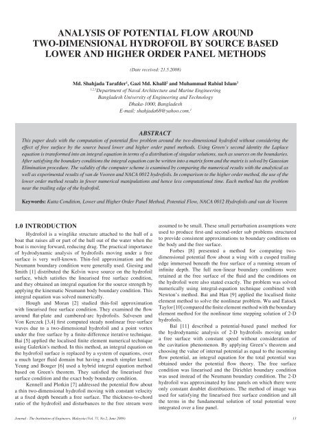
analysis of potential flow around two-dimensional hydrofoil by ... - IEM
analysis of potential flow around two-dimensional hydrofoil by ... - IEM
analysis of potential flow around two-dimensional hydrofoil by ... - IEM

You also want an ePaper? Increase the reach of your titles
YUMPU automatically turns print PDFs into web optimized ePapers that Google loves.
Analysis <strong>of</strong> Potential Flow <strong>around</strong><br />
Two-Dimensional Hydr<strong>of</strong>oil <strong>by</strong> Source Based<br />
Lower and Higher Order Panel Methods<br />
(Date received: 21.5.2008)<br />
Md. Shahjada Tarafder 1 , Gazi Md. Khalil 2 and Muhammad Rabiul Islam 3<br />
1,2,3<br />
Department <strong>of</strong> Naval Architecture and Marine Engineering<br />
Bangladesh University <strong>of</strong> Engineering and Technology<br />
Dhaka-1000, Bangladesh<br />
E-mail: shahjada68@yahoo.com. 1<br />
abstract<br />
This paper deals with the computation <strong>of</strong> <strong>potential</strong> <strong>flow</strong> problem <strong>around</strong> the <strong>two</strong>-<strong>dimensional</strong> hydr<strong>of</strong>oil without considering the<br />
effect <strong>of</strong> free surface <strong>by</strong> the source based lower and higher order panel methods. Using Green’s second identity the Laplace<br />
equation is transformed into an integral equation in terms <strong>of</strong> a distribution <strong>of</strong> singular solutions, such as sources on the boundaries.<br />
After satisfying the boundary conditions the integral equation can be written into a matrix form and the matrix is solved <strong>by</strong> Gaussian<br />
Elimination procedure. The validity <strong>of</strong> the computer scheme is examined <strong>by</strong> comparing the numerical results with the analytical as<br />
well as experimental results <strong>of</strong> van de Vooren and NACA 0012 hydr<strong>of</strong>oils. In comparison to the higher order method, the use <strong>of</strong> the<br />
lower order method results in fewer numerical manipulations and hence less computational time. Each method has the problem<br />
near the trailing edge <strong>of</strong> the hydr<strong>of</strong>oil.<br />
Keywords: Kutta Condition, Lower and Higher Order Panel Method, Potential Flow, NACA 0012 Hydr<strong>of</strong>oils and van de Vooren<br />
1.0 INTRODUCTION<br />
Hydr<strong>of</strong>oil is a winglike structure attached to the hull <strong>of</strong> a<br />
boat that raises all or part <strong>of</strong> the hull out <strong>of</strong> the water when the<br />
boat is moving forward, reducing drag. The practical importance<br />
<strong>of</strong> hydrodynamic <strong>analysis</strong> <strong>of</strong> hydr<strong>of</strong>oils moving under a free<br />
surface is very well-known. Thin-foil approximation and the<br />
Neumann boundary condition were generally used. Giesing and<br />
Smith [1] distributed the Kelvin wave source on the hydr<strong>of</strong>oil<br />
surface, which satisfies the linearised free surface condition,<br />
and they obtained an integral equation for the source strength <strong>by</strong><br />
applying the kinematic Neumann body boundary condition. This<br />
integral equation was solved numerically.<br />
Hough and Moran [2] studied thin-foil approximation<br />
with linearised free surface condition. They examined the <strong>flow</strong><br />
<strong>around</strong> flat-plate and cambered-arc hydr<strong>of</strong>oils. Salvesen and<br />
Von Kerczek [3,4] first computed steady nonlinear free-surface<br />
waves due to a <strong>two</strong>-<strong>dimensional</strong> hydr<strong>of</strong>oil and a point vortex<br />
under the free surface <strong>by</strong> a finite-difference iterative technique.<br />
Bai [5] applied the localised finite element numerical technique<br />
using Galerkin's method. In this method, an integral equation on<br />
the hydr<strong>of</strong>oil surface is replaced <strong>by</strong> a system <strong>of</strong> equations, over<br />
a much larger fluid domain but having a much simpler kernel.<br />
Yeung and Bouger [6] used a hybrid integral equation method<br />
based on Green's theorem. They satisfied the linearised free<br />
surface condition and the exact body boundary condition.<br />
Kennell and Plotkin [7] addressed the <strong>potential</strong> <strong>flow</strong> about<br />
a thin <strong>two</strong>-<strong>dimensional</strong> hydr<strong>of</strong>oil moving with constant velocity<br />
at a fixed depth beneath a free surface. The thickness-to-chord<br />
ratio <strong>of</strong> the hydr<strong>of</strong>oil and disturbances to the free stream were<br />
assumed to be small. These small perturbation assumptions were<br />
used to produce first-and second-order sub problems structured<br />
to provide consistent approximations to boundary conditions on<br />
the body and the free surface.<br />
Forbes [8] presented a method for computing <strong>two</strong><strong>dimensional</strong><br />
<strong>potential</strong> <strong>flow</strong> about a wing with a cusped trailing<br />
edge immersed beneath the free surface <strong>of</strong> a running stream <strong>of</strong><br />
infinite depth. The full non-linear boundary conditions were<br />
retained at the free surface <strong>of</strong> the fluid and the conditions on<br />
the hydr<strong>of</strong>oil were also stated exactly. The problem was solved<br />
numerically using integral-equation technique combined with<br />
Newton’s method. Bai and Han [9] applied the localised finite<br />
element method to solve the nonlinear problem. Wu and Eatock<br />
Taylor [10] compared the finite element method with the boundary<br />
element method for the nonlinear time stepping solution <strong>of</strong> 2-D<br />
hydr<strong>of</strong>oils.<br />
Bal [11] described a <strong>potential</strong>-based panel method for<br />
the hydrodynamic <strong>analysis</strong> <strong>of</strong> 2-D hydr<strong>of</strong>oils moving under<br />
a free surface with constant speed without consideration <strong>of</strong><br />
the cavitation phenomenon. By applying Green’s theorem and<br />
choosing the value <strong>of</strong> internal <strong>potential</strong> as equal to the incoming<br />
<strong>flow</strong> <strong>potential</strong>, an integral equation for the total <strong>potential</strong> was<br />
obtained under the <strong>potential</strong> <strong>flow</strong> theory. The free surface<br />
condition was linearised and the Dirichlet boundary condition<br />
was used instead <strong>of</strong> the Neumann boundary condition. The 2-D<br />
hydr<strong>of</strong>oil was approximated <strong>by</strong> line panels on which there were<br />
only constant doublet distributions. The method <strong>of</strong> image was<br />
used for satisfying the linearised free surface condition and all<br />
the terms in the fundamental solution <strong>of</strong> total <strong>potential</strong> were<br />
integrated over a line panel.<br />
Journal - The Institution <strong>of</strong> Engineers, Malaysia (Vol. 71, No.2, June 2009) 13
Md. Shahjada Tarafder, et al.<br />
Bal [12] addressed steady cavitating <strong>flow</strong>s <strong>around</strong> swept<br />
and V-type hydr<strong>of</strong>oils under a free surface <strong>by</strong> using an iterative<br />
numerical method. The iterative nonlinear numerical method<br />
based on Green’s theorem allowed separating cavitating<br />
hydr<strong>of</strong>oil problem and free surface problem. These <strong>two</strong> problems<br />
were solved separately with the effect <strong>of</strong> one on the other being<br />
accounted for in an iterative manner. Cavitating hydr<strong>of</strong>oil<br />
surface and the free surface were modeled numerically with<br />
constant strength doublet and constant strength source panel.<br />
The source strength on the free surface was expressed in terms<br />
<strong>of</strong> perturbation <strong>potential</strong> <strong>by</strong> applying the free surface condition.<br />
No radiation condition was enforced for the downstream and<br />
transverse boundary on the free surface.<br />
Tarafder et. al. [13] presented the Rankine source panel<br />
for the <strong>potential</strong> <strong>flow</strong> <strong>around</strong> the <strong>two</strong>-<strong>dimensional</strong> body moving<br />
under a free surface. The method <strong>of</strong> image is used to satisfy the<br />
linearised free surface condition. In addition, an iterative panel<br />
method has been applied for surface piercing hydr<strong>of</strong>oils without<br />
cavitation in Hsin and Chou [14]. Kim [15] and Ragab [16]<br />
solved the submerged high speed hydr<strong>of</strong>oil problem without<br />
cavitation.<br />
The aim <strong>of</strong> this paper is to present the basic mathematical<br />
theory behind the lower and higher order source based panel<br />
methods and draw a comparison in order to find the suitable<br />
method for the <strong>analysis</strong> <strong>of</strong> the <strong>potential</strong> <strong>flow</strong> <strong>around</strong> the hydr<strong>of</strong>oils<br />
without considering the effect <strong>of</strong> free surface.<br />
2.0 Mathematical Modelling <strong>of</strong> the<br />
Problem<br />
Consider a hydr<strong>of</strong>oil fixed in a stream <strong>of</strong> uniform <strong>flow</strong><br />
with a velocity Q ∞<br />
as shown in Figure 1. The depth <strong>of</strong> water<br />
from the mean line <strong>of</strong> the hydr<strong>of</strong>oil is h. A Cartesian co-ordinate<br />
system is placed on the free surface and the components <strong>of</strong> the<br />
free stream velocity Q ∞<br />
in the x-z frame <strong>of</strong> reference are U ∞<br />
and<br />
W ∞<br />
respectively. The angle <strong>of</strong> attack α is defined as the angle<br />
between the free stream velocity and the x-axis<br />
W ∞<br />
α = tan -1 ––––<br />
It is assumed that the fluid is inviscid, incompressible and<br />
the <strong>flow</strong> irrotational. The perturbation velocity <strong>potential</strong> φ is<br />
defined <strong>by</strong> Φ = φ + Φ ∞<br />
where, Φ ∞<br />
= U ∞<br />
x + W ∞<br />
z = x Q ∞<br />
cos α + z Q ∞<br />
sin α<br />
Figure 1 : Potential <strong>flow</strong>s over a closed body<br />
(b) The disturbance induced <strong>by</strong> the hydr<strong>of</strong>oil will decay far<br />
from the body<br />
lim∇Φ = Q ∞<br />
(3)<br />
r→∞<br />
which is automatically fulfilled <strong>by</strong> the singular solutions<br />
such as for the source, doublet or the vortex elements.<br />
(c) A proper solution for the doublet distribution will have to<br />
fulfil the Kutta condition at the trailing edge <strong>of</strong> the lifting<br />
body such that the <strong>potential</strong> jump across the wake surface<br />
S W<br />
is the same as the circulation and is constant in the<br />
streamwise direction on S W<br />
. If the velocity <strong>potential</strong> inside<br />
the body surface S B<br />
is defined <strong>by</strong> Φ i<br />
then,<br />
[∆Φ]on S w<br />
= Φ – Φ i<br />
= Γ = Constant<br />
= ∆Φ T.E.<br />
(4)<br />
U ∞<br />
1<br />
The total velocity <strong>potential</strong> Φ ∞<br />
satisfies the Laplace<br />
equation<br />
14<br />
∇ 2 Φ = 0 (1)<br />
in the fluid domain Ω. The domain Ω is bounded <strong>by</strong> the<br />
body surface S B<br />
, wake surface S W<br />
and an outer control surface S ∞<br />
surrounding the body and the wake surface. Now the problem<br />
for the hydr<strong>of</strong>oil can be constructed <strong>by</strong> specifying the boundary<br />
conditions as follows:<br />
(a) The velocity component normal to the solid boundaries <strong>of</strong><br />
the hydr<strong>of</strong>oil must be zero and in a frame <strong>of</strong> reference:<br />
∇Φ . n = 0 (2)<br />
where n is a unit normal vector directed outward from the<br />
fluid domain Ω.<br />
3.0 The General Solution Based on<br />
Green’s Identity<br />
Applying Green’s Second identity the Laplace equation can<br />
be transformed into an integral equation as:<br />
Φ(P) = – ––– ∫s (1n r∇Φ – Φ∇ 1n r).n dS<br />
2π<br />
in which the boundary S is composed <strong>of</strong> S B<br />
, S W<br />
and S ∞<br />
. If<br />
the point <strong>of</strong> singularity lies inside the domain Ω, the velocity<br />
<strong>potential</strong> can be expressed as<br />
Φ(P) = – –––<br />
1<br />
∫s B<br />
(1n r ∇(Φ – Φ i<br />
) – (Φ – Φ i<br />
) ∇ 1n r) . n dS<br />
2π<br />
Journal - The Institution <strong>of</strong> Engineers, Malaysia (Vol. 71, No.2, June 2009)
Analysis <strong>of</strong> Potential <strong>around</strong> Two-Dimensional hydr<strong>of</strong>oil <strong>by</strong> Source Based Lower and Higher Order Panel Methods<br />
1<br />
+ ––– ∫s W<br />
Φ n . ∇ 1n r dS + Φ ∞<br />
(p) (5)<br />
2π<br />
If the difference between the external and internal <strong>potential</strong>s<br />
or the difference between the normal derivative <strong>of</strong> the external<br />
and internal <strong>potential</strong>s <strong>by</strong><br />
– µ = Φ – Φ i<br />
(6)<br />
∂Φ ∂Φ<br />
– σ = ––– – ––– i<br />
(7)<br />
∂n ∂n<br />
the integral equation (5) can be written as<br />
1<br />
∂<br />
Φ(P) = ––– ∫S B<br />
σ 1n r – µ–––(1n r) dS<br />
2π<br />
∂n<br />
– –––<br />
1<br />
∫S W<br />
µ –––<br />
∂<br />
(1n r) dS + Φ ∞<br />
(P) (8)<br />
2π ∂n<br />
The elements µ and σ in Equations (6) and (7) are called<br />
the strength <strong>of</strong> the doublet and source respectively and the minus<br />
sign is a result <strong>of</strong> the normal vector n pointing into S B<br />
. To satisfy<br />
the Neumann boundary condition <strong>of</strong> Equation (2) directly, the<br />
velocity field due to the singularity distribution <strong>of</strong> Equation (8):<br />
is used<br />
1<br />
∇Φ(x, y) = ––– ∫S B<br />
σ∇(1n r) dS<br />
2π<br />
1<br />
∂<br />
– ––– ∫S B<br />
+ S W<br />
µ∇ ––– (1n r) dS + ∇Φ ∞<br />
(9)<br />
2π<br />
∂n<br />
If the singularity distribution strengths σ and µ are known,<br />
then Equation (9) describes the velocity field everywhere (<strong>of</strong><br />
course special treatment is needed when the velocity is evaluated<br />
on the surface S B<br />
). Substitution <strong>of</strong> Equation (9) into the boundary<br />
condition in Equation (2) results in<br />
1<br />
––– ∫S B<br />
σ∇(1n r)dS<br />
2π<br />
1<br />
∂<br />
– ––– ∫S B +<br />
S W<br />
µ∇ –––(1n r) dS + ∇Φ ∞<br />
.n = 0 (10)<br />
2π<br />
∂n<br />
This equation is the basis for many numerical solutions and<br />
should hold for every point on the surface S B<br />
. To construct a<br />
numerical solution the surface S is divided into N panels and the<br />
integration is performed for each panel such that<br />
N<br />
1<br />
––– ∑ ∫S B<br />
σ∇(1n r)dS . n<br />
2π<br />
j=1<br />
N<br />
1<br />
∂<br />
– ––– ∑ ∫S B<br />
µ∇ –––(1n r) dS . n<br />
2π j=1 ∂n<br />
N<br />
1<br />
∂<br />
– ––– ∑ ∫S W<br />
µ∇ –––(1n r) dS . n + ∇Φ ∞<br />
. n = 0 (11)<br />
2π j=1 ∂n<br />
3.1 Lower Order Panel Method<br />
An even simpler lower order panel method (constant<br />
strength source method) can be derived <strong>by</strong> setting the doublet<br />
strength µ to zero in Equation (11). Thus<br />
N<br />
1<br />
––– ∑ ∫S B<br />
σ∇(1n r)dS . n + ∇Φ ∞<br />
. n = 0 (12)<br />
2π<br />
j=1<br />
Now the above equation can be written as<br />
N<br />
∑a ij<br />
σ j<br />
+ ∑∇Φ ∞<br />
. n = 0 (13)<br />
j=1<br />
i=1<br />
N<br />
i=1<br />
where,<br />
–––<br />
1<br />
∫∇(1n r)dS . n i<br />
= (u, w) ij<br />
. n = a (14)<br />
i ij<br />
2π<br />
The influence co-efficient a ij<br />
is defined as the velocity<br />
component normal to the surface. The velocity induced <strong>by</strong> the<br />
panel (u, w) ij<br />
will be calculated <strong>by</strong> using Equations (A10) and<br />
(A11) <strong>of</strong> Appendix. Writing the term Φ ∞<br />
in terms <strong>of</strong> velocity<br />
component, Equation (13) can be written as<br />
N<br />
∑ a ij<br />
σ j<br />
+ ∑(U ∞<br />
, W ∞<br />
) . n i<br />
= 0 (15)<br />
j=1<br />
i = 1<br />
where (U ∞<br />
, W ∞<br />
) = –Q ∞<br />
(cos α, sin α) and n i<br />
= (sin α i<br />
, cos α i<br />
).<br />
For the case <strong>of</strong> symmetric hydr<strong>of</strong>oil W ∞<br />
= 0 and the free stream<br />
normal velocity component is transferred to the right hand side<br />
and the following equation can be written as:<br />
RHS i<br />
= –U ∞<br />
sin α i<br />
(16)<br />
At each collocation point the influences <strong>of</strong> the singularity<br />
elements (a ij<br />
) are calculated and then specifying the boundary<br />
condition for each (i = 1→N)<strong>of</strong> the collocation points results in<br />
a set <strong>of</strong> algebraic equations with the unknown σj (j = 1→N). A<br />
combination <strong>of</strong> Equations (15) and (16) will have the form<br />
a 11<br />
a 12<br />
. . . . . a 1N<br />
σ 1<br />
RHS 1<br />
a 21<br />
a 22<br />
. . . . . a 2N<br />
σ 2<br />
RHS 2<br />
a 31<br />
a 32<br />
. . . . . a 3N<br />
σ 3<br />
RHS 3<br />
. . . . . . . . . .<br />
. . . . . . . . . = .<br />
. . . . . . . . . .<br />
. . . . . . . . . .<br />
a N1<br />
a N2<br />
. . . . . a NN<br />
σ N<br />
RHS N<br />
(17)<br />
The above set <strong>of</strong> algebraic equations has a well-defined<br />
diagonal and can be solved for σ j<br />
<strong>by</strong> using Gaussian elimination<br />
method.<br />
3.1.1. Calculations <strong>of</strong> Pressures and Loads<br />
Once the strengths <strong>of</strong> the sources σ j<br />
is known, the total<br />
tangential velocity Q t<br />
at each collocation point can be calculated<br />
as<br />
N<br />
Q ti<br />
= ∑ (u, w) ij<br />
+ (U ∞<br />
,W ∞<br />
) . t i<br />
(18)<br />
j=1<br />
i = 1<br />
where, t i<br />
= (cos α i<br />
, –sin α i<br />
). Now the pressure coefficient<br />
then becomes<br />
Q 2 t<br />
C p<br />
= 1 – ––– (19)<br />
Q 2 ∞<br />
Note that this method is derived here for non-lifting shapes<br />
and the Kutta condition is not used. Consequently, the circulation<br />
<strong>of</strong> the hydr<strong>of</strong>oil will be zero and hence no lift and drag will be<br />
produced.<br />
Journal - The Institution <strong>of</strong> Engineers, Malaysia (Vol. 71, No.2, June 2009) 15
Md. Shahjada Tarafder, et al.<br />
3.2 Higher order Panel method<br />
The formulation for the higher order panel method (linear<br />
strength source method) can be derived <strong>by</strong> setting the doublet<br />
strength µ to zero in Equation (11)<br />
N<br />
–––<br />
1<br />
∑ ∫σ∇(1n r)dS. n + ∇Φ<br />
2π<br />
∞<br />
. n = 0 (20)<br />
N<br />
j=1<br />
i=1<br />
j=1<br />
Now the above equation can be written as<br />
N<br />
∑ a ij<br />
σ j<br />
+ ∑ ∇Φ ∞<br />
. n i<br />
= 0 (21)<br />
j=1<br />
where the subscripts 1 and 2 refer to the panel edges j and<br />
j+1 respectively. In these Equations σ 0<br />
and σ 1<br />
are the source<br />
strength values, as shown in Figure 3. If the strength <strong>of</strong> σ at the<br />
beginning <strong>of</strong> each panel is set equal to the strength <strong>of</strong> the source<br />
at the end point <strong>of</strong> the previous panel (as shown in Figure 2), a<br />
continuous source distribution is obtained.<br />
where,<br />
1<br />
––– ∫∇(1n r)dS . n<br />
2π<br />
i<br />
= a ij<br />
(22)<br />
The source-only based method will be applicable only to<br />
non-lifting configurations and is considered to be a more refined<br />
model than the one based on constant-strength source elements.<br />
The influence co-efficient a ij<br />
will be calculated as follows:<br />
Figure 3 : Decomposition <strong>of</strong> a generic linear-strength singularity<br />
element.<br />
Now, if the unknowns are the panel edge values <strong>of</strong> the<br />
source distribution (σ j<br />
, σ j<br />
+ 1<br />
, ....... as in Figure 2) then for N<br />
surface panels on a closed body the number <strong>of</strong> unknowns is N+1.<br />
The relation between the source strengths <strong>of</strong> the elements shown<br />
in Figure 3 and the panel edge values is<br />
σ j<br />
= σ 0<br />
σ j +1<br />
= σ 0<br />
+ σ 1<br />
a<br />
(25a)<br />
(25b)<br />
where a is the panel length, and for convenience the<br />
induced-velocity equations are rearranged in terms <strong>of</strong> the paneledge<br />
surface strengths σ j<br />
and σ j+1<br />
(and the subscripts 1 and 2 are<br />
replaced with the j and j+1 subscripts respectively):<br />
σ j<br />
(ξ j+1<br />
– ξ j<br />
) + (σ j+1<br />
– σ j<br />
)(x – ξ j<br />
) r j<br />
u p<br />
= –––––––––––––––––––––––– 1n –––<br />
2π(ξ j+1<br />
– ξ j<br />
)<br />
r j+1<br />
Figure 2 : Nomenclature for a linear-strength surface singularity<br />
element<br />
A segment <strong>of</strong> the discretised singularity distribution on<br />
a solid surface is shown in Figure 2. To establish a normalvelocity<br />
boundary condition based method, the induced-velocity<br />
formulas <strong>of</strong> a constant and a linear-strength source distribution<br />
are combined <strong>by</strong> Equations (A7), (A20), (A8) and (A21) <strong>of</strong><br />
Appendix. The parameters r and θ are shown in Figure 2 and<br />
the velocity (u, w) measured in the panel local coordinate system<br />
p(ξ, η) has components<br />
σ 0<br />
r 2 σ 1<br />
x – ξ 1<br />
r 2 1<br />
1<br />
u p<br />
= ––– 1n ––– + ––– ––––– 1n––– + (ξ<br />
4π 2π 2<br />
1<br />
– ξ 2<br />
) +<br />
r 2 2<br />
σ 0<br />
σ 1<br />
r 1<br />
r 2<br />
z(θ 2<br />
– θ 1<br />
) = ––– + ––– (x – ξ<br />
2π 2π 1<br />
) 1n ––– + –––<br />
2π<br />
[(ξ 1<br />
– ξ 2<br />
) + z(θ 2<br />
– θ 1<br />
)] (23)<br />
r 2 2<br />
σ 1<br />
z (σ j+1<br />
– σ j<br />
) (ξ j+1<br />
– ξ j<br />
)<br />
– ––– –––––––– ––––––––– + (θ<br />
2π (ξ j+1<br />
– ξ j<br />
) z<br />
j+1<br />
– θ j<br />
) (26)<br />
z (σ j+1<br />
– σ j<br />
) r j+1<br />
w p<br />
= ––– –––––––– 1n –––<br />
2π (ξ j+1<br />
– ξ j<br />
)<br />
r j<br />
σ j<br />
(ξ j+1<br />
– ξ j<br />
) + (σ j+1<br />
– σ j<br />
)(x – ξ j<br />
)<br />
+ –––––––––––––––––––––––– + (θ<br />
2π(ξ j+1<br />
– ξ j<br />
)<br />
j+1<br />
– θ j<br />
) (27)<br />
Note that Equations (26) and (27) can be divided into<br />
velocity induced <strong>by</strong> σ j<br />
and <strong>by</strong> σ j+1<br />
such that<br />
(u, w) p<br />
= (u a , w a ) p<br />
+ (u b , w b ) p<br />
(28)<br />
where the subscript ( ) a and ( ) b represent the contribution<br />
due to the leading and trailing singularity strengths, respectively.<br />
If Equations (26) and (27) are arranged we can separate the ( ) a<br />
part <strong>of</strong> the velocity components as,<br />
σ 0<br />
W p<br />
= ––– (θ<br />
2π 2<br />
– θ 1<br />
) + ––– z 1n––– + 2(x – ξ<br />
4π<br />
1<br />
)(θ 2<br />
– θ 1<br />
)<br />
σ 1<br />
r 2<br />
r 1<br />
σ 0<br />
σ 1<br />
r 2 2<br />
r 2 1<br />
= ––– z 1n ––– + ––– (θ<br />
2π<br />
2π 2<br />
– θ 1<br />
) + –––(x – ξ<br />
2π 1<br />
)(θ 2<br />
– θ 1<br />
) (24)<br />
σ 1<br />
a σ j<br />
(ξ j+1<br />
– x) r j<br />
z σ j<br />
u<br />
p<br />
= –––––––––– 1n ––– + ––– (––––––)<br />
2π(ξ j+1<br />
– ξ j<br />
) r j+1<br />
2π ξ j+1<br />
– ξ j<br />
(ξ j+1<br />
– ξ j<br />
)<br />
––––––– + (θ j+1<br />
– θ j<br />
) (29a)<br />
z<br />
16<br />
Journal - The Institution <strong>of</strong> Engineers, Malaysia (Vol. 71, No.2, June 2009)
Analysis <strong>of</strong> Potential <strong>around</strong> Two-Dimensional hydr<strong>of</strong>oil <strong>by</strong> Source Based Lower and Higher Order Panel Methods<br />
z σ r<br />
a<br />
j<br />
j+1<br />
σ j<br />
(ξ j+1<br />
– x)<br />
w = ––– (––––––––) 1n ––– + ––––––––– (θ j+1<br />
– θ j<br />
) (29b)<br />
p<br />
2π (ξ j+1<br />
– ξ j<br />
) 2π(ξ j+1<br />
– ξ j<br />
)<br />
from the ( ) b part <strong>of</strong> the velocity components,<br />
σ r<br />
b j+1<br />
(x – ξ j<br />
) j<br />
u = –––––––––– 1n –––<br />
p<br />
2π(ξ j+1<br />
– ξ j<br />
)<br />
z σ (ξ<br />
j+1 j+1<br />
– ξ j<br />
)<br />
– ––– (––––––) ––––––– + (θ j+1<br />
– θ j<br />
) (29c)<br />
2π ξ j+1<br />
– ξ z<br />
j<br />
z σ r<br />
b<br />
j+1<br />
j+1<br />
σ j+1<br />
(x – ξ j<br />
)<br />
w = – ––– (––––––) 1n ––– + ––––––––– (θ j+1<br />
– θ j<br />
) (29d)<br />
p<br />
2π ξ j+1<br />
– ξ j<br />
r j<br />
2π(ξ j+1<br />
– ξ j<br />
)<br />
To transform these velocity components back to the (x,<br />
z) coordinates, a rotation <strong>by</strong> the panel orientation angle α i<br />
is<br />
performed <strong>by</strong> the following equation:<br />
u<br />
=<br />
cos α i<br />
sin α i<br />
u<br />
w -sin α i<br />
cosα i<br />
w p<br />
(30)<br />
The velocity at each collocation point is influenced <strong>by</strong> the<br />
<strong>two</strong> edges <strong>of</strong> the j-th panel. Thus, adding the influence <strong>of</strong> the<br />
(j+1)-th panel and each subsequent panel gives the local induced<br />
velocity at the first collocation point<br />
(u, w) 1<br />
= (u a , w a ) 11<br />
σ 1<br />
+ [(u b , w b ) 11<br />
+ (u a , w a ) 12<br />
]σ 2<br />
+ [(u b , w b ) 12<br />
+ [(u a , w a ) 13<br />
] σ 3<br />
+ ........<br />
= [(u b , w b ) 1,N-1<br />
+ [(u a , w a ) 1N<br />
]σ N<br />
+ (u b , w b ) 1N<br />
σ N+1<br />
This equation can be reduced to a form<br />
(u, w) 1<br />
= (u, w) 11<br />
σ 1<br />
+ (u, w) 12<br />
σ 2<br />
+ ...... + (u, w) 1N+1<br />
σ<br />
N+1<br />
such that for the first and last terms<br />
(u, w) 11<br />
= (u a , w a ) 11<br />
(u, w) 1,N+1<br />
= (u b , w b ) 1N<br />
σ N+1<br />
and for all other terms<br />
r j+1<br />
(u, w) 1,j<br />
= [(u b , w b ) 1,j–1<br />
+ (u a , w a ) 1,j<br />
] σ j<br />
r j<br />
(31a)<br />
(31b)<br />
(31c)<br />
From this point the procedure is similar to the constantstrength<br />
source method. The influence coefficient is calculated<br />
when σ j<br />
= 1 and<br />
a ij<br />
= (u, w) ij<br />
. n i<br />
(32)<br />
For each collocation point there will be N+1 such coefficients<br />
and unknowns σ j<br />
. The free-stream normal velocity components<br />
RHS i<br />
is found at the collocation point<br />
RHS i<br />
= –U ∞<br />
sin α i<br />
(33)<br />
where α i<br />
is the panel inclination angle. Specification <strong>of</strong><br />
the boundary condition for each (i = 1 → N) <strong>of</strong> the collocation<br />
points result in N linear algebraic equations with the unknowns<br />
σj (j = 1 → N+1). The additional equation can be found <strong>by</strong><br />
requiring that the <strong>flow</strong> leaves parallel to the trailing edge: thus<br />
σ 1<br />
+ σ N+1<br />
= 0 (34)<br />
Another option that will yield similar results is to establish<br />
an additional collocation point slightly behind the trailing edge<br />
and require that the velocity will be zero there (stagnation point<br />
for finite-angle trailing edges). A combination <strong>of</strong> Equation (21),<br />
(33) and (34) with the N boundary conditions result in following<br />
(N+1) linear equations:<br />
a 11<br />
a 12<br />
. . . . . a 1.N+1<br />
σ 1<br />
RHS 1<br />
a 21<br />
a 22<br />
. . . . . a 2.N+1<br />
σ 2<br />
RHS 2<br />
a 31<br />
a 32<br />
. . . . . a 3.N+1<br />
σ 3<br />
RHS 3<br />
. . . . . . . . . .<br />
. . . . . . . . . = .<br />
. . . . . . . . . .<br />
a N1<br />
a N2<br />
. . . . . a N.N+1<br />
σ N<br />
RHS N<br />
1 0 . . . . . 1 σ N+1<br />
0 (35)<br />
The above set <strong>of</strong> algebraic equations has a well-defined<br />
diagonal and can be solved for σ j<br />
<strong>by</strong> using standard methods <strong>of</strong><br />
linear algebra.<br />
3.2.1. Calculation <strong>of</strong> Pressures and Loads<br />
Once the strength <strong>of</strong> the sources σ j<br />
is known, the velocity<br />
at each collocation point can be calculated and the pressure<br />
coefficient can be calculated <strong>by</strong> using Equation (19).<br />
4.0 Results and Discussions<br />
The numerical algorithms outlined before have been applied<br />
to a number <strong>of</strong> hydr<strong>of</strong>oils such as van de Vooren and NACA 0012<br />
in order to analyse the hydrodynamic characteristics at various<br />
depths <strong>of</strong> water. In the first case, source based lower order panel<br />
method with Neumann boundary condition is applied to the<br />
15% thick symmetric van de Vooren hydr<strong>of</strong>oil with an angle <strong>of</strong><br />
attack, α = 0°. The hydr<strong>of</strong>oil is discretised <strong>by</strong> M = 90 panels.<br />
The predicted pressure on van de Vooren hydr<strong>of</strong>oil is compared<br />
with its analytical results in Figure 4 and the agreement is quite<br />
satisfactory. The pressures on this hydr<strong>of</strong>oil at various depths <strong>of</strong><br />
water such as respectively are plotted in Figure 5 and we can see<br />
that the effect <strong>of</strong> the depths <strong>of</strong> water is insignificant. Discretising<br />
the hydr<strong>of</strong>oil <strong>by</strong> 40, 90 and 180 panels respectively, source based<br />
lower order panel method has also been applied to van de Vooren<br />
hydr<strong>of</strong>oil at a depth <strong>of</strong> water h/c = 0.4. Note that this method<br />
is derived here for nonlifting shapes and the Kutta condition is<br />
not used. Consequently, the circulation <strong>of</strong> the hydr<strong>of</strong>oil will be<br />
zero and hence no lift and drag will be produced. However, the<br />
pressure distribution is well predicted in Figure 6 and they are<br />
convergent to one another. The numerical solution presented<br />
here does not assume a symmetric solution. But it appears that<br />
the solution is symmetric about the x-axis and the number <strong>of</strong><br />
unknowns can be reduced <strong>by</strong> M/2 <strong>by</strong> a minor modification in the<br />
process <strong>of</strong> influence co-efficient.<br />
A comparison <strong>of</strong> pressure distribution on van de Vooren<br />
hydr<strong>of</strong>oil with an angle <strong>of</strong> attack, α = 0° calculated from source<br />
based higher order panel method is drawn in Figure 7. It is<br />
noted that each computational method depends on the grid and<br />
on various other parameters. Therefore, each technique must be<br />
validated first before it can be applied to unknown cases. The<br />
sensitivity <strong>of</strong> the linear higher order panel method with Neumann<br />
boundary condition is presented in Figure 8. Both methods will<br />
have problems near the trailing edge. The calculated values <strong>of</strong><br />
C p<br />
on NACA 0012 hydr<strong>of</strong>oil are also compared with Fletcher’s<br />
numerical as well as Amick’s experimental results (Fletcher,<br />
1991) in Figure 9. The agreement between the experimental<br />
Journal - The Institution <strong>of</strong> Engineers, Malaysia (Vol. 71, No.2, June 2009) 17
Md. Shahjada Tarafder, et al.<br />
result and that <strong>of</strong> lower order method is better in compared<br />
to higher order method. Higher order method can achieve a<br />
prescribed level <strong>of</strong> accuracy but the code is more complicated<br />
and the required amount <strong>of</strong> computation per panel is higher.<br />
However, the relative merits <strong>of</strong> low and high order methods<br />
depend on the specific problem and on the fundamental method<br />
being used.<br />
The computation times measured in seconds (<strong>of</strong> Intel<br />
Celeron computer, 2.00 GHZ and 248 MB <strong>of</strong> RAM) versus<br />
the number <strong>of</strong> panels is presented in Figure 10. These data<br />
indicate that the lower order panel method is the faster and<br />
computational effort increases with increasing the order <strong>of</strong> the<br />
method.<br />
Figure 6 : Panel size effect on the pressure on van de Vooren hydr<strong>of</strong>oil<br />
at h/c = 0.4 <strong>by</strong> the lower order panel method<br />
Figure 4 : Pressure on van de Vooren hydr<strong>of</strong>oil at h/c = 0 <strong>by</strong> the lower<br />
order panel method<br />
Figure 7 : Pressure on van de Vooren hydr<strong>of</strong>oil at h/c = 0 <strong>by</strong> the<br />
higher order panel method<br />
Figure 5 : Water depth effect on the pressure on van de Vooren<br />
hydr<strong>of</strong>oil <strong>by</strong> the lower order panel method<br />
Figure 8 : Panel size effect on the pressure on van de Vooren hydr<strong>of</strong>oil<br />
at h/c = 0 <strong>by</strong> the higher order panel method<br />
18<br />
Journal - The Institution <strong>of</strong> Engineers, Malaysia (Vol. 71, No.2, June 2009)
Analysis <strong>of</strong> Potential <strong>around</strong> Two-Dimensional hydr<strong>of</strong>oil <strong>by</strong> Source Based Lower and Higher Order Panel Methods<br />
Figure 9 : Comparison between calculated and experimental Pressures<br />
on NACA 0012 hydr<strong>of</strong>oils at h/c = 0<br />
5.0 Conclusions<br />
The paper deals with the source based lower and higher<br />
order panel methods for computing the <strong>potential</strong> <strong>flow</strong> <strong>around</strong> the<br />
hydr<strong>of</strong>oil moving with a uniform speed in an unbounded fluid.<br />
The following conclusions can be drawn from the present study:<br />
(i)<br />
In general, the use <strong>of</strong> the lower order method results in fewer<br />
numerical manipulations and hence less computational<br />
time. The use <strong>of</strong> higher order method requires more<br />
computational effort and is justified when the velocity near<br />
the body is continuous.<br />
Figure 10 : Comparison <strong>of</strong> CPU time for Lower and higher order<br />
panel methods<br />
(ii) Each computational method depends on the grid and on<br />
various other parameters. Therefore, each technique must<br />
be validated before it is applied to unknown cases.<br />
(iii) Both the methods have the problems near the cusped trailing<br />
edge <strong>of</strong> the hydr<strong>of</strong>oil. Such problems may be avoided <strong>by</strong><br />
modeling a finite angle there (instead <strong>of</strong> zero angle) and<br />
this may be achieved <strong>by</strong> simply having larger trailing-edge<br />
panels.<br />
(iv) The agreement between the present numerical results<br />
with the analytical as well as experimental results is quite<br />
satisfactory. <br />
Appendix<br />
Influence Co-efficient<br />
Lower Order Panel Method<br />
Consider a source distribution along the ξ axis as shown in<br />
Figure 11. It is assumed that the source strength per unit length<br />
is constant such that σ (ξ) = σ = const. The influence <strong>of</strong> this<br />
distribution at a point P (x, z) is an integral <strong>of</strong> the influences <strong>of</strong><br />
the point elements along the segment ξ 1<br />
– ξ 2<br />
(see Islam, 2008):<br />
ξ 2<br />
σ<br />
Φ = ––– ∫ 1n (x – ξ) 2 + z 2 dξ (A1)<br />
2π ξ 1<br />
Differentiating Equation (A1) with respect to x and z<br />
ξ 2<br />
σ x – ξ<br />
u(ξ, η) = ––– ∫ –––––––––– dξ<br />
2π (x – ξ) 2 + z 2<br />
ξ 1<br />
ξ 2<br />
w(ξ, η) = –––<br />
σ<br />
∫ ––––––––––<br />
z<br />
dξ<br />
2π ξ (x – ξ) 2 + z 2<br />
1<br />
(A2)<br />
(A3)<br />
Figure 11: Constant-strength source distributions along the x - axis.<br />
The integral for the velocity <strong>potential</strong> in terms <strong>of</strong> the corner<br />
points (ξ 1<br />
, 0) and (ξ 2<br />
, 0) <strong>of</strong> a generic panel element as shown in<br />
Figure 12, the distances r 1<br />
, r 2<br />
and the angles θ 1<br />
, θ 2<br />
it becomes<br />
σ<br />
Φ = ––– [(x – ξ 1<br />
) 1n r 2 – (x – ξ ) 1n 1 2 r2 + 2z(θ – θ )] (A4)<br />
4π<br />
2 2 1<br />
where<br />
z<br />
θ k<br />
= tan -1 ––––– k = 1, 2 (A5)<br />
x – ξ k<br />
Journal - The Institution <strong>of</strong> Engineers, Malaysia (Vol. 71, No.2, June 2009) 19
Md. Shahjada Tarafder, et al.<br />
r k<br />
= (x – ξ k<br />
) 2 + z 2 k = 1, 2 (A6)<br />
Figure 12 : Nomenclature for the panel influence coefficient<br />
derivation<br />
The velocity components are obtained from Equation (A2)<br />
and (A3) as<br />
r 1<br />
σ σ r 2 1<br />
u = ––– 1n ––– = ––– 1n –––<br />
2π r 2 4π<br />
σ<br />
w = ––– (θ 2<br />
– θ 1<br />
)<br />
2π<br />
Returning to x, z variables we obtain<br />
σ<br />
Φ = ––– {(x – ξ 1<br />
) 1n[(x – ξ 1<br />
) 2 + z 2 ]<br />
4π<br />
– (x – ξ 2<br />
) 1n[(x – ξ 2<br />
) 2 + z 2<br />
(A7)<br />
(A8)<br />
z<br />
z<br />
+ 2z (tan -1 ––––– – tan -1 –––––)} (A9)<br />
x – ξ 2<br />
x – ξ 1<br />
σ (x – ξ<br />
u = ––– 1n –––––––––– 1<br />
) 2 + z 2<br />
4π (x – ξ 2<br />
) + z 2<br />
r 2 2<br />
σ z<br />
z<br />
w = ––– tan -1 ––––– – tan -1 –––––<br />
2π x – ξ 2<br />
x – ξ 1<br />
Higher Order Panel Method<br />
(A10)<br />
(A11)<br />
Let us consider a linear source distribution along the ξ<br />
axis (ξ 1<br />
Analysis <strong>of</strong> Potential <strong>around</strong> Two-Dimensional hydr<strong>of</strong>oil <strong>by</strong> Source Based Lower and Higher Order Panel Methods<br />
σ 1<br />
x (x – ξ<br />
u = ––– –– 1n –––––––––– 1<br />
) 2 + z 2<br />
+ (ξ 1<br />
– ξ 2<br />
)<br />
2π 2 (x – ξ 2<br />
) 2 + z 2<br />
z<br />
z<br />
+ z tan -1 ––––– – tan -1 ––––– (A19)<br />
x – ξ 2<br />
x – ξ 1<br />
σ 1<br />
(x – ξ<br />
w = ––– z 1n –––––––––– 1<br />
) 2 + z 2<br />
4π (x – ξ 2<br />
) 2 + z 2<br />
z<br />
z<br />
+ 2x tan -1 ––––– – tan -1 ––––– (A20)<br />
x – ξ 2<br />
x – ξ 1<br />
References<br />
[1] Giesing, J.P. and Smith, A.M.O. (1967): Potential <strong>flow</strong> about<br />
<strong>two</strong>-<strong>dimensional</strong> hydr<strong>of</strong>oils, Journal <strong>of</strong> Fluid Mechanics,<br />
Vol. 28, pp.113-129.<br />
[2] Hough, G.R. and Moran, S.P. (1969): Froude number effects<br />
on <strong>two</strong>-<strong>dimensional</strong> hydr<strong>of</strong>oils, Journal <strong>of</strong> Ship Research,<br />
Vol.13, pp.53-60.<br />
[3] Salvesen and Von Kerczek, C. (1975): Numerical solution<br />
<strong>of</strong> <strong>two</strong>-<strong>dimensional</strong> nonlinear body-wave problems.<br />
Proceedings, 1 st International Conference on Numerical<br />
Ship Hydrodynamics, Bethesda, pp. 279-293.<br />
[4] Salvesen and Von Kerczek, C. (1976): Comparison <strong>of</strong><br />
numerical and perturbation solution <strong>of</strong> <strong>two</strong>-<strong>dimensional</strong><br />
nonlinear water-wave problems, Journal <strong>of</strong> Ship Research,<br />
Vol. 20(3), pp.160-170.<br />
[5] Bai, K.J. (1978): A localized finite-element method for<br />
<strong>two</strong>-<strong>dimensional</strong> steady <strong>potential</strong> <strong>flow</strong>s with a free surface,<br />
Journal <strong>of</strong> Ship Research, Vol. 22, pp.216-230.<br />
[6] Yeung, R.W. and Bouger, Y.C. (1979): A hybrid-integral<br />
equation method for steady <strong>two</strong>-<strong>dimensional</strong> ship waves,<br />
International Journal <strong>of</strong> Numerical Methods in Engineering,<br />
Vol.14, pp.317-336.<br />
[7] Kennell, C. and Plotkin, A. (1984): A second order theory<br />
for the <strong>potential</strong> <strong>flow</strong> about thin hydr<strong>of</strong>oils, Journal <strong>of</strong> Ship<br />
Research, Vol. 28, pp.55-64.<br />
[8] Forbes, L.K. (1985): A numerical method for non-linear<br />
<strong>flow</strong> about a submerged hydr<strong>of</strong>oil, Journal <strong>of</strong> Engineering<br />
Mathematics, Vo.19, pp.329-339.<br />
[9] Bai, K.J. and Han, J.H. (1994): A localized finite element<br />
method for the nonlinear steady waves due to a <strong>two</strong><strong>dimensional</strong><br />
hydr<strong>of</strong>oil, Journal <strong>of</strong> Ship Research, Vol.38,<br />
pp.42-51.<br />
[10] Wu, G.K. and Eatock Taylor, R. (1995): Time stepping<br />
solutions <strong>of</strong> the <strong>two</strong> <strong>dimensional</strong> nonlinear wave radiation<br />
problem, International Journal <strong>of</strong> Ocean Engineering,<br />
Vol.22, pp.785-798.<br />
[11] Bal, S. (1999): A panel method for the <strong>potential</strong> <strong>flow</strong> <strong>around</strong><br />
2-D hydr<strong>of</strong>oil, Transactions <strong>of</strong> Journal <strong>of</strong> Engineering and<br />
Environmental Science, Vol. 23, pp.349-361.<br />
[12] Bal, S. (2005): Lift and drag characteristics <strong>of</strong> cavitating<br />
swept and V-type hydr<strong>of</strong>oils, International Journal <strong>of</strong><br />
Maritime Engineering, The Royal Institute <strong>of</strong> Naval<br />
Architects.<br />
[13] Tarafder, M. S., Khalil, G. M. and Mahmud, S. M. I. (2006):<br />
Free surface <strong>potential</strong> <strong>flow</strong> <strong>around</strong> Hydr<strong>of</strong>oils <strong>by</strong> Rankine<br />
source panel method, The Journal <strong>of</strong> National Oceanographic<br />
and Maritime Institute, Vol. 23, No. 2, pp.57-75.<br />
[14] Hsin, C.Y. and Chou, S.K. (1998): Applications <strong>of</strong> a hybrid<br />
boundary element method to the <strong>analysis</strong> <strong>of</strong> free surface<br />
<strong>flow</strong> <strong>around</strong> lifting and non-lifting bodies, Proceedings <strong>of</strong><br />
the 22 nd Sympossium on Naval Hydrodynamics, Washington<br />
DC, USA.<br />
[15] Kim, B.K. (1992): Computation <strong>of</strong> hydrodynamic forces on a<br />
submerged lifting body, Proceedings <strong>of</strong> the 2 nd International<br />
Offshore and Polar Engineering Conference, ISOPE, San<br />
Francisco, USA, June 14-19, pp 367-374.<br />
[16] Ragab, S.A. (1998): Inviscid non-cavitating <strong>flow</strong> over<br />
shallowly submerged swept hydr<strong>of</strong>oils, Proceedings <strong>of</strong> the<br />
8 th International Offshore and Polar Engineering Conference,<br />
ISOPE, Montreal, Canada, May 24-29, pp. 253-259.<br />
PROFILES<br />
Dr Md Shahjada Tarafder<br />
Dr Md. Shahjada Tarafder is now working as an Associate<br />
Pr<strong>of</strong>essor in the Department <strong>of</strong> Naval Architecture<br />
and Marine Engineering <strong>of</strong> Bangladesh University <strong>of</strong><br />
Engineering and Technology, Dhaka. Dr Tarafder obtained<br />
the Degree <strong>of</strong> B Sc Engg. in 1994 and M Sc Engg. in 1996<br />
from the same university. He obtained the Degree <strong>of</strong> Doctor<br />
<strong>of</strong> Engineering from Yokohama National University, Japan<br />
in September 2002.<br />
Dr Gazi M Khalil<br />
Dr Gazi M. Khalil is serving as a Pr<strong>of</strong>essor in the Department<br />
<strong>of</strong> Naval Architecture and Marine Engineering <strong>of</strong> Bangladesh<br />
University <strong>of</strong> Engineering and Technology, Bangladesh. He<br />
has been teaching and doing research in this university for more<br />
than 35 years. Dr Khalil has to his credit more than 100 research<br />
papers published in various national and international journals<br />
and proceedings <strong>of</strong> the conferences. He has been serving as<br />
the Editor <strong>of</strong> the Journal <strong>of</strong> NOAMI published <strong>by</strong> the National<br />
Oceanographic and Maritime Institute, Bangladesh since 1997<br />
to till to-date.<br />
Mr. Muhammad Rabiul Islam<br />
Mr. Muhammad Rabiul Islam is an Assistant Naval Architect<br />
<strong>of</strong> Bangladesh Inland Water Transport Authority (BIWTA),<br />
Ministry <strong>of</strong> Shipping <strong>of</strong> Bangladesh. Currently, he is doing his<br />
Ph D in Yokohama National University, Japan. He received the<br />
Degree <strong>of</strong> M Sc Engg. in 2008 and B Sc Engg. in 2003 from the<br />
Department <strong>of</strong> Naval Architecture and Marine Engineering <strong>of</strong><br />
Bangladesh University <strong>of</strong> Engineering & Technology, Dhaka.<br />
Journal - The Institution <strong>of</strong> Engineers, Malaysia (Vol. 71, No.2, June 2009) 21