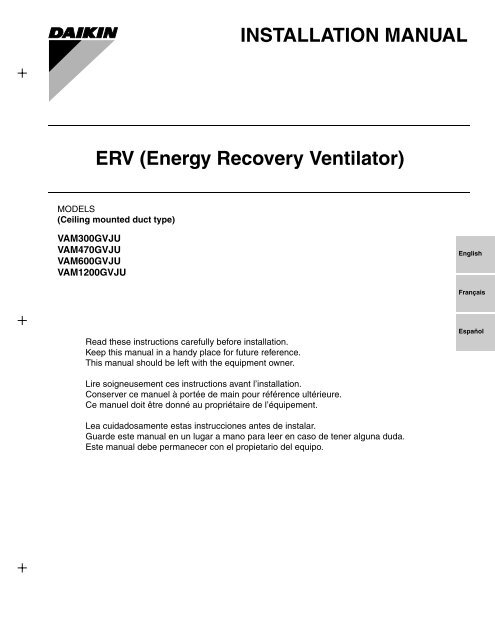
INSTALLATION MANUAL ERV (Energy Recovery ... - Daikin AC
INSTALLATION MANUAL ERV (Energy Recovery ... - Daikin AC
INSTALLATION MANUAL ERV (Energy Recovery ... - Daikin AC

Create successful ePaper yourself
Turn your PDF publications into a flip-book with our unique Google optimized e-Paper software.
<strong>INSTALLATION</strong> <strong>MANUAL</strong><br />
<strong>ERV</strong> (<strong>Energy</strong> <strong>Recovery</strong> Ventilator)<br />
MODELS<br />
(Ceiling mounted duct type)<br />
VAM300GVJU<br />
VAM470GVJU<br />
VAM600GVJU<br />
VAM1200GVJU<br />
English<br />
Français<br />
Read these instructions carefully before installation.<br />
Keep this manual in a handy place for future reference.<br />
This manual should be left with the equipment owner.<br />
Español<br />
Lire soigneusement ces instructions avant l’installation.<br />
Conserver ce manuel à portée de main pour référence ultérieure.<br />
Ce manuel doit être donné au propriétaire de l’équipement.<br />
Lea cuidadosamente estas instrucciones antes de instalar.<br />
Guarde este manual en un lugar a mano para leer en caso de tener alguna duda.<br />
Este manual debe permanecer con el propietario del equipo.
• VAM300GVJU, VAM470GVJU, VAM600GVJU<br />
• VAM1200GVJU<br />
2-11/16<br />
24 or more<br />
6~10<br />
4<br />
1<br />
3<br />
2<br />
5<br />
26 or more<br />
8~12<br />
4<br />
1<br />
3<br />
2<br />
5<br />
10<br />
11<br />
9<br />
12<br />
4<br />
13/16<br />
2<br />
7<br />
8<br />
6<br />
15<br />
10<br />
11<br />
8-7/16<br />
13-3/4<br />
13<br />
40-11/16<br />
9<br />
12 6<br />
2 13<br />
3-3/4 5-1/8 10 10<br />
6-5/16<br />
8-7/16<br />
13/16<br />
5-1/8<br />
7<br />
8<br />
6-5/16<br />
13<br />
14<br />
30-7/8<br />
8-7/16<br />
(in.)<br />
Model name A B C D E F G H J K L M N<br />
VAM300GVJU 34-5/8 31-1/2 12-1/16 3-5/16 32-3/8 33-7/16 5-3/8 16-3/8 7-3/16 5-3/16 4-13/16 7-3/4 8-3/8<br />
VAM470GVJU 43-11/16 32-3/4 15-1/4 3-1/2 40-11/16 34-3/4 6 16-15/16 9-1/4 6 6-7/16 9-11/16 10-3/8<br />
VAM600GVJU 43-11/16 47-13/16 15-1/4 3-1/2 40-11/16 49-3/4 6 24-1/2 9-1/4 6 6-7/16 9-11/16 10-3-8<br />
VAM1200GVJU 43-11/16 47-13/16 – – – 49-5/8 – 19-5/8 – – – – –<br />
1<br />
21-1/2<br />
4<br />
14<br />
21-1/2<br />
8-7/16<br />
100 or higher from the floor<br />
for installation in high places<br />
2<br />
[1]
100 or higher from the floor<br />
for installation in high places<br />
4 (φ10)<br />
3<br />
2 3<br />
4 (φ14)<br />
1<br />
18<br />
7 8<br />
11<br />
VAM1200GVJU<br />
9<br />
17<br />
18<br />
6<br />
10<br />
1<br />
18<br />
1<br />
18<br />
13<br />
12<br />
14<br />
9 11<br />
15 15 16<br />
100 or higher from the floor<br />
for installation in high places<br />
Floor<br />
2<br />
9 11<br />
4<br />
[2]
VAM300GVJU<br />
VAM470GVJU<br />
VAM600GVJU<br />
VAM1200GVJU<br />
<strong>ERV</strong> (<strong>Energy</strong> <strong>Recovery</strong> Ventilator)<br />
Installation manual<br />
CONTENTS<br />
1. SAFETY CONSIDERATIONS ...................................... 1<br />
2. BEFORE <strong>INSTALLATION</strong> ............................................ 2<br />
3. SELECTING <strong>INSTALLATION</strong> SITE ............................. 3<br />
4. PREPARATIONS BEFORE <strong>INSTALLATION</strong> ............... 3<br />
5. THE METHOD OF <strong>INSTALLATION</strong> ............................. 4<br />
6. DUCT CONNECTION .................................................. 5<br />
7. SYSTEM ...................................................................... 6<br />
8. ELECTRIC WIRING WORK ......................................... 8<br />
9. FIELD SETTING AND TEST RUN ............................. 13<br />
10.DESCRIPTION OF SYSTEM<br />
AND APPLICABLE PATTERNS ................................ 15<br />
1. SAFETY CONSIDERATIONS<br />
Read these “SAFETY CONSIDERATIONS for Installation”<br />
carefully before installing the <strong>ERV</strong> unit. After completing the<br />
installation, make sure that the unit operates properly during a<br />
test run.<br />
Instruct the customer on how to operate and maintain the unit.<br />
Inform the customer that this Installation Manual should be<br />
kept with the Operation Manual for future reference.<br />
Always use a licensed installer or contractor to install this product.<br />
Improper installation can result in water or refrigerant leakage,<br />
electrical shock, fire or explosion.<br />
Meanings of DANGER, WARNING, CAUTION and NOTE Symbols:<br />
DANGER.................Indicates an imminently hazardous<br />
situation which, if not avoided, will<br />
result in death or serious injury.<br />
WARNING ...............Indicates a potentially hazardous situation<br />
which, if not avoided, could result<br />
in death or serious injury.<br />
CAUTION ................Indicates a potentially hazardous situation<br />
which, if not avoided, may result<br />
in minor or moderate injury.<br />
It may also be used to alert against<br />
unsafe practices.<br />
NOTE ......................Indicates situations that may result in<br />
equipment or property-damage accidents<br />
only.<br />
DANGER<br />
• Do not ground units to water pipes, gas pipes, telephone<br />
wires or lightning rods as incomplete grounding<br />
can cause a severe shock hazard resulting in severe<br />
injury or death. Additionally, grounding to gas pipes<br />
could cause a gas leak and potential explosion causing<br />
severe injury or death.<br />
• Do not install unit in an area where flammable materials<br />
are present due to risk of explosions that can cause<br />
serious injury or death.<br />
• Safely dispose all packing and transportation materials<br />
in accordance with federal/state/local laws or ordinances.<br />
Packing materials such as nails, other metal or<br />
wood parts, including plastic packing materials used for<br />
transportation may cause injuries or death by suffocation.<br />
WARNING<br />
• Only qualified personnel must carry out the installation<br />
work. Installation must be done in accordance with this<br />
installation manual. Improper installation may result in<br />
water leakage, electric shock or fire.<br />
• Use only specified accessories and parts for installation<br />
work. Failure to use specified parts may result in<br />
water leakage, electric shocks, fire or the unit falling.<br />
• Install the unit on a foundation strong enough that it<br />
can withstand the weight of the unit. A foundation of<br />
insufficient strength may result in the unit falling and<br />
causing injuries.<br />
• Take into account strong winds, typhoons or earthquakes<br />
when installing. Improper installation may result<br />
in the unit falling and causing accidents.<br />
• Make sure that a separate power supply circuit is provided<br />
for this unit and that all electrical work is carried<br />
out by qualified personnel according to local state and<br />
national regulations. An insufficient power supply<br />
capacity or improper electrical construction may lead to<br />
electric shocks or fire.<br />
• Make sure that all wiring is secured, that specified wires<br />
are used and that no external forces act on the terminal<br />
connections or wires. Improper connections or installation<br />
may result in fire.<br />
• When wiring, position the wires so that the control box<br />
cover can be securely fastened. Improper positioning of<br />
the control box cover may result in electric shocks, fire<br />
or the terminals overheating.<br />
• Before touching electrical parts, turn off the unit.<br />
• Be sure to install a ground fault circuit interrupter if one<br />
is not already available. This helps prevent electrical<br />
shocks or fire.<br />
• Do not change the setting of the protection devices. If the<br />
pressure switch, thermal switch or other protection device<br />
is shorted and operated forcibly, or parts other than those<br />
specified by <strong>Daikin</strong> are used, fire or explosion may occur.<br />
• Locate the outdoor air intake vent so that it does not<br />
take in exhaust air which contains combustion air, etc.<br />
Incorrect installation may cause a loss of oxygen in the<br />
room, leading to serious accidents.<br />
• Install the two outdoor ducts with down slope to prevent<br />
rainwater from entering the unit.<br />
If this is not done completely, water may enter the building,<br />
may damage furniture, and cause electric shocks and fire.<br />
• Insulate the duct and the wall electrically when a metal<br />
duct is to be penetrated through the metal lattice and<br />
wire lattice or metal lining of a wooden structure wall.<br />
Improper duct work may cause electric shocks or fire.<br />
• Make sure the temperature and humidity near the unit<br />
and the air suction/discharge air grille is within limit dictated<br />
by the usage conditions.<br />
1. Refrigerated truck or other locations with low temperatures.<br />
2. Place such as bathroom or heated pools subjected to<br />
moisture.<br />
This may cause fires or electric leak or electric shocks.<br />
• Make sure that a snow protection measure is taken. If no<br />
protection snow may enter through the outdoor ducts, and<br />
cause damaging furniture and electric shock and fire.<br />
1 English
CAUTION<br />
• Do not touch the switch with wet fingers. Touching a<br />
switch with wet fingers can cause electric shock.<br />
• Do not allow children to play on or around the unit to<br />
prevent injury.<br />
• Be careful when transporting the product.<br />
• Do not install the unit in the following locations:<br />
(a) Where a mineral oil mist or oil spray or vapor is produced,<br />
for example, in a kitchen.<br />
Plastic parts may deteriorate and fall off or result in<br />
water leakage.<br />
(b) Where corrosive gas, such as sulfurous acid gas, is<br />
produced.<br />
Corroding copper pipes or soldered parts may result<br />
in damage.<br />
(c) Near machinery emitting electromagnetic waves.<br />
Electromagnetic waves may disturb the operation of<br />
the control system and cause the unit to malfunction.<br />
(d) Where flammable gas may leak, where there is carbon<br />
fiber or ignitable dust suspension in the air, or<br />
where volatile flammables such as thinner or gasoline<br />
are handled. Operating the unit in such conditions<br />
can cause a fire.<br />
• Do not allow exhaust air to enter the outdoor air intake<br />
vent.<br />
This may cause the air of the room to become contaminated,<br />
harming the health.<br />
NOTE<br />
• Install the power supply and control wires for the unit at<br />
least 3.3 feet away from televisions or radios to prevent<br />
image interference or noise. Depending on the radio<br />
waves, a distance of 3.3 feet may not be sufficient to<br />
eliminate the noise.<br />
• Dismantling the unit and additional parts must be done<br />
in accordance with the relevant local, state and national<br />
regulations.<br />
• This unit is an appliance that should not be accessible<br />
to the general public.<br />
• Insulate the two outdoor ducts and the supply air duct<br />
to prevent condensation.<br />
If this is not done completely, water may enter the building,<br />
may damage furniture, etc.<br />
• In areas where insects are easily attracted to a light,<br />
such as where there is a window or light near a ventilation<br />
opening, extremely small insects can sometimes<br />
infiltrate the room by passing through the ventilation<br />
opening.<br />
Since totally preventing against infiltration by extremely<br />
small insects is difficult, it is important to consider a<br />
serious solution like a filter box (field supply) during the<br />
design process to protect against insect infiltration.<br />
2. BEFORE <strong>INSTALLATION</strong><br />
The accessories needed for installation must be retained<br />
in your custody until the installation work is completed. Do<br />
not discard them!<br />
1. Decide upon a line of transport.<br />
2. Leave the unit inside its packaging while moving, until<br />
reaching the installation site. Where unpacking is unavoidable,<br />
use a sling of soft material or protective plates<br />
together with a rope when lifting, to avoid damage or<br />
scratches to the unit.<br />
Hold the unit by the hanger brackets (4) when opening the<br />
crate and moving it, and do not lift it holding on to any<br />
other part (especially the duct connecting flange).<br />
2-1 PRECAUTIONS<br />
• Be sure to instruct customers how to properly operate the<br />
unit (especially maintenance of air filter, and operation procedure)<br />
by having them carry out operations themselves<br />
while looking at the manual.<br />
• Where the air contains high levels of salt such as that near<br />
the ocean and where voltage fluctuates greatly such as that<br />
in factories. Also in vehicles or vessels.<br />
2-2 DIMENSIONS<br />
• See figure 1 (All dimensions are in inches.)<br />
1. Service space for the heat exchanger cores, the air filters,<br />
control box and fans<br />
2. Service cover<br />
3. Inspection hatch (18 in.)<br />
4. Control box<br />
5. Hanger bracket (7/16×1-9/16 in. oval hole)<br />
6. Exhaust fan<br />
7. OA (Outdoor air) Outdoor air from outside<br />
8. EA (Exhaust air) Exhaust air to outside<br />
9. Supply air fan<br />
10. SA (Supply air) Supply air to inside<br />
11. RA (Return air) Return air from inside<br />
12. Damper<br />
13. Heat exchanger core<br />
14. Air filters<br />
15. Duct connecting flange<br />
Model name Weight (LBS) Applicable nominal diameter of duct<br />
VAM300GVJU 71 φ8<br />
VAM470GVJU 121 φ10<br />
VAM600GVJU 148 φ10<br />
VAM1200GVJU 346 φ14<br />
2-3 <strong>AC</strong>CESSORIES<br />
Check the following accessories are included with your unit.<br />
Name<br />
Duct connecting<br />
flange<br />
M4 tapping screw<br />
(For connecting<br />
duct)<br />
[in.]<br />
Wire harness for<br />
external damper<br />
operation<br />
Quantity 4 pcs. Refer to Table 1 1 pc.<br />
Shape<br />
Name<br />
Clamp<br />
Insulation<br />
tube<br />
Quantity 5 pcs. 1 pc.<br />
Shape<br />
(Other)<br />
• Installation manual<br />
• Operation manual<br />
English 2
Table 1<br />
Quantity of tapping screw<br />
Model name<br />
Quantity<br />
VAM300GVJU<br />
16 pcs.<br />
VAM470GVJU, 600GVJU, 1200GVJU<br />
24 pcs.<br />
2-4 OPTIONAL <strong>AC</strong>CESSORIES<br />
• This unit can be made a part of different systems: as part of<br />
the interlocking system used together with VRV System,<br />
and as an independent system using only the <strong>ERV</strong>. A<br />
remote controller is required for this unit when using the unit<br />
as an independent system.<br />
Table 2<br />
Remote controller type<br />
Interlocking system or<br />
BRC1E71<br />
independent system<br />
NOTE) 1<br />
If you use a remote controller which is not listed in above table,<br />
please consult your dealer.<br />
• When installing the unit, have ready a round shape hood, an<br />
air discharge grille and an air suction grille and other parts<br />
needed for the installation.<br />
FOR THE FOLLOWING ITEMS, TAKE SPECIAL CARE<br />
DURING <strong>INSTALLATION</strong> AND CHECK AFTER<br />
<strong>INSTALLATION</strong> IS FINISHED.<br />
a. Items to be checked after completion of work<br />
Items to be checked<br />
Is the outdoor duct installed<br />
to outside with down<br />
slope?<br />
Is the unit fully insulated?<br />
Dose the power supply<br />
voltage correspond to that<br />
shown on the name plate?<br />
Is wiring correct?<br />
Is the unit safely grounded?<br />
Is wiring size according to<br />
local, state or national<br />
codes?<br />
Is something blocking the<br />
air outlet or inlet of the<br />
unit?<br />
If not properly done, what is<br />
likely to occur<br />
Penetration of rain water<br />
may drip.<br />
Condensate water may<br />
drip.<br />
The unit may malfunction<br />
or the components burn<br />
out.<br />
The unit may malfunction<br />
or the components burn<br />
out.<br />
Dangerous at electric leakage.<br />
The unit may malfunction<br />
or the components burn<br />
out.<br />
It may result in insufficient<br />
ventilation or unusual operating<br />
noise.<br />
Please check all items listed in the “SAFETY CONSIDER-<br />
ATIONS” above once again.<br />
b. Items to be checked at time of delivery<br />
Items to be checked<br />
Did you explain about operations while showing the operation<br />
manual to your customer?<br />
Did you hand the operation manual over to your customer?<br />
c. Points for explanation about operations<br />
Check<br />
Check<br />
The items with WARNING and CAUTION marks in<br />
the operation manual are the ones pertaining to possibilities<br />
for bodily injury and material damage in addition to the general<br />
usage of the product. Accordingly, it is necessary that<br />
you make a full explanation about the described contents<br />
and also ask your customers to read the operation manual.<br />
3. SELECTING <strong>INSTALLATION</strong> SITE<br />
CAUTION<br />
• When moving the unit during or after unpacking, make sure<br />
to lift it by holding its hanger brackets. Do not exert any<br />
pressure on other parts, especially duct connecting flange.<br />
• Attach additional thermal insulation material to the unit body<br />
when it is believed that the temperature and the relative<br />
humidity in the ceiling exceed 86°F and 80%.<br />
Use glass wool, polyethylene foam, or similar with a thickness<br />
of 7/8 in. or more as thermal insulation material.<br />
(1)Select an installation site where the following conditions<br />
are fulfilled and that meet with your customer’s approval.<br />
• Install in a place which has sufficient strength and stability.<br />
(Beams, ceiling and other locations capable of<br />
fully supporting the weight of the unit.)<br />
Insufficient strength is dangerous. It may also cause<br />
vibration and unusual operating noise.<br />
• Where nothing blocks air passage.<br />
• Do not install the unit directly against a ceiling or wall.<br />
(If the unit is in contact with the ceiling or wall, it can<br />
cause vibration.)<br />
• Where sufficient clearance for maintenance and service<br />
can be ensured.<br />
[PRECAUTION]<br />
• Install the unit, power supply wiring and transmission<br />
wiring at least 40 in. away from televisions or radios in<br />
order to prevent image interference or noise. (Depending<br />
on the radio waves, a distance of 40 in. may not be<br />
sufficient enough to eliminate the electric noise.)<br />
• The bellows may not be used in some districts, so exercise<br />
caution. (Contact your local government office or<br />
fire department for details.)<br />
(2)Use suspension bolts for installation. Check whether<br />
the ceiling is strong enough to support the weight of<br />
the unit or not. If there is a risk, reinforce the ceiling<br />
before installing the unit.<br />
(Installation pitch is mentioned as follows. Refer to it to<br />
check for points requiring reinforcing.)<br />
4. PREPARATIONS BEFORE<br />
<strong>INSTALLATION</strong><br />
(1)Confirm the positional relationship between the unit<br />
and suspension bolts. (Refer to figure 1)<br />
Leave space for servicing the unit and include an inspection<br />
hatch. (Always open a hole on the side of the control box so<br />
that the air filters, heat exchanger cores and fans can be<br />
easily inspected and serviced.)<br />
(2)Make sure the range of external static pressure is not<br />
exceeded.<br />
(See the fan speed and static pressure performance characteristic<br />
drawing as well as the general catalog for the range<br />
of the external static pressure setting.)<br />
(3)Open the installation hole. (Pre-set ceilings)<br />
• Once the installation hole is opened in the ceiling where<br />
the unit is to be installed, pass transmission wiring and<br />
remote controller wiring to the unit’s wiring hole.<br />
See “8-2 WIRING EXAMPLE”.<br />
• After opening the ceiling hole, make sure ceiling is level if<br />
needed. It might be necessary to reinforce the ceiling<br />
frame to prevent shaking.<br />
Consult an architect or carpenter for details.<br />
3 English
(4)Install the suspension bolts.<br />
(Use 1/2”UNC suspension bolts.)<br />
Use a hole-in-anchor, sunken insert, sunken anchor for<br />
existing ceilings, or other part to be procured in the field to<br />
reinforce the ceiling to bearing the weight of the unit.<br />
Ceiling slab<br />
Anchor bolt<br />
Long nut or turn-buckle<br />
Suspension bolt<br />
Unit<br />
Note: All the above parts are field supply.<br />
5. THE METHOD OF <strong>INSTALLATION</strong><br />
〈〈As for the parts to be used for installation work, be sure<br />
to use the provided accessories and specified parts designated<br />
by <strong>Daikin</strong>.〉〉<br />
• Example of Installation, VAM300GVJU (See figure 2),<br />
VAM470GVJU, VAM600GVJU (See figure 3),<br />
VAM1200GVJU (See figure 4)<br />
1. Air suction/discharge grille (field supply)<br />
2. Inspection hatch (18 in.) (field supply)<br />
3. Service space for the heat exchanger cores, air filters, control<br />
box and fans<br />
4. Duct (field supply)<br />
5. Duct (field supply) or flexible duct (field supply)<br />
6. Branch duct (field supply) (only for<br />
VAM470GVJU~1200GVJU)<br />
7. Flexible duct (field supply)<br />
8. Silencer (field supply)<br />
9. EA (Exhaust air to outside)<br />
10. Thermal insulation (field supply)<br />
11. OA (Outdoor air from outside)<br />
12. Suspension bracket for absorbing vibration (field supply)<br />
13. Suspension bolt (field supply)<br />
14. Gradient of down to outside ≥ 1/30<br />
15. SA (Supply air to inside)<br />
16. RA (Return air from inside)<br />
17. Round hood (field supply)<br />
18. Suspension bolt position<br />
<br />
• When using the unit at a quiet place, use a silencer (field<br />
supply) and flexible duct (field supply) at the part of the air<br />
discharge outlet on the indoor side “SA” (supply air to<br />
inside) of the unit to counter the noise.<br />
• When selecting installation materials, consider the required<br />
volume of airflow and noise level in that particular installation.<br />
• When the outdoor air infiltrates into the ceiling and the temperature<br />
and humidity in the ceiling become high, insulate<br />
the metal portions of the unit.<br />
(1)Attach duct connecting flange<br />
<br />
Attach the 4 included duct connecting flanges using the<br />
included screws.<br />
Match the symbol on the duct joints (the triangle on the<br />
flange) to the position marking on the unit when attaching.<br />
4<br />
<br />
Attach the 4 included duct joints using the included screws.<br />
1<br />
1<br />
2<br />
3<br />
3 3<br />
[In case of VAM1200GVJU]<br />
1. Screw<br />
2. Duct joint symbol<br />
3. Duct connecting flange<br />
4. Unit position marking<br />
Model Number of screws<br />
VAM300GVJU 16<br />
VAM470GVJU 24<br />
VAM600GVJU 24<br />
VAM1200GVJU 24<br />
(2)Installing the unit<br />
Pass hanger bracket over the bolts and secure with commercially<br />
available washers and nuts.<br />
(When installing the unit, make sure there are no foreign<br />
objects (plastic, paper, etc.) inside the fan housing by looking<br />
inside through the duct hole before connecting the duct.)<br />
• When reversing the hanger brackets in order to install the<br />
unit upside down, be sure to secure them with the original<br />
screws.<br />
• Attach the indoor (SA, RA) and outdoor (EA, OA) ducts by<br />
referring to figure 2 to 4.<br />
<br />
1<br />
3<br />
2<br />
3<br />
4<br />
English 4
1<br />
2<br />
3<br />
12. When using a deep hood, make sure the duct from the<br />
deep hood (outer wall) to the unit is at least 40 in. long.<br />
4<br />
1. Hanger bracket<br />
2. Nut<br />
3. Washer<br />
4. Double nuts<br />
6. DUCT CONNECTION<br />
<br />
1. Do not connect the ducts as shown below.<br />
(1) Extreme bend (2) Multi bend (3) Reduce the (4) a bend right<br />
(Do not bend the<br />
diameter of the next to the<br />
duct over 90˚)<br />
duct to be<br />
outlet<br />
connected.<br />
(Do not reduce the duct<br />
diameter halfway.)<br />
2. The minimum radius of bends for flexible ducts are as follows.<br />
4 in. diameter duct : 4 in.<br />
6 in. diameter duct : 6 in.<br />
8 in. diameter duct : 12 in.<br />
10 in. diameter duct : 15 in.<br />
3. To prevent air leakage, wind aluminum tape round the section<br />
after the duct connecting flange and the duct are connected.<br />
(Refer to the figure below.)<br />
4. To prevent air leakage, install the opening of the indoor air<br />
intake as far as from the opening of the exhaust suction.<br />
5. Use the duct applicable to the unit used (Refer to figure 1.)<br />
6. Install the two outdoor ducts with down slope (slope of<br />
1/30 or more) to prevent entry of rain water. Also, provide<br />
insulation for both ducts to prevent dew formation.<br />
(Material : Glass wool of 1 in. thick)<br />
If the unit is going to be used in cold places where the outside<br />
temperature reaches 14°F or below, insulate the<br />
indoor ducts as well.<br />
7. If the level of temperature and humidity inside the ceiling is<br />
always high, install a ventilation equipment inside the ceiling.<br />
8. Insulate the duct and the wall electrically when a metal<br />
duct is to be penetrated through the metal lattice and wire<br />
lattice or metal lining of a wooden structure wall.<br />
9. Using flexible or silent ducts can be effective in reducing<br />
the air discharge sound of the supply air to inside (SA).<br />
Select materials keeping in mind the fan speed and operating<br />
sound of the unit. Consult your <strong>Daikin</strong> dealer for selection.<br />
10. Set the pitch between the exhaust air outlet (EA) and the<br />
outdoor air intake (OA) to at least 3 times the duct diameter.<br />
11. Do not use a bent cap or a round hood as the outdoor<br />
hood if they might get rained on directly. (We recommend<br />
using a deep hood (field supply).)<br />
Select the proper materials taking fan speed and noise levels<br />
into consideration before installation.<br />
1. Aluminum tape (field supply)<br />
2. Insulation material (field supply)<br />
3. Duct connecting flange (accessory)<br />
4. Slope over 1/30<br />
5. OA (Outdoor air) Outdoor air from outside<br />
6. EA (Exhaust air to outside)<br />
7. Suspension bolt (field supply)<br />
8. Suspension bracket for absorbing vibration<br />
(field supply)<br />
5 English
7. SYSTEM<br />
7-1 Independent system<br />
Interlocking system with VRV or SkyAir system<br />
Independent system<br />
1-group linked<br />
operation<br />
system<br />
SYSTEM<br />
Remote controller<br />
Remote controller<br />
2-wire cord<br />
(field supply)<br />
Remote controller<br />
Standard method<br />
• Up to 16 units can be controlled with the<br />
remote controller. (A system with two remote<br />
controls can be created in the main/sub setting.)<br />
• All <strong>ERV</strong> operations can be used and indicated.<br />
• Operation monitor output and humidifier<br />
operation are possible using the Adapter<br />
PCB.<br />
• Remote control cord should be field supply.<br />
(Maximum cord length : 1640 ft.)<br />
• A combined total of up to 16 air conditioners<br />
and the <strong>ERV</strong> can be controlled.<br />
• The <strong>ERV</strong> mode can be operated independently<br />
when air conditioners are not being<br />
used.<br />
• Using the field setting of the remote controller<br />
for air conditioners, various settings such<br />
as pre-cool/pre-heat reservation on/off, ventilation<br />
rate, ventilation mode, etc.<br />
Related items in<br />
Electric wiring<br />
10-1-1<br />
10-2-1<br />
Interlocking<br />
system with<br />
VRV or<br />
SkyAir<br />
system<br />
Multi-group<br />
(2 or more)<br />
linked operation<br />
system<br />
Group 1 Group 2<br />
Remote controller Remote controller<br />
Group 3 Group 4<br />
• Since all VRV units are connected to a single<br />
line in view of installation, all VRV units are<br />
subjects for operation.<br />
• If there are problems operating all VRV units,<br />
do not use this system.<br />
10-2-3<br />
Remote controller<br />
Remote controller<br />
NOTE<br />
(1) Adapter PCB : KPR50-2 ; Installation box for adapter PCB : KRP50-2A90<br />
(2) Operation of two or more group is not possible with a direct duct connection as below.<br />
(3) The direct duct connection can also be selected for 1-group linked operation system.<br />
Direct duct connection system<br />
SYSTEM<br />
Remote controller<br />
VRV<br />
Duct<br />
Remote controller<br />
<strong>ERV</strong><br />
Standard method<br />
• The <strong>ERV</strong> operates only when the air conditioner<br />
fan is ON.<br />
• When the air conditioner is not being used,<br />
the <strong>ERV</strong> can be operated in circulation or<br />
ventilation modes.<br />
• Other specifications are the same as those<br />
of the standard system.<br />
Related items in<br />
Electric wiring<br />
10-2-2<br />
English 6
7-2 CENTRALIZED CONTROL SYSTEM (VRV SYSTEM)<br />
“All”/individual<br />
control<br />
system<br />
SYSTEM<br />
Remote controller<br />
Remote controller<br />
Adapter PCB for<br />
remote control,<br />
Schedule timer,<br />
ON/OFF controller<br />
Standard method<br />
• Use of the ON/OFF controller,<br />
Adapter PCB for remote control<br />
or Schedule timer enables centralized<br />
control of the entire system.<br />
(maximum of 64 groups)<br />
• The ON/OFF controller can turn<br />
on or off the individual units.<br />
• The schedule timer and ON/OFF<br />
controller can be used together.<br />
However, the Adapter PCB for<br />
remote control cannot be used<br />
with another centralized control<br />
device.<br />
Related items in<br />
Electric wiring<br />
10-3-2<br />
Remote controller<br />
Remote controller<br />
Centralized<br />
control system<br />
Zone control<br />
system<br />
Zone 1<br />
Remote controller<br />
Remote controller<br />
Central<br />
controller<br />
• Use of the centralized controller<br />
enables zone control via the centralized<br />
control line. (maximum of<br />
64 zones)<br />
• The centralized controller displays<br />
the “Filter” indication and<br />
abnormality warnings, and<br />
enables resetting.<br />
• The centralized controller allows<br />
ventilation operation for each<br />
zone independently. 10-3-3<br />
Zone 2<br />
[Caution]<br />
(1) Adapter PCB : KRP50-2, schedule timer DST301BA61, ON/OFF controller. DCS301C71, Central remote controller:<br />
DCS302C71<br />
7 English
8. ELECTRIC WIRING WORK<br />
• Shut off the power supply before doing any work.<br />
• All field supplied parts, materials and electric works must<br />
conform to local codes.<br />
• Use copper wire only.<br />
• All wiring must be performed by an authorized electrician.<br />
• See also the “Wiring Diagram label” attached to the control<br />
box cover when laying electrical wiring.<br />
• Wire the remote controller as shown in the wiring diagram<br />
label. See the “Remote Controller Installation Manual” for<br />
details on how to install and lay the wiring for the remote<br />
controller.<br />
Install a ground fault circuit interrupter for the power supply<br />
wiring.<br />
• Make sure the ground resistance is no greater than 100Ω .<br />
This value can be as high as 500Ω when using a ground<br />
fault circuit interrupter since the protective ground resistance<br />
can be applied.<br />
• Do not let the ground wire come in contact with gas pipes,<br />
water pipes, lightning rods, or telephone ground wires.<br />
• Gas pipes: gas leaks can cause explosions and fire.<br />
• Water pipes: cannot be grounded if hard vinyl pipes are<br />
used.<br />
• Telephone ground and lightning rods: the ground potential<br />
when struck by lightning gets extremely high.<br />
• Do not turn on the power supply (wiring interrupter or<br />
ground fault circuit interrupter) until all other work is done.<br />
• Use vinyl cord with sheath or cable (2 wire) of AWG18-16 for<br />
transmission wiring.<br />
CAUTION<br />
Before obtaining access to terminal devices, all power<br />
supply circuits must be interrupted.<br />
8-1 PRECAUTIONS WHEN LAYING POWER SUPPLY<br />
WIRING<br />
[PRECAUTION]<br />
1. A circuit breaker capable of shutting down power supply to<br />
the entire system must be installed.<br />
2. A single switch can be used to supply power to units on the<br />
same system. However, branch switches and branch circuit<br />
breakers must be selected carefully.<br />
3. Fit the power supply wiring of each unit with a disconnect<br />
switch as shown in the drawing below.<br />
4. Be sure to give the electric grounding connection.<br />
5. Tightening torque for the terminal screws.<br />
• Use the correct screwdriver for tightening the terminal<br />
screws. If the blade of screwdriver is too small, the head<br />
of the screw might be damaged, and the screw will not<br />
be properly tightened.<br />
• If the terminal screws are tightened too hard, screws<br />
might be damaged.<br />
• Refer to the table below for the tightening torque of the<br />
terminal screws.<br />
Tightening torque (ft·lbf)<br />
Terminal block for remote controller/<br />
Transmission wiring (X2M)<br />
0.59 – 0.71<br />
Power supply terminal block (X1M) 0.88 – 1.06<br />
Ground terminal (M4) 1.07 – 1.43<br />
6. Connect round crimp-style terminals provided with insulation<br />
sleeves to the terminal block for power supply.<br />
Be sure to follow the instructions provided below if the<br />
specified terminals cannot be used.<br />
Otherwise, abnormal heat may be generated as a<br />
result of the loosening of the wires.<br />
Attach insulation sleeve<br />
Round crimp-style terminal<br />
Electric wire<br />
Connect the wires<br />
evenly.<br />
Do not connect a<br />
wire to the single<br />
side only.<br />
Do not connect wires<br />
different from each<br />
other in diameter.<br />
7. Do not connect wires of different gauge to the same<br />
grounding terminal. Looseness in the connection may<br />
deteriorate protection.<br />
8. Keep the power supply wiring distant from other wires to<br />
prevent noise.<br />
English 8
COMPLETE SYSTEM EXAMPLE<br />
1<br />
2 2<br />
3 3<br />
1<br />
VRV<br />
Indoor unit<br />
VRV Outdoor unit<br />
2 2<br />
<strong>ERV</strong><br />
Power supply wiring<br />
Transmission wiring<br />
Disconnect switch<br />
Maximum overcurrent protective<br />
device<br />
1. Power supply<br />
2. Disconnect switch<br />
3. Maximum overcurrent protective device<br />
4. Remote controller<br />
4<br />
2<br />
2<br />
VRV<br />
Indoor unit<br />
<strong>ERV</strong><br />
4<br />
1. Component electrical specifications<br />
Units Power supply Fan motor<br />
Model Voltage range MCA MOP KW FLA<br />
VAM300GVJU<br />
1.6 15 0.09 × 2 1.4<br />
VAM470GVJU Single phase<br />
Max.253V<br />
3.9 15 0.28 × 2 3.5<br />
208/230V<br />
VAM600GVJU Min.187V<br />
60 Hz<br />
4.2 15 0.28 × 2 3.7<br />
VAM1200GVJU 8.1 15 0.28 × 4 7.6<br />
Symbol)MCA: Minimum Circuit Ampacity (A)<br />
MOP: Maximum Overcurrent Protective Device (A)<br />
KW: Motor Rated Output (kW)<br />
FLA: Full Load Ampacity (A)<br />
NOTE<br />
1. When using a ground fault circuit interrupter, make sure to<br />
select one useful also to protection against overcurrent<br />
and short-circuit.<br />
2. The length of the transmission wiring and remote controller<br />
wiring are as follows.<br />
• Length of outdoor-indoor transmission<br />
wiring … max 3280 ft. (total wiring length 6560 ft.)<br />
• Length of remote controller wiring between indoor unit<br />
and remote controller … max 1640 ft.<br />
8-2 WIRING EXAMPLE<br />
CAUTION<br />
Before opening the control box, be sure to turn off the<br />
power supply of the units and other devices connected<br />
with the units.<br />
<br />
1. Remove the screws fixing the cover and open the control<br />
box as shown below.<br />
2. Secure the power supply wiring and the transmission wiring<br />
with the clamp, as shown in 8-2.<br />
<br />
Control box<br />
<br />
Move<br />
Open<br />
Close<br />
Control box cover<br />
Screws<br />
Transmission<br />
wiring<br />
Screws<br />
Transmission<br />
wiring<br />
Power supply<br />
wiring<br />
Power supply wiring<br />
9 English
CAUTION<br />
If the unit is installed upside down, be sure to use a liquid-tight<br />
connector of conduit for power supply and ground wiring to prevent<br />
water from infiltrating.<br />
<br />
<br />
(3 in.)<br />
Clamp<br />
(accessory)<br />
<br />
<br />
• To make a conduit connection for power supply and ground<br />
wiring, remove the screws and detach the conduit fixing<br />
plate from the control box.<br />
• Attach the conduit to the conduit fixing plate and fasten it<br />
with a conduit locknut.<br />
• Then, put them back to the original position with the screws.<br />
Conduit<br />
locknut<br />
(1 in.)<br />
(1 in.) (3/8 in.)<br />
• This is for connecting<br />
the power supply<br />
wiring.<br />
Power supply<br />
wiring<br />
Ground wire<br />
Insulation tube<br />
(accessory)<br />
Power supply and<br />
ground wire sheath<br />
Power supply terminal block<br />
Ground terminal<br />
(M4 screw + spring washer<br />
+ flat washer + cup washer)<br />
Control box<br />
Printed<br />
circuit board<br />
Terminal block (X2M)<br />
(For transmission<br />
wiring)<br />
Screws<br />
Conduit fixing<br />
plate<br />
Conduit<br />
Clamp<br />
(accessory)<br />
Clamp (accessory)<br />
(For power supply<br />
and ground wiring)<br />
Wiring through-hole<br />
Clamp (accessory)<br />
(For transmission wiring)<br />
Do not change<br />
the switch<br />
setting.<br />
Remote Centralized No-volt<br />
control<br />
external input<br />
Factory setting<br />
SS1 is a switch for setting<br />
the remote control.<br />
Changing the setting will<br />
prevent normal functions.<br />
Clamp<br />
(accessory)<br />
Wiring<br />
<br />
<br />
Factory setting<br />
Terminal block (X2M)<br />
(For transmission<br />
wiring)<br />
NOTE<br />
In case of installing the optional Adapter PCB the installation<br />
box (option) is needed. See 8-4 on how to install it.<br />
Do not change the<br />
switch setting.<br />
SS1 is a switch for<br />
setting the remote<br />
control.<br />
Changing the setting<br />
will prevent normal<br />
functions.<br />
Power supply<br />
terminal block<br />
• This is for<br />
connecting the<br />
power supply<br />
wiring.<br />
Ground terminal<br />
(M4 screw + spring<br />
washer+ flat washer<br />
+ cup washer)<br />
Clamp (accessory)<br />
Power supply and ground wiring<br />
L N<br />
Power supply wiring<br />
Ground wire<br />
Clamp<br />
(accessory)<br />
(3 in.)<br />
(1 in.)<br />
Remote Centralized No-volt<br />
control<br />
external input<br />
Transmission<br />
wiring<br />
Clamp<br />
(accessory)<br />
Clamp<br />
(accessory)<br />
(3/8 in.) (3/8 in.)<br />
Insulation tube<br />
(accessory)<br />
Power supply and<br />
ground wire sheath<br />
English 10
CAUTION<br />
• Use an appropriate screwdriver for tightening the terminal<br />
screws.<br />
A screwdriver with a small head will damage the head and<br />
make proper tightening impossible.<br />
Over-tightening the terminal screws may break them. See<br />
the table for the tightening torque of the terminal screws<br />
shown in 8-1.<br />
• Be sure to attach sealing material or putty (field supply) to<br />
the hole of wiring to prevent the infiltration of water as well<br />
as any insects and other small creatures from outside. Otherwise<br />
a short-circuit may occur inside the control box.<br />
• When clamping the wires, be sure no pressure is applied to<br />
the wire connections by using the included clamp to make<br />
appropriate clamps. Also, when wiring, make sure the control<br />
box cover fits snugly by arranging the wires neatly and<br />
attaching the control box cover firmly.<br />
When attaching the control box cover, make sure no wires<br />
get caught in the edges. Pass wiring through the wiring<br />
through holes to prevent damage to them.<br />
• Make sure the remote controller wiring, the wiring between<br />
the units and other electrical wiring do not pass through the<br />
same locations outside of the unit, separating them by at<br />
least 2 in., otherwise electrical noise (external static) could<br />
cause mistaken operation or breakage.<br />
3. Be sure to connect a ground wire.<br />
〈Precautions when connecting a ground wire〉<br />
When pulling the ground wire out, wire it so that it comes<br />
through the cut out section of the cup washer.<br />
(An improper ground connection may prevent a good ground<br />
from being achieved.)<br />
<br />
Factory<br />
setting<br />
Do not change the<br />
switch setting<br />
<br />
Round crimp-style terminal<br />
Spring washer, flat washer<br />
Cup washer<br />
Ground screw<br />
Cut out section<br />
4. Be sure to connect the remote control wiring and the transmission<br />
wiring to the terminals on the X2M terminal block.<br />
[PRECAUTIONS]<br />
• Refer to the “Remote Controller Installation Manual” on how<br />
to install and lay the wiring for the remote controller.<br />
• Do not, under any circumstances, connect the power wiring<br />
to the remote controller or transmission wiring terminal<br />
block.<br />
Doing so can destroy the entire system.<br />
• Connect the remote controller and transmission wiring their<br />
respective terminal blocks.<br />
• Use shield wire in transmission wiring. Ground the shield of<br />
the shield wire to “ ”, at the grounding screw, with the cup<br />
washer.<br />
8-3 Power supply connection, transmission wire<br />
terminals and switches on the printed circuit<br />
board<br />
• Connect the power supply to the L1 and L2 terminals.<br />
• Secure the power supply with the power cord clamp.<br />
• Be sure to give a grounding connection.<br />
Factory<br />
setting<br />
Do not change the<br />
switch setting<br />
1. Tranformer<br />
10. Connector for limit switch<br />
2. Secondary<br />
11. Connector for indoor air thermistor<br />
3. Primary<br />
12. Connector for outdoor air thermistor<br />
4. Connector for supply air fan 13. Selector switch<br />
motor<br />
14. Terminals for remote controller<br />
5. Connector for exhaust fan 15. Terminals for centralized control<br />
motor<br />
16. Terminals for no-voltage<br />
6. Connector for damper motor external input<br />
7. Power supply<br />
17. Factory setting<br />
8. Terminal block<br />
9. Connector for KPR50-2<br />
11 English
8-4 How to install the optional Adapter PCB<br />
(KRP4A72, KRP50-2)<br />
<br />
• When installing the optional adaptor PCB, it is necessary to<br />
prepare the fixing box (KRP50-2A90)<br />
1. Open the control box cover by following the procedure<br />
described in the “8-2” section.<br />
2. Remove the screws and install the adapter PCB.<br />
3. After wiring, fasten the control box cover.<br />
KRP50-2A90<br />
components<br />
See the right for components.<br />
Installation<br />
Fixing Screw<br />
Clamp<br />
3 pcs.<br />
2 pcs.<br />
KRP50-2A90<br />
components<br />
See the right for components.<br />
Installation<br />
3 1<br />
2<br />
B<br />
Fixing Screw<br />
Clamp<br />
A<br />
3 pcs.<br />
2 pcs.<br />
2<br />
5<br />
3<br />
4<br />
1. Fixing board 3. Fixing screw<br />
2. PCB support 4. Cover<br />
(Attached to adapter PCB) 5. Control box<br />
Applicable adapter name Kit name Fixing box<br />
A Adapter PCB for Humidifier KRP50-2<br />
B Adapter PCB for remote control KRP4A72 KRP50-2A90<br />
1. Fixing board 3. Fixing screw<br />
2. PCB support 4. Cover<br />
(Attached to adapter PCB) 5. Control box<br />
Applicable adapter name Kit name Fixing box<br />
A Adapter PCB for Humidifier KRP50-2 KRP50-2A90<br />
B Adapter PCB for remote controll KRP4A72 KRP50-2A90<br />
<br />
• When installing the optional adaptor PCB, it is necessary to<br />
prepare the fixing box (KRP50-2A90)<br />
1. Open the control box cover by following the procedure<br />
described in the “8-2” section.<br />
2. Remove the screws and install the adapter PCB.<br />
3. After wiring, fasten the control box cover.<br />
• The adapter circuit board (KRP50-2) can be installed on the<br />
inner right-hand side of the control box.<br />
The attachment box (optional accessory) is not required.<br />
English 12
9. FIELD SETTING AND TEST RUN<br />
9-1 Press and hold Cancel button for 4 seconds or<br />
longer.<br />
Service settings menu is displayed.<br />
9-2 Select “Field Settings” in the Service Settings<br />
menu, and press Menu/OK button.<br />
Field settings screen is displayed.<br />
9-3 Highlight the mode and select desired “Mode<br />
No.” by using (Up/Down) button.<br />
9-4 In the case of setting per unit during group<br />
control (When Mode No. such as “20” , “21” ,<br />
“22” , “23” , “25” are selected), highlight the<br />
unit No. and select “Indoor unit No.” to be set by<br />
using (Up/Down) button.<br />
(In the case of group total setting, this operation<br />
is not needed.)<br />
In the case of individual setting per unit, current settings<br />
are displayed. And, SECOND CODE NO. “ - ”<br />
means no function.<br />
9-5 Highlight SECOND CODE NO. of the FIRST<br />
CODE NO. to be changed and select desired<br />
“SECOND CODE NO.” by using (Up/Down)<br />
button. Multiple identical mode number settings<br />
are available.<br />
In case of setting for all units in the remote control<br />
group, available SECOND CODE NO. is displayed as<br />
“ * ” which means it can be changed.<br />
When SECOND CODE NO. is displayed as “ - ”, there<br />
is no function.<br />
9-6 Press Menu/OK button. Setting confirmation<br />
screen is displayed.<br />
9-7 Select “Yes” and press Menu/OK button. Setting<br />
details are determined and field settings screen<br />
returns.<br />
9-8 In the case of multiple setting changes, repeat<br />
“9-3” to “9-7”.<br />
9-9 After all setting changes are completed, press<br />
Cancel button twice.<br />
9-10 Backlight goes out and “Checking the<br />
connection. Please stand by.” is displayed for<br />
initialization. After the initialization, the basic<br />
screen returns.<br />
9-3<br />
9-4<br />
9-5<br />
9-1<br />
<br />
Press and hold Cancel<br />
button for 4 seconds or<br />
longer during backlight lit.<br />
<br />
9-2<br />
Service Settings<br />
Test Operation<br />
Maintenance Contact<br />
Field Settings<br />
<strong>Energy</strong> Saving Options<br />
Prohibit Buttons<br />
Min Setpoints Differential<br />
Setting<br />
1/3<br />
<br />
In the case of individual<br />
setting per unit<br />
Field Settings<br />
Unit No<br />
0<br />
Mode<br />
20<br />
0–01<br />
4–––<br />
8–––<br />
1–01<br />
5–––<br />
9–––<br />
2–02<br />
6–––<br />
a–––<br />
Setting<br />
9-6<br />
9-7<br />
AUTO<br />
<strong>ERV</strong><br />
Vent<br />
Return<br />
3–01<br />
7–––<br />
b–––<br />
Setting<br />
Press Menu/OK button.<br />
9-3<br />
9-5<br />
Press Menu/OK button.<br />
In the case of group total<br />
setting<br />
Field Settings<br />
Unit No Mode<br />
0<br />
10<br />
0–01<br />
4–––<br />
8–––<br />
<br />
Field Settings<br />
Save the settings?<br />
Yes<br />
Setting<br />
No<br />
Setting<br />
SECOND CODE NO.<br />
FIRST CODE (SW) NO.<br />
Press Menu/OK button.<br />
Setting confirmation<br />
13 English
List of Settings<br />
Mode No.<br />
Group<br />
settings<br />
Individual<br />
settings<br />
17 27<br />
18 28<br />
FIRST<br />
CODE<br />
NO.<br />
Description of Setting<br />
0 Filter cleaning time setting<br />
1<br />
Nighttime free cooling operation<br />
start time (after other air conditioners<br />
operating together with the unit<br />
have been stopped)<br />
NOTE)<br />
1. The setting positions within the bolded cell “ ” are factory<br />
setting.<br />
2. The settings are applied to the entire group, but if the<br />
mode No. individual settings is selected, the settings can<br />
be applied to individual unit.<br />
However, it is only possible to check any changes made to<br />
individual setting in individual mode. (For group control, the<br />
changes are made but the display remains as it was when<br />
shipped from the factory.)<br />
3. Do not set anything not shown above. If the applicable<br />
functions are not available, they will not be displayed.<br />
4. Group number setting for centralized controller<br />
(1) Mode No. 00: Group controller<br />
(2) Mode No. 30: Individual controller<br />
* Regarding the setting procedure, refer to the section<br />
“Group number setting for centralized control”<br />
in the operating manual of either the ON/OFF controller<br />
or the central controller.<br />
SECOND CODE NO. (NOTE 1)<br />
01 02 03 04 05 06<br />
Approx.<br />
2500<br />
hours<br />
Approx.<br />
1250<br />
hours<br />
No<br />
counting<br />
– – –<br />
Off 2 hours 4 hours 6 hours 8 hours –<br />
2 Pre-cool/pre-heat on/off setting Off On – – – –<br />
3 Pre-cool/pre-heat time setting 30 min 45 min 60 min – – –<br />
4 Fan speed initial setting Normal Extra high – – – –<br />
Yes/No setting for direct duct connection<br />
with VRV system<br />
5<br />
Setting for cold areas (Fan operation<br />
selection for heater thermo<br />
OFF)<br />
7 Centralized/individual setting<br />
No duct<br />
(Airflow<br />
setting)<br />
With duct<br />
(fan off)<br />
– –<br />
Centralized<br />
– – – –<br />
No duct<br />
With duct<br />
Fan off Fan L Fan off Fan L<br />
Individual – – – –<br />
8 Centralized zone interlock setting No Yes – – – –<br />
9 Pre-heat time extension setting 0 min 30 min 60 min 90 min – –<br />
0 External signal JC/J2<br />
Last<br />
command<br />
Priority on<br />
external<br />
input<br />
Priority on<br />
operation<br />
– – –<br />
1 Setting for direct Power ON Off On – – – –<br />
2 Auto restart setting Off On – – – –<br />
3 External damper operation – – On – – –<br />
4<br />
Indication of ventilation mode/Not<br />
indication<br />
7 Fresh up air supply/exhaust setting<br />
8<br />
External input terminal function<br />
selection (between J1 and JC)<br />
Indication<br />
No Indication<br />
No Indication<br />
No Indication<br />
– – – –<br />
Indication Indication – –<br />
Supply Exhaust Supply Exhaust – –<br />
Fresh up<br />
Overall<br />
alarm<br />
9<br />
KRP50-2 output switching selection<br />
(between 1 and 3)<br />
19 29 8 Electric heater setting No delay Exchange<br />
Overall<br />
malfunction<br />
Forced off<br />
Fan forced<br />
off<br />
Airflow<br />
increase<br />
Fan on/off Abnormal – – – –<br />
On, off<br />
delay<br />
On, off<br />
delay<br />
– –<br />
1a – 0 “Fresh up” on/off setting Off On – – – –<br />
English 14
9-11 Perform a test run.<br />
(1) Before turning on the power supply, be sure to check that<br />
the control box cover is closed.<br />
(2) Perform a test run according to “OPERATION <strong>MANUAL</strong>”.<br />
• An error code is displayed on the remote controller when<br />
an malfunction occurs. Check the error code on the display<br />
to identify the point of trouble. An explanation of<br />
error codes and the corresponding trouble is provided in<br />
“OPERATION <strong>MANUAL</strong>”.<br />
If the display shows any of the following, there is a possibility<br />
that the wiring was done incorrectly or that the<br />
power supply is not ON, so check again.<br />
Remote controller display<br />
U8<br />
No display<br />
10. DESCRIPTION OF SYSTEM AND<br />
APPLICABLE PATTERNS<br />
10-1 INDEPENDENT SYSTEM<br />
10-1-1 When connecting to remote controller<br />
(Refer to “9. FIELD SETTING AND TEST RUN”.)<br />
Check the switch “SS1” on the PC board to the factory setting.<br />
Factory Setting<br />
SS1<br />
NOR<br />
H<br />
M<br />
Content<br />
• Incorrect setting the MAIN/SUB of the<br />
remote controller.<br />
• The power supply to the unit is off.<br />
• The indoor unit and/or <strong>ERV</strong> have not<br />
been wired for power supply.<br />
• Incorrect wiring for the remote controller,<br />
the transmission wiring and / or<br />
the FORCED OFF wiring.<br />
• The remote controller wiring is disconnected.<br />
• Incorrect setting the “SS1” switch of<br />
PC board.<br />
Do not change the switch setting.<br />
SS1 is a setting switch for special purposes.<br />
Changing the setting will stop the unit from<br />
operating normally.<br />
10-2 Interlocking system with VRV system<br />
10-2-1 Standard 1-group linked operation system<br />
• The remote control can be used to control up to 16 air conditioner<br />
indoor units and <strong>ERV</strong> units.<br />
• Initial settings can be made for the functions of the <strong>ERV</strong><br />
units (pre-cool/pre-heat, ventilation rate, ventilation mode<br />
and “Fresh up”).<br />
Use the remote controller to make the initial settings for the<br />
<strong>ERV</strong> units.<br />
Refer to “9. FIELD SETTING AND TEST RUN”.<br />
1. Main remote controller<br />
2. Sub remote controller<br />
3. Transmission wiring can be extended up to 1640 ft.<br />
Pre-cool/pre-heat function<br />
When the pre-cool/pre-heat function is set, the <strong>ERV</strong> unit will be<br />
turned on at the preset time (30, 45 or 60 minutes) after the<br />
VRV-system air conditioner begins cooling or heating operation.<br />
The function is set OFF at the factory.<br />
Therefore, to use this function, the initial setting must be made<br />
using the remote controller.<br />
If the air conditioner is re-started within two hours after the<br />
operation stopped, this function is disabled.<br />
Example 1:<br />
To switch on the pre-cool/pre-heat function and turn on the<br />
<strong>ERV</strong> unit 60 minutes after the air conditioner is turned on.<br />
(1) Set the mode No. to “17” for group control or “27” for individual<br />
control, the FIRST CODE NO. to “2” and the SEC-<br />
OND CODE NO. to “02”<br />
(2) Set the mode No. to “17” for group control or “27” for individual<br />
control, the FIRST CODE NO. to “3” and the SEC-<br />
OND CODE NO. to “03”<br />
Example 2:<br />
To switch the ventilation airflow to extra high setting.<br />
(The units are set at the high airflow setting at the factory)<br />
Set the mode No. to “17” for group control or “27” for individual<br />
control, the FIRST CODE NO. to “4” and the SECOND CODE<br />
NO. to “02”<br />
1. Main remote controller<br />
2. Sab remote controller<br />
3. Maximum transmission wiring length : 1640 ft.<br />
15 English
10-2-2 Direct duct connection system for 1-group linked<br />
operation system<br />
Transmission wiring and the setting of the switch on the PCB<br />
should be the same as for “10-2-1 Standard<br />
1-group linked operation system”.<br />
<br />
1. Remote controller<br />
1.Main remote controller<br />
2.Sub remote controller<br />
3.Maximum transmission wiring length : 1640 ft.<br />
Set the switch on the PCB to the default factory setting.<br />
1. Be sure to set the initial settings to direct duct connection:<br />
Enabled.<br />
Set the mode No. to “17”, the FIRST CODE NO. to “5” and<br />
the SECOND CODE NO. to “02”.<br />
2. Settings for other <strong>ERV</strong> functions should be made using<br />
the same method as in “10-2-1 Standard 1-group linked<br />
operation system”.<br />
10-2-3 Linked operation with more than two groups<br />
• Mount the optional<br />
KRP4A72 Adapter PCB<br />
for remote control on<br />
the control box of <strong>ERV</strong><br />
unit.<br />
• A maximum of 64 air conditioners<br />
and <strong>ERV</strong> units<br />
can be connected to the<br />
F1 and F2 terminals.<br />
• Use the remote controller<br />
to make the initial<br />
settings.<br />
1. Remote controller<br />
2. Transmission wiring<br />
can be extended up to<br />
3280 ft.<br />
3. Optional adapter PCB<br />
KRP4A72<br />
1. Turn on the power supply.<br />
2. Make the remote controller settings; Set the centralized<br />
zone interlock setting to ON. Mode No. “17”, FIRST CODE<br />
NO. “8” and SECOND CODE NO. “02”.<br />
3. Turn off the power supply.<br />
4. Disconnect the remote controller.<br />
Now the field settings are complete.<br />
10-3 Centralized control system<br />
10-3-1 “All” control<br />
When using Adapter PCB for remote control (KRP4A72) or<br />
schedule timer (DST301BA61)<br />
• A maximum of 64 air conditioners and <strong>ERV</strong> units can be<br />
connected to the F1 and F2 terminals.<br />
• This system does not require group number setting for centralized<br />
control. (auto-address system)<br />
• The Adapter PCB for remote control and schedule timer<br />
cannot be used together.<br />
• The Adapter PCB for remote control can be mounted on the<br />
control box of either the <strong>ERV</strong> unit or air conditioner. (The <strong>ERV</strong><br />
unit can accept only KRP4A72.)<br />
1. Remote controller<br />
2. Remote controller<br />
3. Transmission wiring can be extended up to 3280 ft.<br />
4. Schedule timer (DST301BA61)<br />
5. Adapter PCB for remote control (KRP4A72)<br />
6. ON/OFF signal<br />
English 16
10-3-2 “All”/“individual” control<br />
When using the ON/OFF controller (DCS301BA61)<br />
• A maximum of 64 air conditioners and <strong>ERV</strong> units can be<br />
connected to the F1 and F2 terminals.<br />
• This system allows connection of four ON/OFF controllers.<br />
• It is necessary to assign a centralized control group number<br />
to each <strong>ERV</strong> unit and air conditioner.<br />
Regarding the setting of the group number, refer to the section<br />
on “the centralized control group number setting” in the<br />
operation manual of the ON/OFF controller.<br />
• Use the remote controller to make the initial settings.<br />
1. Turn on the <strong>ERV</strong>-l and ON/OFF controller.<br />
2. Set the central control group number using the field setting<br />
on the remote controller.<br />
3. Mode No.: “00”<br />
4. Central control group No.: “2-05”<br />
5. Turn off the <strong>ERV</strong>-1 and ON/OFF controller.<br />
The setting is now complete.<br />
• For the ventilation airflow setting, follow the procedure<br />
described in the 10-3-1 section.<br />
10-3-3 Zone control system<br />
• A maximum of 64 air conditioners and <strong>ERV</strong> units can be<br />
connected to the F1 and F2 terminals.<br />
• The <strong>ERV</strong> units will turn on and off in according with the zone<br />
operation command from the centralized controller.<br />
Zone 2<br />
The <strong>ERV</strong> units operate in the linked operation mode, as<br />
described in the section, “10-2-3 Linked operation with more<br />
than two groups” For the initial setting, follow the procedure<br />
described in the 10-2-3 section.<br />
• It is necessary to assign a centralized control group number<br />
to each <strong>ERV</strong> unit and air conditioner.<br />
Regarding the setting of the group number, refer to the section<br />
on “the centralized control group number setting” in the<br />
operation manual of the Centralized controller. Refer to the<br />
“10-3-2 “All”/individual control” section for the setting procedure.<br />
• For the ventilation airflow setting, follow the procedure<br />
described in the 10-3-1 section.<br />
• For the zone setting from the centralized controller, refer to<br />
the operation manual of the centralized controller.<br />
• The centralized controller can be used to control the individual<br />
units in the zone for ventilation operation.<br />
1. Remote controller<br />
2. Remote controller<br />
3. Transmission wiring can be extended up to 3280 ft.<br />
4. Schedule timer<br />
5. ON/OFF controller<br />
Example:<br />
Follow the procedure below to set the centralized group No. 2-<br />
05 to <strong>ERV</strong> 1.<br />
Procedure<br />
1. Remote controller<br />
17 English
10-4-2 Fresh up operation<br />
<br />
When combined with a local ventilating fan (such as the one in<br />
bath room and kitchen), the airflow rate of <strong>ERV</strong> is balanced by<br />
either fan operation or exhaust operation.<br />
However, a circuit with low voltage and current (24V, 10 mA) is<br />
formed between the JC and J1, so a relay with low-load contact<br />
point must be used.<br />
<br />
The unit performs overcharged operation to prevent back flow<br />
of odor.<br />
<br />
Operation contact of exhaust ventilating fan (field supply)<br />
<br />
1. Transmission wiring can be extended up to 160 ft.<br />
2. (Field supply)<br />
3. PC board<br />
<br />
1. Zone 1<br />
2. Zone 2<br />
3. Remote controller<br />
4. Transmission wiring can be extended up to 3280 ft.<br />
5. Centralized controller (DCS302C71)<br />
10-4 REMOTE CONTROL<br />
10-4-1 Monitor of operation<br />
The operation of the <strong>ERV</strong> can be monitored from the outside by<br />
the connection of the adaptor PCB for remote control KRP50-2<br />
(option)<br />
Be sure to connect the terminal strip on the adaptor PCB for<br />
remote control KRP50-2 (option).<br />
1. Local ventilating fan<br />
2. Power supply<br />
The field setting by the remote controller<br />
(9. FIELD SETTING AND TEST RUN)<br />
“J1”, “JC”<br />
normal open<br />
“J1”, “JC”<br />
normal close<br />
Fresh up “OFF” (Factory setting) Normal Fresh up<br />
Fresh up “ON” Fresh up Fresh up<br />
10-4-3 External Damper Operation (FIELD SUPPLY)<br />
• Explanation of functions<br />
Intake of outdoor air can be prevented when <strong>ERV</strong> is<br />
switched OFF if this damper is incorporated in the system.<br />
1. The PCB of the <strong>ERV</strong> unit supplies power for an external<br />
damper.<br />
1. Operation lamp 4. P connecter<br />
2. Power supply 5. 3P connecter<br />
3. Power supply 6. PC board<br />
Wiring adapter for remote control KRP50-2 (option) (To<br />
be placed in the control box of the <strong>ERV</strong>)<br />
1. Air suction/discharge grille<br />
2. External damper (field supply)<br />
3. 18 in. Inspection hatch<br />
4. Control box<br />
5. Thermal insulation<br />
English 18
6. OA (Outdoor air from outside)<br />
7. EA (Exhaust air to outside)<br />
8. Round shape hood<br />
9. PC board<br />
10. <strong>ERV</strong> unit<br />
• Power supply is turned ON when the <strong>ERV</strong> unit starts operating.<br />
Power supply is turned OFF when the <strong>ERV</strong> unit is switched<br />
OFF.<br />
Power supply voltage Connected load capacity<br />
208V<br />
0.5A or less<br />
230V<br />
Required setting changes for switchover to X15A output<br />
(see below for details)<br />
• Wiring<br />
Connect one end of the harness to X15A on the PC board<br />
and the other end to the harness leading to the damper via a<br />
connector such as a closed connector.<br />
2<br />
1<br />
1. Control box cover<br />
2. Open this way<br />
3. Screws<br />
4. To External damper<br />
5. Power supply wiring<br />
6. Transmission wiring<br />
3<br />
4 6<br />
3<br />
1. Control box Interior<br />
2. Electric component mounting base<br />
3. Harness (AWG20: accessory)<br />
4. Closed connector (field supply)<br />
5. PC board<br />
6. Clamp (accessory)<br />
With regard to a closed connector, select one that suits the wire<br />
size.<br />
Secure the harness with the other wires by using the clamp.<br />
1<br />
5<br />
6<br />
4<br />
2<br />
X15A<br />
5<br />
• Setting changes<br />
To make the X15A output available, change the field setting by<br />
the remote controller as below.<br />
Mode No.: 18 (group control) or 28 (individual control)<br />
FIRST CODE NO.: 3<br />
SECOND CODE NO.: 03<br />
10-4-4 Nighttime free cooling operation<br />
〈AUTOMATIC HEAT PURGE FUNCTION AT NIGHT〉<br />
The nighttime free cooling is an energy-saving function which<br />
works at night when the air conditioners are off, reducing the<br />
cooling load in the morning when the air conditioner is turned<br />
on by ventilating rooms which contain office equipment which<br />
raises the room temperature.<br />
• Nighttime free cooling only works during cooling and when<br />
connected to VRV system.<br />
• Nighttime free cooling is set to “off” in the factory setting; so<br />
request your dealer to turn it on if you intend to use it.<br />
Operation image<br />
Operating state Temperature (˚F)<br />
100<br />
90<br />
80<br />
70<br />
(d) (e)<br />
22:00 24:00<br />
(time)<br />
Following morning<br />
(a) Outdoor temperature<br />
(b) Indoor temperature<br />
(c) Set temperature<br />
(d) Operating state of Air conditioner<br />
(e) Operating state of <strong>ERV</strong><br />
• EXPLANATION OF NIGHTTIME FREE COOLING OPERA-<br />
TION IMAGE<br />
The unit compares between the indoor and outdoor temperatures<br />
after the air conditioning operation stops for the night. If<br />
the following conditions are satisfied, the operation starts, and<br />
when the indoor temperature reaches the air conditioning setting,<br />
the operation stops.<br />
<br />
(1) the indoor temperature is higher than the air conditioning<br />
setting and<br />
(2) the outdoor temperature is lower than the indoor temperature,<br />
If the above conditions are not satisfied, reevaluation is<br />
made every 60 minutes.<br />
NOTE<br />
(a)<br />
(b)<br />
OFF<br />
OFF<br />
(c)<br />
ON<br />
OFF<br />
Nighttime free cooling operation<br />
• The Nighttime free cooling operation works when the <strong>ERV</strong><br />
unit is off. Therefore, it is not possible to stop the nighttime<br />
free cooling operation, though the forced off is input from the<br />
optional controllers for centralized control.<br />
19 English
1645 Wallace Drive, Suite 110<br />
Carrollton, TX 75006<br />
info@daikinac.com<br />
www.daikinac.com<br />
3P034928-7Q EM09A030 (1107)<br />
HT