Installation, Start-Up, and Operating Instructions - Carrier
Installation, Start-Up, and Operating Instructions - Carrier
Installation, Start-Up, and Operating Instructions - Carrier

You also want an ePaper? Increase the reach of your titles
YUMPU automatically turns print PDFs into web optimized ePapers that Google loves.
Visit www.carrier.com<br />
50SD<br />
Single Packaged Electric Cooling Units<br />
<strong>Installation</strong>, <strong>Start</strong>-<strong>Up</strong>, <strong>and</strong> <strong>Operating</strong> <strong>Instructions</strong><br />
Sizes 024-060<br />
NOTE: Read the entire instruction manual before starting the<br />
installation.<br />
This symbol → indicates a change since the last issue.<br />
TABLE OF CONTENTS<br />
SAFETY CONSIDERATIONS .....................................................1<br />
RULES FOR SAFE INSTALLATION AND OPERATION.......2<br />
INTRODUCTION..........................................................................2<br />
RECEIVING AND INSTALLATION ..........................................2<br />
Check Equipment......................................................................2<br />
IDENTIFY UNIT ................................................................2<br />
INSPECT SHIPMENT........................................................2<br />
Provide Unit Support................................................................2<br />
ROOF CURB.......................................................................2<br />
SLAB MOUNT ...................................................................2<br />
GROUND MOUNT ............................................................2<br />
Provide Clearances....................................................................2<br />
Field Fabricate Ductwork .........................................................2<br />
Rig <strong>and</strong> Place Unit....................................................................2<br />
INSPECTION ......................................................................4<br />
INSTALLATION ................................................................4<br />
Connect Condensate Drain .......................................................7<br />
Install Duct Connections ..........................................................7<br />
CONFIGURING UNITS FOR DOWNFLOW (VERTI-<br />
CAL) DISCHARGE............................................................7<br />
Install Electrical Connection ....................................................9<br />
HIGH-VOLTAGE CONNECTIONS..................................9<br />
SPECIAL PROCEDURES FOR 208-V OPERATION .....9<br />
CONTROL VOLTAGE CONNECTIONS.........................9<br />
STANDARD CONNECTION ..........................................10<br />
TRANSFORMER PROTECTION....................................12<br />
PRE-START-UP ..........................................................................12<br />
START-UP ...................................................................................12<br />
CHECK FOR REFRIGERANT LEAKS..........................12<br />
START UP COOLING SECTION AND MAKE ADJUST-<br />
MENTS..............................................................................12<br />
CHECKING COOLING CONTROL OPERATION .......12<br />
CHECKING AND ADJUSTING REFRIGERANT<br />
CHARGE ...........................................................................12<br />
INDOOR AIRFLOW AND AIRFLOW ADJUST-<br />
MENTS..............................................................................14<br />
For 208/230V.....................................................................14<br />
COOLING SEQUENCE OF OPERATION.....................14<br />
MAINTENANCE.........................................................................14<br />
AIR FILTER......................................................................15<br />
EVAPORATOR BLOWER AND MOTOR.....................15<br />
CONDENSER COIL, EVAPORATOR COIL, AND CON-<br />
DENSATE DRAIN PAN..................................................16<br />
CONDENSER FAN ..........................................................16<br />
ELECTRICAL CONTROLS AND WIRING ..................16<br />
REFRIGERANT CIRCUIT...............................................16<br />
EVAPORATOR AIRFLOW .............................................17<br />
METERING DEVICE — ACCURATER........................17<br />
Fig. 1—Model 50SD<br />
TROUBLESHOOTING ...............................................................17<br />
START-UP CHECKLIST............................................................17<br />
NOTE TO INSTALLER — Before the installation, READ THESE<br />
INSTRUCTIONS CAREFULLY AND COMPLETELY. Also,<br />
make sure the User’s Manual <strong>and</strong> Replacement Guide are left with<br />
the unit after installation.<br />
SAFETY CONSIDERATIONS<br />
C99001<br />
<strong>Installation</strong> <strong>and</strong> servicing of air-conditioning equipment can be<br />
hazardous due to system pressure <strong>and</strong> electrical components. Only<br />
trained <strong>and</strong> qualified personnel should install, repair, or service<br />
air-conditioning equipment.<br />
Untrained personnel can perform basic maintenance functions of<br />
cleaning coils <strong>and</strong> filters. All other operations should be performed<br />
by trained service personnel. When working on air-conditioning<br />
equipment, observe precautions in the literature, tags, <strong>and</strong> labels<br />
attached to the unit, <strong>and</strong> other safety precautions that may apply.<br />
Follow all safety codes. Wear safety glasses <strong>and</strong> work gloves. Use<br />
quenching cloth for unbrazing operations. Have fire extinguisher<br />
available for all brazing operations. Consult a qualified installer or<br />
service agency for information or assistance. The qualified installer<br />
or agency must use only factory-authorized kits or accessories<br />
when modifying this product.<br />
Manufacturer reserves the right to discontinue, or change at any time, specifications or designs without notice <strong>and</strong> without incurring obligations.<br />
Book 1 6 PC 101 Printed in U.S.A. Catalog No. 50SD-1SI Pg 1 8-05 Replaces: New<br />
Tab 6 8
ELECTRICAL SHOCK HAZARD<br />
Failure to follow this warning could result in personal injury<br />
or death.<br />
Before performing service or maintenance operations on<br />
system, turn off power to unit. Turn off accessory heater<br />
power switch, if applicable.<br />
RULES FOR SAFE INSTALLATION AND OPERATION<br />
Recognize safety information. This is the safety-alert symbol .<br />
When you see this symbol in instructions or manuals, be alert to<br />
the potential for personal injury.<br />
Underst<strong>and</strong> the signal words DANGER, WARNING, CAUTION,<br />
<strong>and</strong> NOTE. These words are used with the safety-alert symbol.<br />
DANGER identifies the most serious hazards which will result in<br />
severe personal injury or death. WARNING signifies a hazard<br />
which could result in personal injury or death. CAUTION is used<br />
to identify unsafe practices which may result in minor personal<br />
injury or product <strong>and</strong> property damage. NOTE is used to highlight<br />
suggestions which will result in enhanced installation, reliability,<br />
or operation.<br />
These instructions cover minimum requirements <strong>and</strong> conform to<br />
existing national st<strong>and</strong>ards <strong>and</strong> safety codes. In some instances,<br />
these instructions exceed certain local codes <strong>and</strong> ordinances,<br />
especially those that may not have kept up with changing residential<br />
construction practices. We require these instructions as a<br />
minimum for a safe installation.<br />
INTRODUCTION<br />
The 50SD unit (see Fig. 1) is fully self-contained, <strong>and</strong> designed for<br />
outdoor installation. See Figs. 2 <strong>and</strong> 3 for unit dimensions. All unit<br />
sizes have discharge openings for both horizontal <strong>and</strong> downflow<br />
configurations, <strong>and</strong> are factory shipped with all downflow duct<br />
openings covered . The unit may be installed either on a rooftop,<br />
ground-level cement slab, or directly on the ground if local codes<br />
permit. (See Fig. 4A for roof curb dimensions.)<br />
RECEIVING AND INSTALLATION<br />
Step 1—Check Equipment<br />
IDENTIFY UNIT<br />
The unit model number <strong>and</strong> serial number are stamped on the unit<br />
identification plate. Check this information against shipping papers.<br />
INSPECT SHIPMENT<br />
Inspect for shipping damage while unit is still on shipping pallet.<br />
If unit appears to be damaged or is torn loose from its anchorage,<br />
have it examined by transportation inspectors before removal.<br />
Forward claim papers directly to transportation company. Manufacturer<br />
is not responsible for any damage incurred in transit.<br />
Check all items against shipping list. Immediately notify the<br />
nearest <strong>Carrier</strong> Air Conditioning office if any item is missing. To<br />
prevent loss or damage, leave all parts in original packages until<br />
installation.<br />
Step 2—Provide Unit Support<br />
ROOF CURB<br />
Install accessory roof curb in accordance with instructions shipped<br />
with curb (See Fig. 4A). Install insulation, cant strips, roofing, <strong>and</strong><br />
flashing. Ductwork must be attached to curb.<br />
IMPORTANT: The gasketing of the unit to the roof curb is critical<br />
for a watertight seal. Install gasketing material supplied with the<br />
roof curb. Improperly applied gasketing also can result in air leaks<br />
<strong>and</strong> poor unit performance.<br />
2<br />
Curb should be level to within 1/4 in. (See Fig. 5A). This is<br />
necessary for unit drain to function properly. Refer to accessory<br />
roof curb installation instructions for additional information as<br />
required.<br />
SLAB MOUNT<br />
Place the unit on a solid, level concrete pad that is a minimum of<br />
4 in. thick with 2 in. above grade (See Fig. 5B). The slab should<br />
extend approximately 2 in. beyond the casing on all 4 sides of the<br />
unit. Do not secure the unit to the slab except when required by<br />
local codes.<br />
GROUND MOUNT<br />
The unit may be installed either on a slab or placed directly on the<br />
ground if local codes permit. Place the unit on level ground<br />
prepared with gravel for condensate discharge.<br />
Step 3—Provide Clearances<br />
The required minimum service clearances are shown in Fig. 2 & 3.<br />
Adequate ventilation <strong>and</strong> outdoor air must be provided. The<br />
outdoor fan draws air through the outdoor coil <strong>and</strong> discharges it<br />
through the top fan grille. Be sure that the fan discharge does not<br />
recirculate to the outdoor coil. Do not locate the unit in either a<br />
corner or under an overhead obstruction. The minimum clearance<br />
under a partial overhang (such as a normal house overhang) is 36<br />
in. above the unit top. The maximum horizontal extension of a<br />
partial overhang must not exceed 48 in. For extended overhangs,<br />
provide a minimum clearance of 48 in.<br />
IMPORTANT: Do not restrict outdoor airflow. An air restriction<br />
at either the outdoor-air inlet or the fan discharge may be<br />
detrimental to compressor life.<br />
Do not place the unit where water, ice, or snow from an overhang<br />
or roof will damage or flood the unit. Do not install the unit on<br />
carpeting or other combustible materials. Slab-mounted units<br />
should be at least 4 in. above the highest expected water <strong>and</strong> runoff<br />
levels. Do not use unit if it has been under water.<br />
Step 4—Field Fabricate Ductwork<br />
Secure all ducts to roof curb <strong>and</strong> building structure on vertical<br />
discharge units. Do not connect ductwork to unit. For horizontal<br />
applications, unit is provided with flanges on the horizontal<br />
openings. All ductwork should be secured to the flanges. Insulate<br />
<strong>and</strong> weatherproof all external ductwork, joints, <strong>and</strong> roof openings<br />
with counter flashing <strong>and</strong> mastic in accordance with applicable<br />
codes.<br />
Ducts passing through an unconditioned space must be insulated<br />
<strong>and</strong> covered with a vapor barrier. If a plenum return is used on a<br />
vertical unit, the return should be ducted through the roof deck to<br />
comply with applicable fire codes. A minimum clearance is not<br />
required around ductwork. Cabinet return-air static shall not<br />
exceed -.25 in. wg.<br />
Step 5—Rig <strong>and</strong> Place Unit<br />
Rigging <strong>and</strong> h<strong>and</strong>ling of this equipment can be hazardous for many<br />
reasons due to the installation location (roofs, elevated structures,<br />
etc.)<br />
Only trained, qualified crane operators <strong>and</strong> ground support staff<br />
should h<strong>and</strong>le <strong>and</strong> install this equipment.<br />
When working with this equipment, observe precautions in the<br />
literature, on tags, stickers, <strong>and</strong> labels attached to the equipment,<br />
<strong>and</strong> any other safety precautions that might apply.<br />
Follow all applicable safety codes. Wear safety shoes <strong>and</strong> work<br />
gloves.
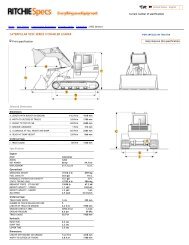
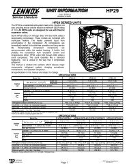
REQUIRED CLEARANCE TO COMBUSTIBLE MATL.<br />
(Refer to Maximum <strong>Operating</strong> Clearances)<br />
INCHES [mm]<br />
TOP OF UNIT...................................................................................14.00 [355.6]<br />
DUCT SIDE OF UNIT.........................................................................2.00 [50.8]<br />
SIDE OPPOSITE DUCTS ................................................................14.00 [355.6]<br />
BOTTOM OF UNIT .............................................................................0.50 [12.7]<br />
NEC. REQUIRED CLEARANCES.<br />
INCHES [mm]<br />
BETWEEN UNITS, POWER ENTRY SIDE ....................................42.00 [1066.8]<br />
UNIT AND UNGROUNDED SURFACES, POWER ENTRY SIDE .36.00 [914.0]<br />
UNIT AND BLOCK OR CONCRETE WALLS AND OTHER<br />
GROUNDED SURFACES, POWER ENTRY SIDE.........................42.00 [1066.8]<br />
UNIT WEIGHT<br />
UNIT HEIGHT<br />
CENTER OF GRAVITY<br />
UNIT ELECTRICAL CHARACTERISTICS<br />
IN. (MM)<br />
IN. (MM)<br />
lb. kg ”A”<br />
X Y Z<br />
50SD024 208/230-1-60 343 156 39.02 (991) 20.0 (508) 19.3 (490) 17.6 (447)<br />
50SD030 208/230-1-60 366 166 41.02 (1042) 20.0 (508) 14.0 (356) 13.0 (330)<br />
Fig. 2—50SD024-030 Unit Dimensions<br />
3<br />
REQUIRED CLEARANCE FOR OPERATION AND SERVICING<br />
INCHES [mm]<br />
EVAP. COIL ACCESS SIDE............................................................36.00 [914.0]<br />
POWER ENTRY SIDE....................................................................42.00 [1066.8]<br />
(EXCEPT FOR NEC REQUIREMENTS)<br />
UNIT TOP .......................................................................................48.00 [1219.2]<br />
SIDE OPPOSITE DUCTS ..............................................................36.00 [914.0]<br />
DUCT PANEL .................................................................................12.00 [304.8] *<br />
*MINIMUM DISTANCES: IF UNIT IS PLACED LESS THAN 304.8 [12.00] FROM<br />
WALL SYSTEM, THEN SYSTEM PERFORMANCE MAYBE COMPROMISE.<br />
C99007
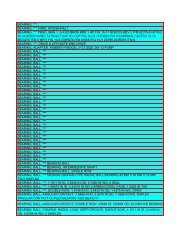
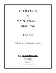
REQUIRED CLEARANCE TO COMBUSTIBLE MATL.<br />
(Refer to Maximum <strong>Operating</strong> Clearances)<br />
INCHES [mm]<br />
TOP OF UNIT...................................................................................14.00 [355.6]<br />
DUCT SIDE OF UNIT.........................................................................2.00 [50.8]<br />
SIDE OPPOSITE DUCTS ................................................................14.00 [355.6]<br />
BOTTOM OF UNIT .............................................................................0.50 [12.7]<br />
NEC. REQUIRED CLEARANCES.<br />
INCHES [mm]<br />
BETWEEN UNITS, POWER ENTRY SIDE ....................................42.00 [1066.8]<br />
UNIT AND UNGROUNDED SURFACES, POWER ENTRY SIDE .36.00 [914.0]<br />
UNIT AND BLOCK OR CONCRETE WALLS AND OTHER<br />
GROUNDED SURFACES, POWER ENTRY SIDE.........................42.00 [1066.8]<br />
REQUIRED CLEARANCE FOR OPERATION AND SERVICING<br />
INCHES [mm]<br />
EVAP. COIL ACCESS SIDE............................................................36.00 [914.0]<br />
POWER ENTRY SIDE....................................................................42.00 [1066.8]<br />
(EXCEPT FOR NEC REQUIREMENTS)<br />
UNIT TOP .......................................................................................48.00 [1219.2]<br />
SIDE OPPOSITE DUCTS ..............................................................36.00 [914.0]<br />
DUCT PANEL .................................................................................12.00 [304.8] *<br />
*MINIMUM DISTANCES: IF UNIT IS PLACED LESS THAN 304.8 [12.00] FROM<br />
WALL SYSTEM, THEN SYSTEM PERFORMANCE MAYBE COMPROMISE.<br />
UNIT WEIGHT<br />
UNIT HEIGHT<br />
CENTER OF GRAVITY<br />
UNIT ELECTRICAL CHARACTERISTICS<br />
IN. (MM)<br />
IN. (MM)<br />
lb. kg ”A”<br />
X Y Z<br />
50SD036 208/230-1-60 433 196 42.98 (1092) 21.0 (533) 20.5 (520) 16.6 (422)<br />
50SD042 208/230-1-60 460 209 46.98 (1193) 21.0 (533) 20.5 (520) 17.1 (434)<br />
50SD048 208/230-1-60 480 218 46.98 (1193) 21.0 (533) 20.0 (508) 17.4 (442)<br />
50SD060 208/230-1-60 492 223 46.98 (1193) 21.0 (533) 20.0 (508) 17.6 (447)<br />
Fig. 3—50SD036–060 Unit Dimensions<br />
A05126<br />
UNIT FALLING HAZARD<br />
Failure to follow this warnig could result to personal injury or<br />
death. Never st<strong>and</strong> beneath rigged units or lift over people.<br />
Never exceed 200 lbs. per bracket lifting force.<br />
4<br />
UNIT FALLING HAZARD<br />
Failure to follow this warning could result to personal injury<br />
or death.<br />
Accessory lifting kit is only to be used with Small Packaged<br />
units which have a composite base pan with molded rigging<br />
holds.<br />
INSPECTION<br />
Prior to initial use, <strong>and</strong> at monthly intervals, all rigging brackets<br />
<strong>and</strong> straps should be visually inspected for any damage, evidence
HVAC unit<br />
base<br />
Screw<br />
(NO TE A)<br />
Gasketing<br />
inner flange*<br />
Screw<br />
(NOTE A)<br />
HVAC unit<br />
base<br />
Gask eting<br />
inner flange*<br />
*Gasketing<br />
outer flange<br />
*Gasketing<br />
outer flange<br />
Flashing field<br />
supplied<br />
Wood nailer*<br />
Roofcurb*<br />
Flashing field<br />
supplied<br />
Wood nailer*<br />
Roofcurb*<br />
Roofing material<br />
field supplied<br />
Insulation (field<br />
supplied)<br />
Roofing material<br />
field supplied<br />
Insulation (field<br />
supplied)<br />
Cant strip<br />
field supplied<br />
Duct wo rk<br />
field supplied<br />
Cant strip<br />
field supplied<br />
Duct wo rk<br />
field supplied<br />
Roof<br />
Roof<br />
*Provided with roofcurb<br />
*Provided with roofcurb<br />
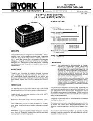
Roof Curb for Small Cabinet<br />
Note A: When unit mounting scre w is used ,<br />
retainer bracke t must also be used.<br />
Roof Curb for Large Cabinet<br />
Note A: When unit mounting scre w is used ,<br />
retainer bracket must also be used.<br />
G<br />
F<br />
B Typ.<br />
Supply opening<br />
(B x C)<br />
D<br />
C Typ.<br />
E<br />
G<br />
F<br />
R/A<br />
S/A<br />
A<br />
E<br />
D<br />
Gasket around<br />
duct<br />
Insulated<br />
deck pan<br />
Long<br />
Support<br />
Short<br />
Support<br />
Insulated<br />
deck pan<br />
Gasket around<br />
outer edge<br />
Return opening<br />
(B X C)<br />
UNIT SIZE<br />
ODS CATALOG<br />
NUMBER<br />
A<br />
IN. (MM)<br />
B<br />
IN. (MM)<br />
C<br />
IN. (MM)<br />
D<br />
IN. (MM)<br />
E<br />
IN. (MM)<br />
F<br />
IN. (MM)<br />
G<br />
IN. (MM)<br />
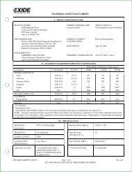
CPRFCURB006A00 8 (203) 11(279) 16-1/2 (419) 28-3/4 (730) 30-3/8 (771) 44-5/16 (1126) 45-15/16 (1167)<br />
50SD024-030<br />
CPRFCURB007A00 14 (356) 11(279) 16-1/2 (419) 28-3/4 (730) 30-3/8 (771) 44-5/16 (1126) 45-15/16 (1167)<br />
CPRFCURB008A00 8 (203) 16-3/16 (411) 17-3/8 (441) 40-5/16 (1022) 41-15/16 (1065) 44-7/16 (1129) 46-1/16 (1169)<br />
50SD036-060<br />
CPRFCURB009A00 14 (356) 16-3/16 (411) 17-3/8 (441) 40-5/16 (1022) 41-15/16 (1065) 44-7/16 (1129) 46-1/16 (1169)<br />
NOTES:<br />
1. Dimensions in ( ) are in millimeters.<br />
2. Roof curb is made of 16-gage steel.<br />
3. Table lists only the dimensions per part number that have changed<br />
4. Insulated panels: 1-in. thick fiberglass 1 lb. density.<br />
Fig. 4A—Roof Curb Dimensions<br />
A05165<br />
of wear, structural deformation, or cracks. Particular attention<br />
should be paid to excessive wear at hoist hooking points <strong>and</strong> load<br />
support areas. Brackets or straps showing any kind of wear in these<br />
areas must not be used <strong>and</strong> should be discarded.<br />
INSTALLATION<br />
1. Position the lifting bracket assembly around the base of the<br />
unit. Leave the top shipping skid on the unit to act as a<br />
spreader bar. Be sure the strap does not twist.<br />
5<br />
2. Place each of the four (4) metal lifting brackets into the<br />
rigging holds in the composite pan.<br />
3. Tighten the ratchet strap unit tight. Lifting brackets should be<br />
secure in the rigging holds.<br />
4. Attach the clevis or hook of sufficient strength to hole in the<br />
lifting bracket (See Fig. 6).
1 2<br />
y<br />
4 3<br />
x<br />
C00071<br />
CORNER #<br />
50SD<br />
024 030 036 042 048 060<br />
1 69 74 87 93 97 99<br />
2 53 57 68 72 74 76<br />
3 83 88 104 111 116 119<br />
4 138 147 174 184 193 198<br />
TOTAL WEIGHT 343 366 433 460 480 492<br />
Fig. 4B—50SD Unit Corner Weights (in Pounds)<br />
A<br />
B<br />
C<br />
MAXIMUM ALLOWABLE<br />
DIFFERENCE (in.)<br />
A-B B-C A-C<br />
1/4 1/4 1/4<br />
C99065<br />
Fig. 5A—Unit Leveling Tolerances<br />
5. Attach safety straps directly to the field supplied rigging straps<br />
or clevis clip. Do not attach the safety straps to the lifting<br />
brackets.<br />
6. Use the top of the unit as a spreader bar to prevent the rigging<br />
straps from damaging the unit. If the wood top is not available,<br />
use a spreader bar of sufficient length to not damage the unit.<br />
UNIT FALLING HAZARD<br />
Failure to follow this warning could result to personal injury<br />
or death.<br />
Lifting point should be directly over the center of gravity for<br />
the unit.<br />
Step 6—Connect Condensate Drain<br />
NOTE: When installing condensate drain connection be sure to<br />
comply with local codes <strong>and</strong> restrictions.<br />
Model 50SD disposes of condensate water through a 3/4 in. NPT<br />
fitting which exits through the base on the evaporator coil access<br />
side. See Fig. 2 & 3 for location.<br />
Condensate water can be drained directly onto the roof in rooftop<br />
installations (where permitted) or onto a gravel apron in groundlevel<br />
installations. Install a field-supplied condensate trap at end of<br />
6<br />
condensate connection to ensure proper drainage. Make sure that<br />
the outlet of the trap is at least 1 in. lower than the drainpan<br />
condensate connection to prevent the pan from overflowing (See<br />
Fig. 7). When using a gravel apron, make sure it slopes away from<br />
the unit.<br />
Connect a drain tube using a minimum of 3/4 -in. PVC or 3/4 -in.<br />
copper pipe (all field-supplied) at the outlet end of the 2-in. trap.<br />
Do not undersize the tube. Pitch the drain tube downward at a<br />
slope of at least 1-in. for every 10 ft. of horizontal run. Be sure to<br />
check the drain tube for leaks. Prime trap at the beginning of the<br />
cooling season start-up.<br />
Step 7—Install Duct Connections<br />
The unit has duct flanges on the supply- <strong>and</strong> return-air openings on<br />
the side <strong>and</strong> bottom of the unit. For downshot applications the<br />
ductwork can be connected to the roof curb. See Fig. 2&3for<br />
connection sizes <strong>and</strong> locations.<br />
IMPORTANT: Use flexible connectors between ductwork <strong>and</strong><br />
unit to prevent transmission of vibration. Use suitable gaskets to<br />
ensure weathertight <strong>and</strong> airtight seal. When electric heat is<br />
installed, use fire proof canvas (or similar heat resistant material)<br />
connector between ductwork <strong>and</strong> unit discharge connection. If<br />
flexible duct is used, insert a sheet metal sleeve inside duct. Heat
OPTIONAL<br />
RETURN<br />
AIR<br />
OPENING<br />
OPTIONAL<br />
SUPPLY<br />
AIR<br />
OPENING<br />
2"<br />
EVAP. COIL<br />
COND. COIL<br />
Fig. 5B—Slab Mounting Detail<br />
C99096<br />
DETAIL A<br />
SIZE<br />
MAXIMUM WEIGHT A B<br />
lb. kg in. mm. in. mm.<br />
UNIT 50SD<br />
024 372 169 20.0 508.0 19.3 490.2<br />
030 395 179 20.0 508.0 14.0 355.6<br />
036 462 210 21.0 533.4 20.5 520.7<br />
042 489 222 21.0 533.4 20.5 520.7<br />
048 509 231 21.0 533.4 20.0 508.0<br />
060 521 236 21.0 533.4 20.0 508.0<br />
Fig. 6—Suggested Rigging<br />
C99066<br />
resistant duct connector (or sheet metal sleeve) must extend 24-in.<br />
from the unit discharge connection flange into the ductwork.<br />
CONFIGURING UNITS FOR DOWNFLOW (VERTICAL) DIS-<br />
CHARGE<br />
ELECTRICAL SHOCK HAZARD<br />
Failure to follow this warning could result in personal injury<br />
or death.<br />
Before performing service or maintenance operations on the<br />
system, turn off main power to unit <strong>and</strong> install lockout tag.<br />
1. Open all electrical disconnects <strong>and</strong> install lockout tag before<br />
starting any service work.<br />
7<br />
2. Remove return duct cover located on duct panel by breaking<br />
four (4) connecting tabs with screwdriver <strong>and</strong> a hammer. (Fig.<br />
8&9)<br />
3. To remove supply duct cover, break front <strong>and</strong> right side<br />
connecting tabs with a screwdriver <strong>and</strong> a hammer. Push louver<br />
down to break rear <strong>and</strong> left side tabs. (Fig. 8 & 9)<br />
4. If unit ductwork is to be attached to vertical opening flanges<br />
on the unit composite base (jackst<strong>and</strong> applications only), do so<br />
at this time. Collect ALL screws that were removed. Do not<br />
leave screws on rooftop as permanent damage to the roof may<br />
occur.<br />
5. It is recommended that the unit base insulation around the<br />
perimeter of the vertical return-air opening be secured to the<br />
unit base with aluminum tape. Applicable local codes may
Table 1—Physical Data—Unit 50SD<br />
UNIT SIZE 024 030 036 042 048 060<br />
NOMINAL CAPACITY (ton) 2 2-1/2 3 3-1/2 4 5<br />
OPERATING WEIGHT (lb.) 343 366 433 460 480 492<br />
COMPRESSOR<br />
Scroll<br />
REFRIGERANT (R-22)<br />
Quantity (lb.)<br />
7.8 8.4 10.9 10.9 12.3 12.0<br />
REFRIGERANT METERING DEVICE<br />
Orifice ID (in.)<br />
CONDENSER COIL<br />
Rows...Fins/in.<br />
Face Area (sq. ft.)<br />
CONDENSER FAN<br />
Nominal Cfm<br />
Diameter (in.)<br />
Motor Hp (Rpm)<br />
EVAPORATOR COIL<br />
Rows...Fins/in.<br />
Face Area (sq. ft.)<br />
EVAPORATOR BLOWER<br />
Nominal Airflow (Cfm)<br />
Size (in.)<br />
Motor Hp (RPM)<br />
RETURN-AIR FILTERS (in.)*<br />
Throwaway<br />
Accurater<br />
0.065 0.070 0.080 0.088 0.088 0.101<br />
2...21<br />
11.9<br />
2700<br />
22<br />
1/8 (825)<br />
3...17<br />
3.7<br />
800<br />
10x10<br />
1/3 (1050)<br />
2...21<br />
13.6<br />
2700<br />
22<br />
1/8 (825)<br />
3...17<br />
3.7<br />
1000<br />
10x10<br />
1/3 (1050)<br />
2...21<br />
15.5<br />
2800<br />
22<br />
1/8 (825)<br />
3...17<br />
4.7<br />
1200<br />
11x10<br />
1/2 (1000)<br />
2...21<br />
19.4<br />
2800<br />
22<br />
1/8 (825)<br />
3...17<br />
4.7<br />
1400<br />
11x10<br />
1/2 (1075)<br />
2...21<br />
19.4<br />
3300<br />
22<br />
1/4 (1100)<br />
3...17<br />
5.6<br />
1600<br />
11x10<br />
1/2 (1075)<br />
2...21<br />
19.4<br />
3300<br />
22<br />
1/4 (1100)<br />
4...17<br />
5.6<br />
1750<br />
11x10<br />
1.0 (1040)<br />
20x24x1 20x24x1 24x36x1 24x36x1 24x36x1 24x36x1<br />
* Required filter sizes shown are based on the larger of the ARI (Air Conditioning <strong>and</strong> Refrigeration Institute) rated cooling airflow or the heating airflow velocity of 300<br />
ft./min. for throwaway type. For permanent filters, follow filter manufacturer’s recommendations for filter size based on allowable face velocity. Air filter pressure drop for<br />
non-st<strong>and</strong>ard filters must not exceed 0.08 in. wg.<br />
1” (25mm) MIN.<br />
12. Size all ductwork for maximum required airflow (either<br />
TRAP<br />
heating or cooling) for unit being installed. Avoid abrupt duct<br />
OUTLET<br />
size increases or decreases or performance may be affected.<br />
13. Adequately insulate <strong>and</strong> weatherproof all ductwork located<br />
2” (50mm) MIN. outdoors. Insulate ducts passing through unconditioned space,<br />
<strong>and</strong> use vapor barrier in accordance with latest issue of Sheet<br />
Metal <strong>and</strong> Air Conditioning Contractors National Association<br />
C99013<br />
(SMACNA) <strong>and</strong> Air Conditioning Contractors of America<br />
Fig. 7—Condensate Trap<br />
(ACCA) minimum installation st<strong>and</strong>ards for heating <strong>and</strong> air<br />
conditioning systems. Secure all ducts to building structure.<br />
require aluminum tape to prevent exposed fiberglass.<br />
14. Flash, weatherproof, <strong>and</strong> vibration-isolate all openings in<br />
6. Cover both horizontal duct openings with the duct covers from<br />
building structure in accordance with local codes <strong>and</strong> good<br />
the accessory duct cover kit. Ensure opening is air-<strong>and</strong><br />
building practices.<br />
watertight.<br />
7. After completing unit conversion, perform all safety checks<br />
<strong>and</strong> power up unit.<br />
NOTE: The design <strong>and</strong> installation of the duct system must be in<br />
accordance with the st<strong>and</strong>ards of the NFPA for installation of<br />
nonresidence-type air conditioning <strong>and</strong> ventilating systems, NFPA<br />
90A or residence-type, NFPA 90B; <strong>and</strong>/or local codes <strong>and</strong><br />
ordinances.<br />
Adhere to the following criteria when selecting, sizing, <strong>and</strong><br />
installing the duct system:<br />
8. Units are shipped for side shot installation.<br />
9. Select <strong>and</strong> size ductwork, supply-air registers, <strong>and</strong> return-air<br />
grilles according to American Society of Heating, Refrigeration<br />
<strong>and</strong> Air Conditioning Engineers (ASHRAE) recommendations.<br />
10. Use flexible transition between rigid ductwork <strong>and</strong> unit to<br />
prevent transmission of vibration. The transition may be<br />
screwed or bolted to duct flanges. Use suitable gaskets to<br />
SUPPLY<br />
RETURN<br />
ensure weathertight <strong>and</strong> airtight seal.<br />
DUCT<br />
DUCT<br />
OPENING<br />
OPENING<br />
11. All units must have field-supplied filters or accessory filter<br />
C99011<br />
rack installed in the return-air side of the unit. Recommended<br />
Fig. 8—Supply <strong>and</strong> Return Duct Opening<br />
sizes for filters are shown in Table 1.<br />
8
Table 2—Minimum Airflow for Safe Electric Heater<br />
Operation (Cfm)<br />
SIZE 024 030 036 042 048 060<br />
Cfm 800 1000 1200 1400 1600 1750<br />
DUCT COVERS REMOVED<br />
Fig. 9—Vertical Duct Cover Removed<br />
Step 8—Install Electrical Connection<br />
C99012<br />
ELECTRICAL SHOCK HAZARD<br />
Failure to follow this warning could result in personal injury<br />
or death.<br />
The unit cabinet must have an uninterrupted, unbroken<br />
electrical ground to minimize the possibility of personal<br />
injury if an electrical fault should occur. This ground may<br />
consist of an electrical wire connected to the unit ground<br />
screw in the control compartment, or conduit approved for<br />
electrical ground when installed in accordance with NEC<br />
(National Electrical Code) ANSI/NFPA (latest edition) <strong>and</strong><br />
local electrical codes. In Canada, follow Canadian Electrical<br />
Code CSA (Canadian St<strong>and</strong>ards Association) C22.1 <strong>and</strong> local<br />
electrical codes.<br />
INSTALLATION REQUIREMENTS<br />
Failure to follow these precautions may result in damage to<br />
the unit being installed:<br />
1. Make all electrical connections in accordance with NEC<br />
ANSI/NFPA (latest edition) <strong>and</strong> local electrical codes<br />
governing such wiring. In Canada, all electrical connections<br />
must be in accordance with CSA st<strong>and</strong>ard C22.1<br />
Canadian Electrical Code Part 1 <strong>and</strong> applicable local<br />
codes. Refer to unit wiring diagram.<br />
2. Use only copper conductor for connections between<br />
field-supplied electrical disconnect switch <strong>and</strong> unit. DO<br />
NOT USE ALUMINUM WIRE.<br />
3. Be sure that high-voltage power to unit is within operating<br />
voltage range indicated on unit rating plate.<br />
4. Do not damage internal components when drilling through<br />
any panel to mount electrical hardware, conduit, etc.<br />
Consult local power company for correction of improper<br />
voltage.<br />
HIGH-VOLTAGE CONNECTIONS<br />
The unit must have a separate electrical service with a fieldsupplied,<br />
waterproof, disconnect switch mounted at, or within<br />
sight from, the unit. Refer to the unit rating plate for maximum<br />
fuse/circuit breaker size <strong>and</strong> minimum circuit amps (ampacity) for<br />
wire sizing. See Table 3 for electrical data.<br />
The field-supplied disconnect switch box may be mounted on the<br />
unit over the high-voltage inlet hole when the st<strong>and</strong>ard power <strong>and</strong><br />
low-voltage entry points are used. See Fig. 2 & 3 for acceptable<br />
location.<br />
See unit wiring label <strong>and</strong> Fig. 10 for reference when making high<br />
voltage connections. Proceed as follows to complete the highvoltage<br />
connections to the unit.<br />
Single phase units:<br />
1. Run the high-voltage (L1, L2) <strong>and</strong> ground leads into the<br />
control box.<br />
2. Connect ground lead to chassis ground connection.<br />
3. Connect L1 to pressure lug connection 11 of the compressor<br />
contactor.<br />
4. Connect L2 to pressure lug connection 23 of the compressor<br />
contactor.<br />
SPECIAL PROCEDURES FOR 208-V OPERATION<br />
ELECTRICAL SHOCK HAZARD<br />
Failure to follow this warning could result in personal injury<br />
or death.<br />
Make sure that the power supply to the unit is switched OFF<br />
<strong>and</strong> lockout tag installed before making any wiring changes.<br />
9<br />
CONTROL VOLTAGE CONNECTIONS<br />
NOTE: Do not use any type of power-stealing thermostat. Unit<br />
control problems may result.<br />
Use no. 18 American Wire Gage (AWG) color-coded, insulated<br />
(35 C minimum) wires to make the control voltage connections
UNIT<br />
SIZE<br />
V-PH-HZ<br />
VOLTAGE<br />
RANGE<br />
Table 3—Electrical Data—50SD<br />
COMPRESSOR OFM IFM<br />
ELECTRIC HEAT<br />
(SINGLE POINT CONNECTION)<br />
Min Max RLA LRA FLA FLA Nominal Kw * FLA MCA<br />
024 208/230–1–60 187 253 10.9 54.0 0.9 2.0<br />
030 208/230–1–60 187 253 14.0 72.5 0.9 2.0<br />
036 208/230–1–60 187 253 16.0 88.0 0.9 3.1<br />
042 208/230–1–60 187 253 18.4 104.0 0.9 4.1<br />
048 208/230–1–60 187 253 18.3 109.0 1.5 4.1<br />
060 208/230–1–60 187 253 25.0 148.0 1.5 6.2<br />
(See legend following Electrical Data charts)<br />
-/-<br />
3.8/5.0<br />
7.5/10.0<br />
5.4/7.2<br />
-/-<br />
3.8/5.0<br />
7.5/10.0<br />
11.3/15.0<br />
5.4/7.2<br />
-/-<br />
3.8/5.0<br />
7.5/10.0<br />
11.3/15.0<br />
5.4/7.2<br />
-/-<br />
3.8/5.0<br />
7.5/10.0<br />
11.3/15.0<br />
15.0/20.0<br />
5.4/7.2<br />
-/-<br />
3.8/5.0<br />
7.5/10.0<br />
11.3/15.0<br />
15.0/20.0<br />
5.4/7.2<br />
-/-<br />
3.8/5.0<br />
7.5/10.0<br />
11.3/15.0<br />
15.0/20.0<br />
5.4/7.2<br />
-/-<br />
18.1/20.8<br />
36.1/41.7<br />
26.0/30.0<br />
-/-<br />
18.1/20.8<br />
36.1/41.7<br />
54.2/62.5<br />
26.0/30.0<br />
-/-<br />
18.1/20.8<br />
36.1/41.7<br />
54.2/62.5<br />
26.0/30.0<br />
-/-<br />
18.1/20.8<br />
36.1/41.7<br />
54.2/62.5<br />
72.2/83.3<br />
26.0/30.0<br />
-/-<br />
18.1/20.8<br />
36.1/41.7<br />
54.2/62.5<br />
72.2/83.3<br />
26.0/30.0<br />
-/-<br />
18.1/20.8<br />
36.1/41.7<br />
54.2/62.5<br />
72.2/83.3<br />
26.0/30.0<br />
16.5/16.5<br />
25.1/28.5<br />
47.6/54.6<br />
35.0/40.0<br />
20.4/20.4<br />
25.1/28.5<br />
47.6/54.6<br />
70.2/80.6<br />
35.0/40.0<br />
24.0/24.0<br />
26.4/29.9<br />
49.0/56.0<br />
71.6/82.0<br />
36.4/41.4<br />
28.0/28.0<br />
28.0/31.2<br />
50.3/57.2<br />
72.8/83.3<br />
95.4/109.3<br />
37.6/42.6<br />
28.5/28.5<br />
28.5/31.2<br />
50.3/57.2<br />
72.8/83.3<br />
95.4/109.3<br />
37.6/42.6<br />
39.0/39.0<br />
39.0/39.0<br />
52.9/59.8<br />
75.4/85.9<br />
98.0/111.9<br />
40.2/45.3<br />
POWER SUPPLY<br />
Max Fuse<br />
or<br />
Ckt Bkr<br />
20/20<br />
30/30<br />
50/60<br />
35/40<br />
25/25<br />
25/30<br />
50/60<br />
—<br />
35/40<br />
30/30<br />
30/30<br />
50/60<br />
—<br />
40/45<br />
35/35<br />
35/35<br />
60/60<br />
—<br />
—<br />
40/45<br />
35/35<br />
35/35<br />
60/60<br />
—<br />
—<br />
40/45<br />
50/50<br />
50/50<br />
60/60<br />
—<br />
—<br />
50/50<br />
MOCP<br />
—<br />
—<br />
—<br />
—<br />
—<br />
—<br />
—<br />
80/90<br />
—<br />
—<br />
—<br />
—<br />
80/90<br />
—<br />
—<br />
—<br />
—<br />
80/90<br />
100/110<br />
—<br />
—<br />
—<br />
—<br />
80/90<br />
100/110<br />
—<br />
—<br />
—<br />
—<br />
80/90<br />
100/125<br />
—<br />
LEGEND<br />
FLA — Full Load Amps<br />
LRA — Locked Rotor Amps<br />
MCA — Minimum Circuit Amps<br />
MOCP — Maximum Overcurrent Protection<br />
RLA — Rated Load Amps<br />
NOTES:<br />
1. In compliance with NEC (National Electrical Code) requirements<br />
for multimotor <strong>and</strong> combination load equipment (refer to NEC<br />
Articles 430 <strong>and</strong> 440), the overcurrent protective device for the<br />
unit shall be Power Supply fuse . The CGA (Canadian Gas<br />
Association) units may be fuse or circuit breaker.<br />
2. Minimum wire size is based on 60 C copper wire. If other than<br />
60 C wire is used, or if length exceeds wire length in table,<br />
determine size from NEC.<br />
®<br />
HIGH VOLTAGE<br />
POWER LEADS<br />
(SEE UNIT WIRING<br />
LABEL)<br />
CONTROL BOX<br />
GND<br />
FIELD-SUPPLIED<br />
FUSED DISCONNECT<br />
POWER<br />
SUPPLY<br />
A05108<br />
LOW-VOLTAGE<br />
POWER LEADS<br />
(SEE UNIT<br />
WIRING LABEL)<br />
YEL(Y)<br />
GRN(G)<br />
RED(R)<br />
BRN(C)<br />
Y<br />
G<br />
R<br />
C<br />
THERMOSTAT<br />
(TYPICAL)<br />
SPLICE BOX<br />
LEGEND<br />
Field Control-Voltage Wiring<br />
Field High-Voltage Wiring<br />
NOTE: Use blue wire for 3-phase units only.<br />
C99010<br />
Fig. 10—High- <strong>and</strong> Control-Voltage Connections<br />
10
etween the thermostat <strong>and</strong> the unit. If the thermostat is located<br />
more than 100 ft. from the unit (as measured along the control<br />
voltage wires), use no. 16 AWG color-coded, insulated (35 C<br />
minimum) wires.<br />
STANDARD CONNECTION<br />
Remove knockout hole located in the electric heat panel adjacent<br />
to the control access panel. See Fig. 2&3.Removetherubber<br />
grommet from the installer’s packet (included with unit) <strong>and</strong> install<br />
grommet in the knockout opening. Provide a drip loop before<br />
running wire through panel.<br />
Run the low-voltage leads from the thermostat, through the inlet<br />
hole, <strong>and</strong> into unit low-voltage splice box.<br />
Locate five 18-gage wires leaving control box. These low-voltage<br />
connection leads can be identified by the colors red, green, yellow,<br />
brown, <strong>and</strong> white (See Fig. 10). Ensure the leads are long enough<br />
to be routed into the low-voltage splice box (located below right<br />
side of control box). Stripped yellow wire is located in connection<br />
box. Route leads through hole in bottom of control box <strong>and</strong> make<br />
low-voltage connections (See Fig. 10). Secure all cut wires, so that<br />
they do not interfere with operation of unit.<br />
TRANSFORMER PROTECTION<br />
The transformer is of the energy-limiting type. It is set to<br />
withst<strong>and</strong> a 30-second overload or shorted secondary condition.<br />
PRE-START-UP<br />
FIRE, EXPLOSION, ELECTRICAL SHOCK HAZARD<br />
Failure to observe the following warnings could result in<br />
serious personal injury:<br />
1. Follow recognized safety practices <strong>and</strong> wear protective<br />
goggles when checking or servicing refrigerant system.<br />
2. Relieve <strong>and</strong> recover all refrigerant from system before<br />
touching or disturbing anything inside terminal box if<br />
refrigerant leak is suspected around compressor terminals.<br />
3. Never attempt to repair soldered connection while refrigerant<br />
system is under pressure.<br />
4. Do not use torch to remove any component. System<br />
contains oil <strong>and</strong> refrigerant under pressure. To remove a<br />
component, wear protective goggles <strong>and</strong> proceed as follows:<br />
a. Shut off electrical power to unit.<br />
b. Relieve <strong>and</strong> reclaim all refrigerant from system using<br />
both high- <strong>and</strong> low-pressure ports.<br />
c. Cut component connecting tubing with tubing cutter <strong>and</strong><br />
remove component from unit.<br />
d. Carefully unsweat remaining tubing stubs when necessary.<br />
Oil can ignite when exposed to torch flame.<br />
Proceed as follows to inspect <strong>and</strong> prepare the unit for initial<br />
startup:<br />
1. Remove access panel.<br />
2. Read <strong>and</strong> follow instructions on all WARNING, CAUTION,<br />
<strong>and</strong> INFORMATION labels attached to, or shipped with, unit.<br />
3. Make the following inspections:<br />
a. Inspect for shipping <strong>and</strong> h<strong>and</strong>ling damages such as broken<br />
lines, loose parts, disconnected wires, etc.<br />
b. Inspect for oil at all refrigerant tubing connections <strong>and</strong> on<br />
unit base. Detecting oil generally indicates a refrigerant<br />
leak. Leak test all refrigerant tubing connections using<br />
electronic leak detector, halide torch, or liquid-soap solution.<br />
If a refrigerant leak is detected, see Check for<br />
Refrigerant Leaks section.<br />
11<br />
c. Inspect all field- <strong>and</strong> factory-wiring connections. Be sure<br />
that connections are completed <strong>and</strong> tight.<br />
d. Ensure electrical wiring does not contact refrigerant tubes<br />
or sharp metal edges.<br />
e. Inspect coil fins. If damaged during shipping <strong>and</strong> h<strong>and</strong>ling,<br />
carefully straighten fins with a fin comb.<br />
Verify the following conditions:<br />
a. Make sure that condenser-fan blade is correctly positioned<br />
in fan orifice. Leading edge of condenser-fan blade should<br />
be 1/2 in. maximum from fan orifice (See Fig. 11).<br />
MOTOR<br />
1/8" MAX BETWEEN<br />
MOTOR AND FAN HUB<br />
MOTOR SHAFT<br />
Fig. 11—Fan Blade Clearance<br />
FAN GRILLE<br />
C99009<br />
b. Make sure that air filter(s) is in place.<br />
c. Make sure that condensate drain trap is filled with water to<br />
ensure proper drainage.<br />
d. Make sure that all tools <strong>and</strong> miscellaneous loose parts have<br />
been removed.<br />
START-UP<br />
CHECK FOR REFRIGERANT LEAKS<br />
Proceed as follows to locate <strong>and</strong> repair a refrigerant leak <strong>and</strong> to<br />
charge the unit:<br />
1. Locate leak <strong>and</strong> make sure that refrigerant system pressure has<br />
been relieved <strong>and</strong> reclaimed from both high- <strong>and</strong> low-pressure<br />
ports.<br />
2. Repair leak following accepted practices. NOTE: Install a<br />
filter drier whenever the system has been opened for repair.<br />
3. Add a small charge of R-22 refrigerant vapor to system <strong>and</strong><br />
leak-test unit.<br />
4. Recover refrigerant from refrigerant system <strong>and</strong> evacuate to<br />
500 microns if no additional leaks are not found.<br />
5. Charge unit with R-22 refrigerant, using a volumetriccharging<br />
cylinder or accurate scale. Refer to unit rating plate<br />
for required charge. Be sure to add extra refrigerant to<br />
compensate for internal volume of filter drier.<br />
START UP COOLING SECTION AND MAKE ADJUST-<br />
MENTS<br />
EQUIPMENT DAMAGE HAZARD<br />
Failure to follow this caution may result in unit component<br />
damage.<br />
Complete the required procedures given in the Pre-<strong>Start</strong>- <strong>Up</strong><br />
section before starting the unit. Do not jumper any safety<br />
devices when operating the unit. Do not operate the compressor<br />
when the outdoor temperature is below 40°F (unless<br />
accessory low-ambient kit is installed). Do not rapid-cycle the<br />
compressor. Allow 5 minutes between “on” cycles to prevent<br />
compressor damage.<br />
CHECKING COOLING CONTROL OPERATION<br />
<strong>Start</strong> <strong>and</strong> check the unit for proper cooling control operation as<br />
follows:<br />
1/2˝
A05112<br />
Fig. 12—Wiring Diagram (208/230-60-1)<br />
12
1. Place room thermostat SYSTEM switch in OFF position.<br />
Observe that blower motor starts when FAN switch is placed<br />
in ON position <strong>and</strong> shuts down after 30 second fan time delay<br />
expires when FAN switch is placed in AUTO position.<br />
2. Place SYSTEM switch in COOL position <strong>and</strong> FAN switch in<br />
AUTO position. Set cooling control below room temperature.<br />
Observe that compressor, condenser fan, <strong>and</strong> evaporator<br />
blower motors start. Observe that compressor <strong>and</strong> outdoor fan<br />
shut down when control setting is satisfied <strong>and</strong> that indoor<br />
blower shuts down after 30 second fan time delay expires.<br />
3. When using an auto-changeover room thermostat, place both<br />
SYSTEM <strong>and</strong> FAN switches in AUTO positions. Observe that<br />
unit operates in heating mode when temperature control is set<br />
to “call for heating” (above room temperature) <strong>and</strong> operates in<br />
cooling mode when temperature control is set to “call for<br />
cooling” (below room temperature).<br />
IMPORTANT:<br />
CHECKING AND ADJUSTING REFRIGERANT CHARGE<br />
The refrigerant system is fully charged with R-22 refrigerant,<br />
tested, <strong>and</strong> factory-sealed.<br />
NOTE: Adjustment of the refrigerant charge is not required<br />
unless the unit is suspected of not having the proper R-22 charge.<br />
A superheat charging chart is attached to the outside of the service<br />
access panel. The chart includes the required suction line temperature<br />
at given suction line pressures <strong>and</strong> outdoor ambient temperatures<br />
(See Fig. 13).<br />
An accurate superheat, thermocouple- or thermistor-type thermometer,<br />
<strong>and</strong> a gauge manifold are required when using the<br />
superheat charging method for evaluating the unit charge. Do not<br />
use mercury or small dial-type thermometers because they are not<br />
adequate for this type of measurement.<br />
NOTE: Allow system to operate in the cooling mode for a<br />
minimum of 10 minutes before checking or adjusting refrigerant<br />
charge.<br />
EQUIPMENT DAMAGE HAZARD<br />
Failure to follow this caution may result in unit component<br />
damage.<br />
When evaluating the refrigerant charge, an indicated adjustment<br />
to the specified factory charge must always be very<br />
minimal. If a substantial adjustment is indicated, an abnormal<br />
condition exists somewhere in the cooling system, such as<br />
insufficient airflow across either coil or both coils.<br />
Proceed as follows:<br />
1. Remove caps from low- <strong>and</strong> high-pressure service fittings.<br />
2. Using hoses with valve core depressors, attach low- <strong>and</strong><br />
high-pressure gauge hoses to low- <strong>and</strong> high-pressure service<br />
fittings, respectively.<br />
3. <strong>Start</strong> unit in Cooling mode <strong>and</strong> let unit run until system<br />
pressures stabilize.<br />
4. Measure <strong>and</strong> record the following:<br />
a. Outdoor ambient-air temperature (°F db).<br />
b. Suction-tube temperature (°F) at low-side service fitting.<br />
c. Suction (low-side) pressure (psig).<br />
5. Using “Cooling Charging Charts” compare outdoor-air temperature<br />
(°F db) with the suction line pressure (psig) to<br />
determine desired system operating suction line temperature.<br />
(See Fig. 13.)<br />
13<br />
6. Compare actual suction-tube temperature with desired<br />
suction-tube temperature. Using a tolerance of ±3°F, add<br />
refrigerant if actual temperature is more than 3°F higher than<br />
proper suction-tube temperature, or remove refrigerant if<br />
actual temperature is more than 3°F lower than required<br />
suction-tube temperature.<br />
NOTE: If the problem causing the inaccurate readings is a<br />
refrigerant leak, refer to Check for Refrigerant Leaks section.<br />
INDOOR AIRFLOW AND AIRFLOW ADJUSTMENTS<br />
For cooling operation, the recommended airflow is 350 to 450<br />
cfm for each 12,000 Btuh of rated cooling capacity.<br />
Table 5 shows cooling airflows at various external static pressures.<br />
Refer to these tables to determine the airflow for the system being<br />
installed.<br />
NOTE: Be sure that all supply- <strong>and</strong> return-air grilles are open,<br />
free from obstructions, <strong>and</strong> adjusted properly.<br />
ELECTRICAL SHOCK HAZARD<br />
Failure to follow this warning could result in personal injury<br />
or death.<br />
Disconnect electrical power to the unit <strong>and</strong> install lockout tag<br />
before changing blower speed.<br />
Airflow can be changed by changing the lead connections of the<br />
blower motor.<br />
All 50SD units are factory wired for low speed, except sizes 030<br />
<strong>and</strong> 048 which are wired for medium speed.<br />
FOR 208/230V<br />
For color coding on the 208/230V motor leads, see Table 4.<br />
Table 4—Color Coding for 208/230–V Motor Leads<br />
BLACK = HIGH SPEED<br />
Blue = Medium Speed<br />
Red = Low Speed<br />
To change the speed of the indoor fan motor (IFM), remove the fan<br />
motor speed leg lead from the time delay relay (TDR). This wire<br />
is attached to terminal–3 of TDR. To change the speed, remove<br />
<strong>and</strong> replace with lead for desired blower motor speed. Insulate the<br />
removed lead to avoid contact with chassis parts.<br />
COOLING SEQUENCE OF OPERATION<br />
With the room thermostat SYSTEM switch in the COOL position<br />
<strong>and</strong> the FAN switch in the AUTO position, the cooling sequence<br />
of operation is as follows:<br />
When the room temperature rises to a point that is slightly above<br />
the cooling control setting of the thermostat, the thermostat<br />
completes the circuit between thermostat terminal R to terminals Y<br />
<strong>and</strong> G. These completed circuits through the thermostat connect<br />
contactor coil (C) (through unit wire Y) <strong>and</strong> time delay relay<br />
(TDR) (through unit wire G) across the 24-v secondary of<br />
transformer (TRAN).<br />
The normally open contacts of energized contactor (C) close <strong>and</strong><br />
complete the circuit through compressor motor (COMP) to condenser<br />
(outdoor) fan motor (OFM). Both motors start instantly.<br />
The set of normally open contacts of energized relay TDR close<br />
<strong>and</strong> complete the circuit through evaporator blower (indoor) fan<br />
motor (IFM).
Fig. 13—Cooling Charging Chart<br />
A05109<br />
NOTE: Once the compressor has started <strong>and</strong> then has stopped, it<br />
should not be started again until 5 minutes have elapsed.<br />
The cooling cycle remains “on” until the room temperature drops<br />
to a point that is slightly below the cooling control setting of the<br />
room thermostat. At this point, the thermostat “breaks” the circuit<br />
between thermostat terminal R to terminals Y <strong>and</strong> G. These open<br />
circuits deenergize contactor coil C <strong>and</strong> relay coil TDR. The<br />
condenser <strong>and</strong> compressor motors stop. After a 30-second delay,<br />
the blower motor stops. The unit is in a “st<strong>and</strong>by” condition,<br />
waiting for the next “call for cooling” from the room thermostat.<br />
FIRE, EXPLOSION, ELECTRICAL SHOCK HAZARD<br />
Failure to follow this warning could result in personal injury,<br />
death or property damage.<br />
The ability to properly perform maintenance on this equipment<br />
requires certain expertise, mechanical skills, tools, <strong>and</strong><br />
equipment. If you do not possess these, do not attempt to<br />
perform any maintenance on this equipment other than those<br />
procedures recommended in the User’s Manual.<br />
MAINTENANCE<br />
To ensure continuing high performance, <strong>and</strong> to minimize the<br />
possibility of premature equipment failure, periodic maintenance<br />
must be performed on this equipment. This cooling unit should be<br />
inspected at least once each year by a qualified service person. To<br />
troubleshoot heating or cooling of units, refer to tables at the back<br />
of the book.<br />
NOTE TO EQUIPMENT OWNER: Consult your local dealer<br />
about the availability of a maintenance contract.<br />
FIRE, EXPLOSION, ELECTRICAL SHOCK, CUT HAZ-<br />
ARD<br />
Failure to follow these warnings could result in serious<br />
personal injury:<br />
1. Turn off electrical power to the unit <strong>and</strong> install lockout tag<br />
before performing any maintenance or service on the unit.<br />
2. Use extreme caution when removing panels <strong>and</strong> parts. As<br />
with any mechanical equipment, personal injury can result<br />
from sharp edges, etc.<br />
3. Never place anything combustible either on, or in contact<br />
with, the unit.<br />
14
EQUIPMENT DAMAGE HAZARD<br />
Failure to follow this caution may result in unit component<br />
damage.<br />
Errors made when reconnecting wires may cause improper<br />
<strong>and</strong> dangerous operation. Label all wires prior to disconnection<br />
when servicing.<br />
The minimum maintenance requirements for this equipment are as<br />
follows:<br />
1. Inspect air filter(s) each month. Clean or replace when<br />
necessary.<br />
2. Inspect indoor coil, drain pan, <strong>and</strong> condensate drain at least<br />
each cooling season for cleanliness. Clean when necessary.<br />
3. Inspect blower motor <strong>and</strong> wheel for cleanliness <strong>and</strong> check<br />
lubrication each heating <strong>and</strong> cooling season. Clean when<br />
necessary.<br />
4. Check electrical connections for tightness <strong>and</strong> controls for<br />
proper operation each heating <strong>and</strong> cooling season. Service<br />
when necessary.<br />
5. Ensure electric wires are not in contact with refrigerant tubing<br />
or sharp metal edges.<br />
AIR FILTER<br />
EQUIPMENT DAMAGE HAZARD<br />
Failure to follow this caution may result in unit component<br />
damage.<br />
Never operate the unit without a suitable air filter in the<br />
return-air duct system. Always replace the filter with the same<br />
dimensional size <strong>and</strong> type as originally installed. See Tables<br />
1 <strong>and</strong> 2 for recommended filter sizes.<br />
Inspect air filter(s) at least once each month <strong>and</strong> replace<br />
(throwaway-type) or clean (cleanable-type) at least twice during<br />
each heating <strong>and</strong> cooling season or whenever the filter(s) becomes<br />
clogged with dust <strong>and</strong> lint.<br />
EVAPORATOR BLOWER AND MOTOR<br />
NOTE: All motors are prelubricated. Do not attempt to lubricate<br />
these motors.<br />
For longer life, operating economy, <strong>and</strong> continuing efficiency,<br />
clean accumulated dirt <strong>and</strong> grease from the blower wheel <strong>and</strong><br />
motor annually.<br />
ELECTRICAL SHOCK HAZARD<br />
Failure to follow this warning could result in personal injury<br />
or death.<br />
Disconnect <strong>and</strong> tag electrical power to the unit before<br />
cleaning the blower motor <strong>and</strong> wheel.<br />
To clean the blower motor <strong>and</strong> wheel:<br />
1. Remove <strong>and</strong> disassemble blower assembly as follows:<br />
a. Remove unit access panel.<br />
b. Disconnect motor lead from time delay relay (TDR).<br />
Disconnect yellow lead from terminal L2 of the contactor.<br />
c. On all units remove blower assembly from unit. Remove<br />
screws securing blower to blower partition <strong>and</strong> slide<br />
assembly out. Be careful not to tear insulation in blower<br />
compartment.<br />
d. Ensure proper reassembly by marking blower wheel <strong>and</strong><br />
motor in relation to blower housing before disassembly.<br />
e. Loosen setscrew(s) that secures wheel to motor shaft,<br />
remove screws that secure motor mount brackets to housing,<br />
<strong>and</strong> slide motor <strong>and</strong> motor mount out of housing.<br />
2. Remove <strong>and</strong> clean blower wheel as follows:<br />
a. Ensure proper reassembly by marking wheel orientation.<br />
b. Lift wheel from housing. When h<strong>and</strong>ling <strong>and</strong>/or cleaning<br />
blower wheel, be sure not to disturb balance weights (clips)<br />
on blower wheel vanes.<br />
c. Remove caked-on dirt from wheel <strong>and</strong> housing with a<br />
brush. Remove lint <strong>and</strong>/or dirt accumulations from wheel<br />
<strong>and</strong> housing with vacuum cleaner, using soft brush attachment.<br />
Remove grease <strong>and</strong> oil with mild solvent.<br />
d. Reassemble wheel into housing.<br />
e. Reassemble motor into housing. Be sure setscrews are<br />
tightened on motor shaft flats <strong>and</strong> not on round part of<br />
shaft.<br />
f. Reinstall unit access panel.<br />
3. Restore electrical power to unit. <strong>Start</strong> unit <strong>and</strong> check for<br />
proper blower rotation <strong>and</strong> motor speeds during heating <strong>and</strong><br />
cooling cycles.<br />
CONDENSER COIL, EVAPORATOR COIL, AND CONDEN-<br />
SATE DRAIN PAN<br />
Inspect the condenser coil, evaporator coil, <strong>and</strong> condensate drain<br />
pan at least once each year.<br />
The coils are easily cleaned when dry; therefore, inspect <strong>and</strong> clean<br />
the coils either before or after each cooling season. Remove all<br />
obstructions, including weeds <strong>and</strong> shrubs, that interfere with the<br />
airflow through the condenser coil.<br />
Straighten bent fins with a fin comb. If coated with dirt or lint,<br />
clean the coils with a vacuum cleaner, using the soft brush<br />
attachment. Be careful not to bend the fins. If coated with oil or<br />
grease, clean the coils with a mild detergent-<strong>and</strong>-water solution.<br />
Rinse coils with clear water, using a garden hose. Be careful not to<br />
splash water on motors, insulation, wiring, or air filter(s). For best<br />
results, spray condenser coil fins from inside to outside the unit.<br />
On units with an outer <strong>and</strong> inner condenser coil, be sure to clean<br />
between the coils. Be sure to flush all dirt <strong>and</strong> debris from the unit<br />
base.<br />
Inspect the drain pan <strong>and</strong> condensate drain line when inspecting<br />
the coils. Clean the drain pan <strong>and</strong> condensate drain by removing all<br />
foreign matter from the pan. Flush the pan <strong>and</strong> drain tube with<br />
clear water. Do not splash water on the insulation, motor, wiring,<br />
or air filter(s). If the drain tube is restricted, clear it with a<br />
“plumbers snake” or similar probe device. Ensure that the auxiliary<br />
drain port above the drain tube is also clear<br />
CONDENSER FAN<br />
UNIT OPERATIONAL HAZARD<br />
Failure to follow this caution may result in damage to unit<br />
components.<br />
Keep the condenser fan free from all obstructions to ensure<br />
proper cooling operation. Never place articles on top of the<br />
unit.<br />
1. Remove 6 screws holding condenser grille <strong>and</strong> motor to top<br />
cover.<br />
15
Unit<br />
024<br />
030<br />
036<br />
042<br />
048<br />
060<br />
Motor<br />
Speed<br />
Low<br />
Med<br />
High<br />
Low<br />
Med<br />
High<br />
Low<br />
Med<br />
High<br />
Low<br />
Med<br />
High<br />
Low<br />
Med<br />
High<br />
Low<br />
Med<br />
High<br />
Table 5—Wet Coil Air Delivery (Deduct 10 percent for 208v)*<br />
Horizontal <strong>and</strong> Downflow Discharge<br />
Unit 50SD024-060<br />
230 VOLT<br />
External Static Pressure (in. wg)<br />
0.1 0.2 0.3 0.4 0.5 0.6 0.7 0.8 0.9 1.0<br />
Watts 311 309 304 301 286 — — — — —<br />
Cfm 935 885 820 757 686 — — — — —<br />
Watts — — — — 379 357 357 345 327 —<br />
Cfm — — — — 957 868 769 647 365 —<br />
Watts — — — — — — 447 435 421 —<br />
Cfm — — — — — — 970 853 712 —<br />
Watts 311 309 304 301 — — — — — —<br />
Cfm 935 885 820 757 — — — — — —<br />
Watts 411 405 398 390 379 357 357 — — —<br />
Cfm 1195 1155 1100 1028 957 868 769 — — —<br />
Watts — — — — 477 467 447 435 — —<br />
Cfm — — — — 1185 1088 970 853 — —<br />
Watts 437 433 424 417 403 391 379 362 — —<br />
Cfm 1353 1318 1283 1235 1187 1123 1059 975 — —<br />
Watts — — — 531 516 496 478 459 435 —<br />
Cfm — — — 1489 1437 1362 1289 1208 1099 —<br />
Watts — — — — — — — 629 602 —<br />
Cfm — — — — — — — 1470 1357 —<br />
Watts 625 606 586 571 550 534 509 483 457 —<br />
Cfm 1539 1496 1466 1437 1387 1330 1264 1183 1093 —<br />
Watts — 741 715 694 669 645 610 573 544 —<br />
Cfm — 1738 1698 1653 1604 1538 1457 1362 1271 —<br />
Watts — — — — — 798 772 738 700 —<br />
Cfm — — — — — 1720 1648 1540 1414 —<br />
Watts 627 617 607 584 567 548 528 503 — —<br />
Cfm 1550 1530 1493 1461 1414 1361 1320 1250 — —<br />
Watts 771 755 734 711 690 665 639 607 572 —<br />
Cfm 1798 1771 1734 1687 1645 1595 1530 1449 1355 —<br />
Watts — — 908 887 858 827 804 767 748 —<br />
Cfm — — 2000 1994 1876 1811 1735 1647 1555 —<br />
Watts 786 769 754 736 722 705 684 658 — —<br />
Cfm 2027 1960 1901 1821 1759 1693 1616 1513 — —<br />
Watts 873 849 833 815 798 782 763 748 — —<br />
Cfm 2095 2026 1962 1887 1817 1748 1679 1583 — —<br />
Watts 1012 993 981 963 948 927 904 886 — —<br />
Cfm 2184 2109 2036 1963 1886 1812 1729 1647 — —<br />
* Air delivery values are based on operating voltage of 230v wet coil, without filter or electric heater. Deduct filter <strong>and</strong> electric heater pressure drops to obtain static<br />
pressure available for ducting.<br />
NOTES:<br />
1. Do not operate the unit at a cooling airflow that is less than 350 cfm for each 12,000 Btuh of rated cooling capacity. Evaporator coil frosting may occur at airflows below<br />
this point.<br />
2. Dashes indicate portions of table that are beyond the blower motor capacity or are not recommended.<br />
16
2. Turn motor/grille assembly upside down on top cover to<br />
expose the fan blade.<br />
3. Inspect the fan blades for cracks or bends.<br />
4. If fan needs to be removed, loosen the setscrew <strong>and</strong> slide the<br />
fan off the motor shaft.<br />
5. When replacing fan blade, position blade so that the hub is 1/8<br />
in. away from the motor end (1/8 in. of motor shaft will be<br />
visible).<br />
6. Ensure that setscrew engages the flat area on the motor shaft<br />
when tightening<br />
7. Replace grille.<br />
ELECTRICAL CONTROLS AND WIRING<br />
Inspect <strong>and</strong> check the electrical controls <strong>and</strong> wiring annually. Be<br />
sure to turn off the electrical power to the unit <strong>and</strong> install lockout<br />
tag.<br />
Remove access panel to locate all the electrical controls <strong>and</strong><br />
wiring. Check all electrical connections for tightness. Tighten all<br />
screw connections. If any smoky or burned connections are<br />
noticed, disassemble the connection, clean all the parts, restrip the<br />
wire end <strong>and</strong> reassemble the connection properly <strong>and</strong> securely.<br />
After inspecting the electrical controls <strong>and</strong> wiring, replace the<br />
access panel. <strong>Start</strong> the unit, <strong>and</strong> observe at least one complete<br />
heating cycle <strong>and</strong> one complete cooling cycle to ensure proper<br />
operation. If discrepancies are observed in either or both operating<br />
cycles, or if a suspected malfunction has occurred, check each<br />
electrical component with the proper electrical instrumentation.<br />
Refer to the unit wiring label when making these checkouts.<br />
NOTE: Refer to the heating <strong>and</strong>/or cooling sequence of operation<br />
in this publication as an aid in determining proper control<br />
operation<br />
REFRIGERANT CIRCUIT<br />
Inspect all refrigerant tubing connections <strong>and</strong> the unit base for oil<br />
accumulations annually. Detecting oil generally indicates a refrigerant<br />
leak.<br />
EXPLOSION, PERSONAL INJURY HAZARD<br />
Failuire to follow this warning could result in personal injury,<br />
death, or property damage.<br />
System under pressure. Relieve pressure <strong>and</strong> recover all<br />
refrigerant before system repair or final unit disposal. Use all<br />
service ports <strong>and</strong> open all flow-control devices, including<br />
solenoid valves.<br />
If oil is detected or if low cooling performance is suspected,<br />
leak-test all refrigerant tubing using an electronic leak-detector,<br />
halide torch, or liquid-soap solution. If a refrigerant leak is<br />
detected, refer to Check for Refrigerant Leaks section.<br />
If no refrigerant leaks are found <strong>and</strong> low cooling performance is<br />
suspected, refer to Checking <strong>and</strong> Adjusting Refrigerant Charge<br />
section.<br />
EVAPORATOR AIRFLOW<br />
The heating <strong>and</strong>/or cooling air-flow does not require checking<br />
unless improper performance is suspected. If a problem exists, be<br />
sure that all supply- <strong>and</strong> return-air grilles are open <strong>and</strong> free from<br />
obstructions, <strong>and</strong> that the air filter is clean. When necessary, refer<br />
to Indoor Airflow <strong>and</strong> Airflow Adjustments section to check the<br />
system airflow.<br />
METERING DEVICE — ACCURATER PISTON<br />
This metering device is a fixed orifice <strong>and</strong> is contained in a brass<br />
body in the liquid line feeding the indoor coil.<br />
TROUBLESHOOTING<br />
Use the Troubleshooting–Cooling guide (see Table 6) if problems<br />
occur with these units.<br />
START-UP CHECKLIST<br />
Use the <strong>Start</strong>-<strong>Up</strong> checklist to ensure proper start-up procedures are<br />
followed.<br />
17
Table 6—Troubleshooting—Cooling<br />
SYMPTOM CAUSE REMEDY<br />
Compressor <strong>and</strong> condenser fan will not start.<br />
Compressor will not start but condenser fan<br />
runs.<br />
Compressor cycles<br />
(other than normally satisfying thermostat).<br />
Compressor operates continuously.<br />
Excessive head pressure.<br />
Head pressure too low.<br />
Excessive suction pressure.<br />
Suction pressure too low.<br />
Power Failure<br />
Fuse blown or circuit breaker tripped<br />
Defective thermostat, contractor, transformer, or<br />
control relay<br />
Insufficient line voltage<br />
Incorrect or faulty wiring<br />
Thermostat setting too high<br />
Faulty wiring or loose connections in compressor<br />
circuit<br />
Compressor motor burned out, seized, or internal<br />
overload open<br />
Defective run/start capacitor, overload, start relay<br />
Refrigerant overcharge or undercharge<br />
Defective compressor<br />
Insufficient line voltage<br />
Blocked condenser<br />
Defective run/start capacitor, overload or start<br />
relay<br />
Defective thermostat<br />
Faulty condenser-fan motor or capacitor<br />
Restriction in refrigerant system<br />
Dirty air filter<br />
Unit undersized for load<br />
Thermostat set too low<br />
Low refrigerant charge<br />
Leaking valves in compressor<br />
Air in system<br />
Condenser coil dirty or restricted<br />
Dirty air filter<br />
Dirty condenser coil<br />
Refrigerant overcharged<br />
Air in system<br />
Condenser air restricted or air short-cycling<br />
Low refrigerant charge<br />
Compressor valves leaking<br />
Restriction in liquid tube<br />
High heat load<br />
Compressor valves leaking<br />
Refrigerant overcharged<br />
Dirty air filter<br />
Low refrigerant charge<br />
Metering device or low side restricted<br />
Insufficient evaporator airflow<br />
Temperature too low in conditioned area<br />
Outdoor ambient below 40°F<br />
Field-installed filter-drier restricted<br />
Call power company<br />
Replace fuse or reset circuit breaker<br />
Replace component<br />
Determine cause <strong>and</strong> correct<br />
Check wiring diagram <strong>and</strong> rewire correctly<br />
Lower thermostat setting below<br />
room temperature<br />
Check wiring <strong>and</strong> repair or replace<br />
Determine cause<br />
Replace compressor<br />
Determine cause <strong>and</strong> replace<br />
Recover refrigerant, evacuate system, <strong>and</strong> recharge<br />
to capacities shown on nameplate<br />
Replace <strong>and</strong> determine cause<br />
Determine cause <strong>and</strong> correct<br />
Determine cause <strong>and</strong> correct<br />
Determine cause <strong>and</strong> replace<br />
Replace thermostat<br />
Replace<br />
Locate restriction <strong>and</strong> remove<br />
Replace filter<br />
Decrease load or increase unit size<br />
Reset thermostat<br />
Locate leak, repair, <strong>and</strong> recharge<br />
Replace compressor<br />
Recover refrigerant, evacuate system, <strong>and</strong> recharge<br />
Clean coil or remove restriction<br />
Replace filter<br />
Clean coil<br />
Recover excess refrigerant<br />
Recover refrigerant, evacuate system, <strong>and</strong> recharge<br />
Determine cause <strong>and</strong> correct<br />
Check for leaks, repair <strong>and</strong> recharge<br />
Replace compressor<br />
Remove restriction<br />
Check for source <strong>and</strong> eliminate<br />
Replace compressor<br />
Recover excess refrigerant<br />
Replace Filter<br />
Check for leaks, repair, <strong>and</strong> recharge<br />
Remove source of restriction<br />
Increase air quantity<br />
Check filter- replace if necessary<br />
Reset thermostat<br />
Install low-ambient kit<br />
Replace<br />
18
START-UP CHECKLIST<br />
(REMOVE AND STORE IN JOB FILE)<br />
I. PRELIMINARY INFORMATION<br />
Model No .............................................................................................................................................................<br />
Serial No ..............................................................................................................................................................<br />
Date .....................................................................................................................................................................<br />
Technician ...........................................................................................................................................................<br />
Job/ Location...............................................................................................................................................<br />
II. PRE-START-UP<br />
____ Verify that all packing materials have been removed from unit<br />
____ Verify that condensate connection is installed per installation instructions<br />
____ Check all electrical connections <strong>and</strong> terminals for tightness<br />
____ Check that indoor (evaporator) air filter is clean <strong>and</strong> in place<br />
____ Verify that unit installation is level<br />
____ Check fan wheel propeller for location in housing <strong>and</strong> setscrew tightness<br />
III. START-UP<br />
Supply Voltage: L1-L2(C-S) __________<br />
Compressor Amps: L1(C) __________<br />
Indoor (Evaporator) Fan Amps: __________<br />
TEMPERATURE<br />
Outdoor (Condenser) Air Temperature: __________ DB<br />
Return-Air Temperature: __________ DB __________ WB<br />
Cooling Supply Air: __________ DB __________ WB<br />
PRESSURES<br />
Refrigerant Suction __________ psig<br />
Suction Line Temp*__________<br />
Refrigerant Discharge __________ psig<br />
Discharge Temp† __________<br />
____ Verify Refrigerant charge using charging tables<br />
* Measured at suction inlet to compressor<br />
† Measured at liquid line leaving condenser<br />
19
Copyright 2005 CARRIER Corp. • 7310 W. Morris St. • Indianapolis, IN 46231<br />
Manufacturer reserves the right to discontinue, or change at any time, specifications or designs without notice <strong>and</strong> without incurring obligations.<br />
Book 1 6 PC 101 Printed in U.S.A. Catalog No. 50SD-1SI Pg 20 8-05 Replaces: New<br />
Tab 6 8