Installation Manual - Thermal Products Inc
Installation Manual - Thermal Products Inc
Installation Manual - Thermal Products Inc

Create successful ePaper yourself
Turn your PDF publications into a flip-book with our unique Google optimized e-Paper software.
<strong>Installation</strong> <strong>Manual</strong><br />
PART 3: SOLAR WATER HEATER INSTALLATION (CONT’D)<br />
BOILER BACK-UP HEAT EXCHANGER CONNECTION<br />
(ULTRA SOLAR WATER HEATER WITH BOILER BACK UP ONLY – SB MODELS ONLY)<br />
The Boiler Heat Exchanger Connections are located in the front of the Solar Water Heater. Use a 1”<br />
nominal minimum tube size, wherever you are using zone valves or circulators.<br />
The inlet of the circulator is to be connected to the hot outlet side of the boiler. Be sure the direction<br />
of the arrow on the circulator is facing toward the flow direction from the boiler to the boiler heat<br />
exchanger inlet of the water heater. On the water heater, the boiler return is to be connected to the<br />
return side of the boiler. The return from heating loop should have a flow check or swing check valve<br />
installed before the return pipe from the boiler heat exchanger.<br />
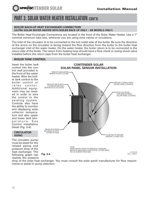
BOILER TANK CONTROL<br />
Insert the boiler tank<br />
control into the control<br />
well provided in<br />
the front of the water<br />
heater. Wire the boiler<br />
tank control to the<br />
boiler control or<br />
relay center.<br />
Additional equipment<br />
may be needed<br />
in order to wire<br />
the control to the<br />
existing system.<br />
Controls also have<br />
the ability to monitor<br />
and displaying solar<br />
collector temperature<br />
and also upper<br />
and lower tank temperature.<br />
See<br />
Control <strong>Installation</strong><br />
Detail (Fig. 3-4).<br />
CIRCULATOR<br />
SIZING<br />
The circulator pump<br />
must be sized for the<br />
related piping and<br />
pressure drop of the<br />
heat exchanger. The<br />
following graph represents<br />
the pressure<br />
REMOVE INSULATION<br />
BEHIND PLASTIC COVER<br />
REMOVE THE PLASTIC<br />
COVER PROTECTING<br />
SENSOR STUD LOCATION<br />
REMOVE SCREWS<br />
SECURING PLASTIC<br />
COVER TO TANK<br />
Fig. 3-4<br />
CONTENDER SOLAR<br />
SOLAR PANEL SENSOR INSTALLATION<br />
NOTE:<br />
WHEN INSTALLATION OF SENSOR IS COMPLETE,<br />
REPLACE INSULATION AND PLASTIC COVER USING<br />
THE (2) SCREWS PROVIDED<br />
SENSOR COMING FROM<br />
SOLAR PANEL CONTROL<br />
1/4-20 NUT TO SECURE<br />
SENSOR TO TANK STUD<br />
STUD LOCATION<br />
FOR SENSOR FROM<br />
SOLAR PANEL CONTROL<br />
LP-200-N<br />
REV. 7/26/07<br />
drop of the solar heat exchanger. You must consult the solar panel manufacturer for flow requirements<br />
to assist in pump selection.<br />
15