Catalyst 6500 Series Switches Installation Guide - Ipland
Catalyst 6500 Series Switches Installation Guide - Ipland Catalyst 6500 Series Switches Installation Guide - Ipland
Catalyst 6513-E Switch Chapter 1 Product Overview Table 1-24 lists the environmental and physical specifications of the Catalyst 6513-E switch chassis. Table 1-24 Catalyst 6513-E Switch Specifications Item Environmental Temperature, operating Temperature, nonoperating and storage Thermal transition Humidity (RH), ambient (noncondensing) operating Humidity (RH), ambient (noncondensing) nonoperating and storage Specification Certified for operation: 32° to 104°F (0° to 40°C) Designed and tested for operation: 32° to 131°F (0° to 55°C) Note The Catalyst 6500 series switches are equipped with internal air temperature sensors that are triggered at 104°F (40°C) generating a minor alarm and at 131°F (55°C) generating a major alarm. Chassis unpackaged: –4° to 149°F (–20° to 65°C) Chassis in protective shipping package: –40° to 158°F (–40° to 70°C) 0.5°C per minute (hot to cold) 0.33°C per minute (cold to hot) 5% to 90% 5% to 95% Altitude, operating Certified for operation: 0 to 6500 ft (0 to 2000 m) Shock and vibration Designed and tested for operation: –200 to 10,000 ft (–60 to 3000 m) This switch complies with Network Equipment Building Systems (NEBS) (Zone 4 per GR-63-Core) in the following areas: • Earthquake environment and criteria • Office vibration and criteria • Transportation vibration and criteria Shock • Operational—5 G 30 ms, half-sine (IEC 68-2-27) • Nonoperational—20 G, 7.5 ms, trapezoidal Vibration Operational—3 Hz to 500 Hz. Power Spectral Density (PSD)—0.0005 G 2 /Hz at 10 Hz and 200 Hz. 5 dB/octave roll off at each end. 0.5 hours per axis (1.12 Grms). Acoustic noise 61.4 to 77 dB. International Organization for Standardization (ISO) 7779: Bystander position operating to an ambient temperature of 86°F (30°C). 1-72 Catalyst 6500 Series Switches Installation Guide OL-5781-08
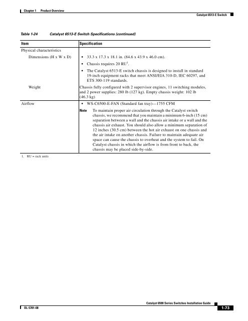
Chapter 1 Product Overview Catalyst 6513-E Switch Table 1-24 Catalyst 6513-E Switch Specifications (continued) Item Specification Physical characteristics Dimensions (H x W x D) • 33.3 x 17.3 x 18.1 in. (84.6 x 43.9 x 46.0 cm). • Chassis requires 20 RU 1 . • The Catalyst 6513-E switch chassis is designed to install in standard 19-inch equipment racks that meet ANSI/EIA 310-D, IEC 60297, and ETS 300-119 standards. Weight Chassis fully configured with 2 supervisor engines, 11 switching modules, and 2 power supplies: 280 lb (127 kg). Empty chassis weight: 102 lb (46.3 kg) Airflow • WS-C6500-E-FAN (Standard fan tray)—1755 CFM 1. RU = rack units Note To maintain proper air circulation through the Catalyst switch chassis, we recommend that you maintain a minimum 6-inch (15 cm) separation between a wall and the chassis air intake or a wall and the chassis air exhaust. You should also allow a minimum separation of 12 inches (30.5 cm) between the hot air exhaust on one chassis and the air intake on another chassis. Failure to maintain adequate air space can cause the chassis to overheat and the system to fail. On Catalyst chassis in which the airflow is from front to back, the chassis may be placed side-by-side. OL-5781-08 Catalyst 6500 Series Switches Installation Guide 1-73
- Page 42 and 43: Catalyst 6506 Switch Chapter 1 Prod
- Page 44 and 45: WS-X6408 8 PORT GIGABIT ETHERNET WS
- Page 46 and 47: Catalyst 6506-E Switch Chapter 1 Pr
- Page 48 and 49: Catalyst 6506-E Switch Chapter 1 Pr
- Page 50 and 51: WS-X6408 WS-X6408 WS-X6408 WS-X6408
- Page 52 and 53: Catalyst 6509 Switch Chapter 1 Prod
- Page 54 and 55: Catalyst 6509 Switch Chapter 1 Prod
- Page 56 and 57: WS-X6408 WS-X6408 WS-X6408 WS-X6408
- Page 58 and 59: Catalyst 6509-E Switch Chapter 1 Pr
- Page 60 and 61: Catalyst 6509-E Switch Chapter 1 Pr
- Page 62 and 63: FAN STATUS LINK LINK LINK LINK LINK
- Page 64 and 65: Catalyst 6509-NEB Switch Chapter 1
- Page 66 and 67: Catalyst 6509-NEB Switch Chapter 1
- Page 68 and 69: Catalyst 6509-NEB Switch Chapter 1
- Page 70 and 71: Catalyst 6509-NEB-A Switch Chapter
- Page 72 and 73: Catalyst 6509-NEB-A Switch Chapter
- Page 74 and 75: Catalyst 6509-NEB-A Switch Chapter
- Page 76 and 77: Catalyst 6509-V-E Switch Chapter 1
- Page 78 and 79: Catalyst 6509-V-E Switch Chapter 1
- Page 80 and 81: Catalyst 6509-V-E Switch Chapter 1
- Page 82 and 83: Catalyst 6513 Switch Chapter 1 Prod
- Page 84 and 85: Catalyst 6513 Switch Chapter 1 Prod
- Page 86 and 87: Catalyst 6513 Switch Chapter 1 Prod
- Page 88 and 89: WS-X6408 8 PORT GIGABIT ETHERNET WS
- Page 90 and 91: Catalyst 6513-E Switch Chapter 1 Pr
- Page 94 and 95: Catalyst 6513-E Switch Chapter 1 Pr
- Page 96 and 97: Safety Chapter 2 Preparing for Inst
- Page 98 and 99: Site Requirements Chapter 2 Prepari
- Page 100 and 101: WS-X6K-SUP2-2GE OSM-4OC12 POS-SI 4
- Page 102 and 103: WS-X6K-SUP2-2GE SUPERVISOR2 WS-X6K-
- Page 104 and 105: WS-X6K-SUP2-2GE SUPERVISOR2 WS-X6K-
- Page 106 and 107: 1 2 3 4 5 6 7 8 9 10 1 1 2 12 3 4 5
- Page 108 and 109: WS-X6408 8 PORT GIGABIT ETHERNET WS
- Page 110 and 111: Site Requirements Chapter 2 Prepari
- Page 112 and 113: Site Requirements Chapter 2 Prepari
- Page 114 and 115: Site Requirements Chapter 2 Prepari
- Page 116 and 117: Power Requirements Chapter 2 Prepar
- Page 118 and 119: Cabling Requirements Chapter 2 Prep
- Page 120 and 121: Site Preparation Checklist Chapter
- Page 122 and 123: Chapter 3 Installing the Switch The
- Page 124 and 125: Rack-Mounting Guidelines Chapter 3
- Page 126 and 127: Chassis Installation Kits and Cable
- Page 128 and 129: Installing a Catalyst 6503 or Catal
- Page 130 and 131: CAUTION STATUS LINK CONSOLE LINK LI
- Page 132 and 133: Installing a Catalyst 6504-E Switch
- Page 134 and 135: WS-SUP32-GE-3B CAUTION STATUS LINK
- Page 136 and 137: Installing a Catalyst 6504-E Switch
- Page 138 and 139: WS-X6408 8 PORT GIGABIT ETHERNET WS
- Page 140 and 141: WS-X6408 8 PORT GIGABIT ETHERNET WS
Chapter 1<br />
Product Overview<br />
<strong>Catalyst</strong> 6513-E Switch<br />
Table 1-24<br />
<strong>Catalyst</strong> 6513-E Switch Specifications (continued)<br />
Item<br />
Specification<br />
Physical characteristics<br />
Dimensions (H x W x D) • 33.3 x 17.3 x 18.1 in. (84.6 x 43.9 x 46.0 cm).<br />
• Chassis requires 20 RU 1 .<br />
• The <strong>Catalyst</strong> 6513-E switch chassis is designed to install in standard<br />
19-inch equipment racks that meet ANSI/EIA 310-D, IEC 60297, and<br />
ETS 300-119 standards.<br />
Weight<br />
Chassis fully configured with 2 supervisor engines, 11 switching modules,<br />
and 2 power supplies: 280 lb (127 kg). Empty chassis weight: 102 lb<br />
(46.3 kg)<br />
Airflow • WS-C<strong>6500</strong>-E-FAN (Standard fan tray)—1755 CFM<br />
1. RU = rack units<br />
Note<br />
To maintain proper air circulation through the <strong>Catalyst</strong> switch<br />
chassis, we recommend that you maintain a minimum 6-inch (15 cm)<br />
separation between a wall and the chassis air intake or a wall and the<br />
chassis air exhaust. You should also allow a minimum separation of<br />
12 inches (30.5 cm) between the hot air exhaust on one chassis and<br />
the air intake on another chassis. Failure to maintain adequate air<br />
space can cause the chassis to overheat and the system to fail. On<br />
<strong>Catalyst</strong> chassis in which the airflow is from front to back, the<br />
chassis may be placed side-by-side.<br />
OL-5781-08<br />
<strong>Catalyst</strong> <strong>6500</strong> <strong>Series</strong> <strong>Switches</strong> <strong>Installation</strong> <strong>Guide</strong><br />
1-73


