Catalyst 6500 Series Switches Installation Guide - Ipland
Catalyst 6500 Series Switches Installation Guide - Ipland Catalyst 6500 Series Switches Installation Guide - Ipland
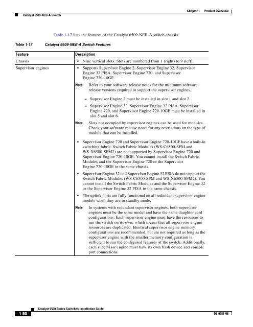
Catalyst 6509-NEB-A Switch Chapter 1 Product Overview Table 1-17 lists the features of the Catalyst 6509-NEB-A switch chassis. Table 1-17 Catalyst 6509-NEB-A Switch Features Feature Description Chassis • Nine vertical slots. Slots are numbered from 1 (right) to 9 (left). Supervisor engines • Supports Supervisor Engine 2, Supervisor Engine 32, Supervisor Engine 32 PISA, Supervisor Engine 720, and Supervisor Engine 720-10GE. Note Refer to your software release notes for the minimum software release versions required to support the supervisor engines. Note – Supervisor Engine 2 must be installed in slot 1 and slot 2. – Supervisor Engine 32, Supervisor Engine 32 PISA, Supervisor Engine 720, and Supervisor Engine 720-10GE must be installed in slot 5 and slot 6. Slots not occupied by supervisor engines can be used for modules. Check your software release notes for any restrictions on the type of module that can be installed. • Supervisor Engine 720 and Supervisor Engine 720-10GE have a built-in switching fabric. Switch Fabric Modules (WS-C6500-SFM and WS-X6500-SFM2) are not supported by Supervisor Engine 720 and Supervisor Engine 720-10GE. You cannot install the Switch Fabric Modules and the Supervisor Engine 720 or the Supervisor Engine 720-10GE in the same chassis. • Supervisor Engine 32 and Supervisor Engine 32 PISA do not support the Switch Fabric Modules (WS-C6500-SFM and WS-X6500-SFM2). You cannot install the Switch Fabric Modules and the Supervisor Engine 32 or the Supervisor Engine 32 PISA in the same chassis. • The uplink ports are fully functional on all redundant supervisor engine models when they are in standby mode. Note In systems with redundant supervisor engines, both supervisor engines must be the same model and have the same daughter card configurations. Each supervisor engine must have the resources to run the switch on its own, which means that all supervisor engine resources are duplicated. Identical supervisor engine memory configurations are recommended, but are not required as long as the supervisor engine with the smaller memory configuration is sufficient to run the configured features of the switch. Additionally, each supervisor engine must have its own flash device and console port connections. 1-50 Catalyst 6500 Series Switches Installation Guide OL-5781-08
Chapter 1 Product Overview Catalyst 6509-NEB-A Switch Table 1-17 Catalyst 6509-NEB-A Switch Features (continued) Feature Description Modules • Supports up to eight Catalyst 6500 series modules. • WS-C6500-SFM and WS-X6500-SFM2 Switch Fabric Modules must be installed in slot 5 or slot 6. Note Mixing WS-C6500-SFM and WS-X6500-SFM2 Switch Fabric Modules in the Catalyst 6509-NEB-A chassis is allowed. • Some Catalyst 6500 series modules may: – Not be supported – Require that you install a Supervisor Engine 720 – Have chassis slot restrictions – Require a specific software release level to operate Note Check your software release notes for specific information. Backplane bandwidth • 32 GBps shared bus. • 256 GBps switch fabric. • 720 GBps switch fabric. Clock and VTT modules • Two replaceable clock modules (CLK-7600=) provide clocking signals to the EOBC channel and the switching bus. • Three replaceable voltage termination (VTT) modules (WS-C6K-VTT=) provide reference voltage for bus signals. Fan tray • The chassis supports two hot-swappable fan trays. With one fan tray installed, the chassis supports operating temperatures up to 104°F (40°C). With both fan trays installed, the chassis supports operating temperatures up to 131°F (55°C). One fan tray model is available: Note – FAN-MOD-09 (High-speed fan tray—760 CFM). Supports Supervisor Engine 2, Supervisor Engine 32, and Supervisor Engine 720. Each fan tray contains four individual fans. The individual fans are not field replaceable; you must replace the fan tray in the event of a fan failure. • Fan tray STATUS LED – Red—One or more individual fans have failed. – Green—Fan tray is operating normally. OL-5781-08 Catalyst 6500 Series Switches Installation Guide 1-51
- Page 20 and 21: Related Documentation Preface Obtai
- Page 22 and 23: WS-SUP32-GE-3B Catalyst 6503 Switch
- Page 24 and 25: Catalyst 6503 Switch Chapter 1 Prod
- Page 26 and 27: Catalyst 6503 Switch Chapter 1 Prod
- Page 28 and 29: WS-SUP32-GE-3B Catalyst 6503-E Swit
- Page 30 and 31: Catalyst 6503-E Switch Chapter 1 Pr
- Page 32 and 33: Catalyst 6503-E Switch Chapter 1 Pr
- Page 34 and 35: Catalyst 6504-E Switch Chapter 1 Pr
- Page 36 and 37: Catalyst 6504-E Switch Chapter 1 Pr
- Page 38 and 39: WS-X6408 8 PORT GIGABIT ETHERNET WS
- Page 40 and 41: Catalyst 6506 Switch Chapter 1 Prod
- Page 42 and 43: Catalyst 6506 Switch Chapter 1 Prod
- Page 44 and 45: WS-X6408 8 PORT GIGABIT ETHERNET WS
- Page 46 and 47: Catalyst 6506-E Switch Chapter 1 Pr
- Page 48 and 49: Catalyst 6506-E Switch Chapter 1 Pr
- Page 50 and 51: WS-X6408 WS-X6408 WS-X6408 WS-X6408
- Page 52 and 53: Catalyst 6509 Switch Chapter 1 Prod
- Page 54 and 55: Catalyst 6509 Switch Chapter 1 Prod
- Page 56 and 57: WS-X6408 WS-X6408 WS-X6408 WS-X6408
- Page 58 and 59: Catalyst 6509-E Switch Chapter 1 Pr
- Page 60 and 61: Catalyst 6509-E Switch Chapter 1 Pr
- Page 62 and 63: FAN STATUS LINK LINK LINK LINK LINK
- Page 64 and 65: Catalyst 6509-NEB Switch Chapter 1
- Page 66 and 67: Catalyst 6509-NEB Switch Chapter 1
- Page 68 and 69: Catalyst 6509-NEB Switch Chapter 1
- Page 72 and 73: Catalyst 6509-NEB-A Switch Chapter
- Page 74 and 75: Catalyst 6509-NEB-A Switch Chapter
- Page 76 and 77: Catalyst 6509-V-E Switch Chapter 1
- Page 78 and 79: Catalyst 6509-V-E Switch Chapter 1
- Page 80 and 81: Catalyst 6509-V-E Switch Chapter 1
- Page 82 and 83: Catalyst 6513 Switch Chapter 1 Prod
- Page 84 and 85: Catalyst 6513 Switch Chapter 1 Prod
- Page 86 and 87: Catalyst 6513 Switch Chapter 1 Prod
- Page 88 and 89: WS-X6408 8 PORT GIGABIT ETHERNET WS
- Page 90 and 91: Catalyst 6513-E Switch Chapter 1 Pr
- Page 92 and 93: Catalyst 6513-E Switch Chapter 1 Pr
- Page 94 and 95: Catalyst 6513-E Switch Chapter 1 Pr
- Page 96 and 97: Safety Chapter 2 Preparing for Inst
- Page 98 and 99: Site Requirements Chapter 2 Prepari
- Page 100 and 101: WS-X6K-SUP2-2GE OSM-4OC12 POS-SI 4
- Page 102 and 103: WS-X6K-SUP2-2GE SUPERVISOR2 WS-X6K-
- Page 104 and 105: WS-X6K-SUP2-2GE SUPERVISOR2 WS-X6K-
- Page 106 and 107: 1 2 3 4 5 6 7 8 9 10 1 1 2 12 3 4 5
- Page 108 and 109: WS-X6408 8 PORT GIGABIT ETHERNET WS
- Page 110 and 111: Site Requirements Chapter 2 Prepari
- Page 112 and 113: Site Requirements Chapter 2 Prepari
- Page 114 and 115: Site Requirements Chapter 2 Prepari
- Page 116 and 117: Power Requirements Chapter 2 Prepar
- Page 118 and 119: Cabling Requirements Chapter 2 Prep
<strong>Catalyst</strong> 6509-NEB-A Switch<br />
Chapter 1<br />
Product Overview<br />
Table 1-17 lists the features of the <strong>Catalyst</strong> 6509-NEB-A switch chassis.<br />
Table 1-17<br />
<strong>Catalyst</strong> 6509-NEB-A Switch Features<br />
Feature<br />
Description<br />
Chassis • Nine vertical slots. Slots are numbered from 1 (right) to 9 (left).<br />
Supervisor engines • Supports Supervisor Engine 2, Supervisor Engine 32, Supervisor<br />
Engine 32 PISA, Supervisor Engine 720, and Supervisor<br />
Engine 720-10GE.<br />
Note<br />
Refer to your software release notes for the minimum software<br />
release versions required to support the supervisor engines.<br />
Note<br />
– Supervisor Engine 2 must be installed in slot 1 and slot 2.<br />
– Supervisor Engine 32, Supervisor Engine 32 PISA, Supervisor<br />
Engine 720, and Supervisor Engine 720-10GE must be installed in<br />
slot 5 and slot 6.<br />
Slots not occupied by supervisor engines can be used for modules.<br />
Check your software release notes for any restrictions on the type of<br />
module that can be installed.<br />
• Supervisor Engine 720 and Supervisor Engine 720-10GE have a built-in<br />
switching fabric. Switch Fabric Modules (WS-C<strong>6500</strong>-SFM and<br />
WS-X<strong>6500</strong>-SFM2) are not supported by Supervisor Engine 720 and<br />
Supervisor Engine 720-10GE. You cannot install the Switch Fabric<br />
Modules and the Supervisor Engine 720 or the Supervisor<br />
Engine 720-10GE in the same chassis.<br />
• Supervisor Engine 32 and Supervisor Engine 32 PISA do not support the<br />
Switch Fabric Modules (WS-C<strong>6500</strong>-SFM and WS-X<strong>6500</strong>-SFM2). You<br />
cannot install the Switch Fabric Modules and the Supervisor Engine 32<br />
or the Supervisor Engine 32 PISA in the same chassis.<br />
• The uplink ports are fully functional on all redundant supervisor engine<br />
models when they are in standby mode.<br />
Note<br />
In systems with redundant supervisor engines, both supervisor<br />
engines must be the same model and have the same daughter card<br />
configurations. Each supervisor engine must have the resources to<br />
run the switch on its own, which means that all supervisor engine<br />
resources are duplicated. Identical supervisor engine memory<br />
configurations are recommended, but are not required as long as the<br />
supervisor engine with the smaller memory configuration is<br />
sufficient to run the configured features of the switch. Additionally,<br />
each supervisor engine must have its own flash device and console<br />
port connections.<br />
1-50<br />
<strong>Catalyst</strong> <strong>6500</strong> <strong>Series</strong> <strong>Switches</strong> <strong>Installation</strong> <strong>Guide</strong><br />
OL-5781-08


