Catalyst 6500 Series Switches Installation Guide - Ipland
Catalyst 6500 Series Switches Installation Guide - Ipland Catalyst 6500 Series Switches Installation Guide - Ipland
Installing the Remote Power Cycling Feature Control Wires (Optional) Chapter 4 Removal and Replacement Procedures Figure 4-78 Installing the Relay Control Wires o INPUT OK FAN OK OUTPUT FAIL NC RELAY CISCO SYSTEMS, INC. 1 2 3 220VAC 1 2 3 DEFAULT NO RELAY Small flat-blade screwdriver 1 2 3 Controller wires 182183 Step 8 Check the position of the relay controller switch located next to the terminal block. The switch should be in the down, NO (normally open) position if the relay controller box uses a NO relay. This the default and the recommended position. If the relay controller box uses a NC relay, the relay controller switch should be in the up position. You are now ready to install the ferrite bead on the control wires. Follow the installation instructions supplied in the package containing the ferrite bead or the installation procedure in the next section. Installing the Ferrite Bead The ferrite bead is a passive device that limits high-frequency interference on interface and control cables, and it is only required when you install the remote power-cycling feature that is supported only by the 8700 Watt power supply. The ferrite bead is installed on the two control wires that link the external relay controller box with the remote power-cycling terminal block on the 8700 W power supply. You do not need the ferrite bead for 8700 Watt power supply installations that do not include the remote power-cycling feature. 4-100 Catalyst 6500 Series Switches Installation Guide OL-5781-08
Chapter 4 Removal and Replacement Procedures Installing the Remote Power Cycling Feature Control Wires (Optional) To install the ferrite bead on the remote power-cycling control wires, follow these steps: Step 1 Remove the ferrite bead and the two plastic ties from the plastic bag. Step 2 Open the ferrite bead as shown in Figure 4-79, View A. Step 3 Place the two remote power-cycling control wires (18 AWG maximum) in the ferrite bead as shown in Figure 4-79, View B. Close the ferrite bead making sure that the two halves have completely snapped together and are secure. Step 4 Locate a point on the remote power-cycling control wires that leaves approximately 1 to 2 inches (2.5 to 5 cm) of exposed wire from the remote power cycling terminal block located on the front of the power supply. Wrap one of the 4-inch plastic ties around the remote power-cycling control wires at that point. Tighten the plastic tie so that it is snug against the control wires and cannot slide. See Figure 4-79, View C. Step 5 Step 6 Slide the ferrite bead so that it is positioned just behind the first plastic tie wrap. Take the second plastic tie and wrap it around the control wires directly behind the ferrite bead and tighten it so that the ferrite bead cannot slide up or down the control wires. See Figure 4-79, View C. To finish the procedure, trim the excess plastic strap from the two plastic tie wraps. Figure 4-79 Installing the Ferrite Bead View A View B Ferrite bead open View C Approximately 1 to 2 inches (2.5 to 5 cm) To power supply remote power on/off terminal block Tie wrap Ferrite bead Tie wrap 181876 OL-5781-08 Catalyst 6500 Series Switches Installation Guide 4-101
- Page 256 and 257: Removing and Installing the DC-Inpu
- Page 258 and 259: Removing and Installing the DC-Inpu
- Page 260 and 261: Removing and Installing the DC-Inpu
- Page 262 and 263: Removing and Installing the DC-Inpu
- Page 264 and 265: Removing and Installing the DC-Inpu
- Page 266 and 267: CISCO SYSTEMS, INC Removing and Ins
- Page 268 and 269: CISCO SYSTEMS, INC 1 2 3 4 INPUT OK
- Page 270 and 271: Removing and Installing the DC-Inpu
- Page 272 and 273: CISCO SYSTEMS, INC Removing and Ins
- Page 274 and 275: Removing and Installing the DC-Inpu
- Page 276 and 277: Removing and Installing the DC-Inpu
- Page 278 and 279: Removing and Installing the DC-Inpu
- Page 280 and 281: CISCO SYSTEMS, INC 1 2 3 4 INPUT OK
- Page 282 and 283: Removing and Installing PEMs Chapte
- Page 284 and 285: Removing and Installing PEMs Chapte
- Page 286 and 287: OSM-4OC12 POS-SI 1 2 1 2 1 1 2 2 3
- Page 288 and 289: Removing and Installing the Fan Tra
- Page 290 and 291: WS-X6K-SUP2-2GE OSM-4OC12 POS-SI OS
- Page 292 and 293: WS-X6K-SUP2-2GE SUPERVISOR2 WS-X6K-
- Page 294 and 295: WS-C6500-SFM SWITCH FABRIC MDL WS-C
- Page 296 and 297: WS-X6K-SUP2-2GE SUPERVISOR2 WS-X6K-
- Page 298 and 299: Removing and Installing the Fan Tra
- Page 300 and 301: ACTIVE TX RX RX TX ACTIVE TX RX RX
- Page 302 and 303: Installing the Air Filter Assembly
- Page 304 and 305: Installing the Remote Power Cycling
- Page 308 and 309: Installing the Remote Power Cycling
- Page 310 and 311: Power Supply Compatibility Matrix A
- Page 312 and 313: Power Supply Compatibility Matrix A
- Page 314 and 315: 950 W AC-Input and DC-Input Power S
- Page 316 and 317: 950 W AC-Input and DC-Input Power S
- Page 318 and 319: 1000 W AC-Input Power Supply Append
- Page 320 and 321: 1000 W AC-Input Power Supply Append
- Page 322 and 323: 1300 W AC-Input and DC-Input Power
- Page 324 and 325: 1300 W AC-Input and DC-Input Power
- Page 326 and 327: 1400 W AC-Input Power Supply Append
- Page 328 and 329: 1400 W AC-Input Power Supply Append
- Page 330 and 331: 1400 W AC-Input Power Supply Append
- Page 332 and 333: 2500 W AC-Input and DC-Input Power
- Page 334 and 335: 2500 W AC-Input and DC-Input Power
- Page 336 and 337: 2500 W AC-Input and DC-Input Power
- Page 338 and 339: 2700 W AC-Input and DC-Input Power
- Page 340 and 341: 2700 W AC-Input and DC-Input Power
- Page 342 and 343: 2700 W AC-Input and DC-Input Power
- Page 344 and 345: 3000 W AC-Input Power Supply Append
- Page 346 and 347: 3000 W AC-Input Power Supply Append
- Page 348 and 349: 3000 W AC-Input Power Supply Append
- Page 350 and 351: 4000 W AC-Input and DC-Input Power
- Page 352 and 353: 4000 W AC-Input and DC-Input Power
- Page 354 and 355: 6000 W AC-Input and DC-Input Power
Chapter 4<br />
Removal and Replacement Procedures<br />
Installing the Remote Power Cycling Feature Control Wires (Optional)<br />
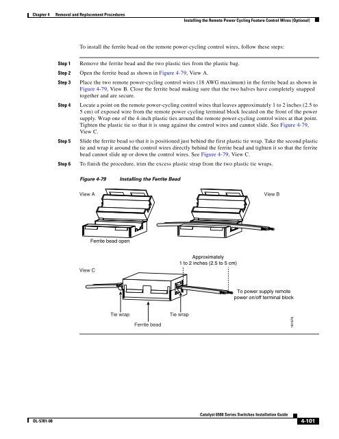
To install the ferrite bead on the remote power-cycling control wires, follow these steps:<br />
Step 1 Remove the ferrite bead and the two plastic ties from the plastic bag.<br />
Step 2 Open the ferrite bead as shown in Figure 4-79, View A.<br />
Step 3 Place the two remote power-cycling control wires (18 AWG maximum) in the ferrite bead as shown in<br />
Figure 4-79, View B. Close the ferrite bead making sure that the two halves have completely snapped<br />
together and are secure.<br />
Step 4 Locate a point on the remote power-cycling control wires that leaves approximately 1 to 2 inches (2.5 to<br />
5 cm) of exposed wire from the remote power cycling terminal block located on the front of the power<br />
supply. Wrap one of the 4-inch plastic ties around the remote power-cycling control wires at that point.<br />
Tighten the plastic tie so that it is snug against the control wires and cannot slide. See Figure 4-79,<br />
View C.<br />
Step 5<br />
Step 6<br />
Slide the ferrite bead so that it is positioned just behind the first plastic tie wrap. Take the second plastic<br />
tie and wrap it around the control wires directly behind the ferrite bead and tighten it so that the ferrite<br />
bead cannot slide up or down the control wires. See Figure 4-79, View C.<br />
To finish the procedure, trim the excess plastic strap from the two plastic tie wraps.<br />
Figure 4-79<br />
Installing the Ferrite Bead<br />
View A<br />
View B<br />
Ferrite bead open<br />
View C<br />
Approximately<br />
1 to 2 inches (2.5 to 5 cm)<br />
To power supply remote<br />
power on/off terminal block<br />
Tie wrap<br />
Ferrite bead<br />
Tie wrap<br />
181876<br />
OL-5781-08<br />
<strong>Catalyst</strong> <strong>6500</strong> <strong>Series</strong> <strong>Switches</strong> <strong>Installation</strong> <strong>Guide</strong><br />
4-101


