Catalyst 6500 Series Switches Installation Guide - Ipland
Catalyst 6500 Series Switches Installation Guide - Ipland Catalyst 6500 Series Switches Installation Guide - Ipland
Removing and Installing the DC-Input Power Supplies Chapter 4 Removal and Replacement Procedures Caution Step 20 Step 21 Step 22 To prevent a short circuit or shock hazard after wiring the DC-input power supply, reinstall the terminal block covers. After you confirm that all installation steps are completed correctly, remove any safety flags, lockout devices, or adhesive tape from the source DC circuit breakers, and energize the input circuits to the power supplies. Turn the power switch to the on (|) position on the power supply. Turning on the power switch also engages a pawl that locks the power supply in the chassis. Verify the power supply operation by ensuring that the power supply front panel LEDs are in the following states: • INPUT OK 1 LED—If you have source DC cables attached to the VE-1 pair of power supply inputs, verify that the LED is green. If source DC cables are attached and the LED is not lit, source DC might not be on or the source DC voltage is less than or equal to –33 VDC. If the source DC voltage is between –33 VDC and –40.5 VDC, the LED can be either on, off, or flashing. • INPUT OK 2 LED—If you have source DC cables attached to the VE-2 pair of power supply inputs, verify that the LED is green. If source DC cables are attached and the LED is not lit, source DC might not be on or the source DC voltage is less than or equal to –33 VDC. If the source DC voltage is between –33 VDC and –40.5 VDC, the LED can be either on, off, or flashing. • INPUT OK 3 LED—If you have source DC cables attached to the VE-3 pair of power supply inputs, verify that the LED is green. If source DC cables are attached and the LED is not lit, source DC might not be on or the source DC voltage is less than or equal to –33 VDC. If the source DC voltage is between –33 VDC and –40.5 VDC, the LED can be either on, off, or flashing. • FAN OK LED is green. • OUTPUT FAIL LED is not lit. If the LEDs indicate a power problem, see the “Identifying Startup Problems” section on page E-3. Installing the 4000 W Power Supply (Wiring for 4000 W Operation; Right Power Bay) See Figure 4-26 for item location and identification on the 4000 W DC-input power supply. Note You should allow a minimum of 2.5 to 3 inches (63.5 mm to 76.2 mm) of space between the side of the power supply and any obstructions (such as the side of an enclosed equipment rack). This space is needed to install and secure the DC-input power cables correctly. Incorrectly routing the DC-input power cables can cause airflow blockage into the power supply and inadequate strain relief in the cables. The exact amount of space required depends upon the gauge and flexibility of the DC-input power cables you are using. Note For proper 4000 W DC-input redundant power configurations, source DC for one 4000 W DC-input power supply must come from the same battery system (A feed); source DC for the other 4000 W DC-input power supply must come from another battery system (B feed). 4-54 Catalyst 6500 Series Switches Installation Guide OL-5781-08
Chapter 4 Removal and Replacement Procedures Removing and Installing the DC-Input Power Supplies Note For multiple DC-input power supplies, each DC input must be protected by a dedicated circuit breaker or a fuse. The circuit breaker or fuse must be sized according to the power supply input rating and the local or national electrical code requirements. To install a 4000 W DC-input power supply and wire it for 4000 W operation in the right power bay (POWER 2), follow these steps: Step 1 Step 2 Step 3 Ensure that the system (earth) ground connection has been made. For ground connection installation instructions, see the “Establishing the System Ground” section on page 3-52. Verify that source DC power is off to the DC circuit that feeds the power supply that you are installing. As an added precaution, place the appropriate safety flag and lockout devices at the source power circuit breaker, or place a piece of adhesive tape over the circuit breaker handle to prevent accidental power restoration while you are working on the circuit. Prepare the source DC-input power cables by attaching the appropriately sized lugs. The power supply terminal block lug opening width is 0.62 inch (15.8 mm). The terminal posts are centered 0.63 inches (15.88 mm) apart and have a 1/4-20 thread. We recommend that you use an appropriately sized industry standard 2-hole, standard barrel compression lug. (See Figure 4-38.) The power supply ground posts, located below the terminal block, also have 1/4-20 threads and require two 1/4-inch split-ring washers and two 1/4-20 hex nuts. The DC-input wires and the DC power supply ground wires should be sized according to the local and national installation requirements. Use only copper wire. For North American installations, use 90°C-rated, fine-strand copper conductors. Figure 4-38 DC Power Cable Lug 2.25 Ø .267 2 holes .25 .63 .37 Crimp area All measurements in inches 120563 Caution Step 4 Use both hands to install and remove power supplies. Each DC-input power supply weighs 32 pounds (14.5 kg). Grasp the power supply handle with one hand, and place your other hand underneath the power supply. Slide the power supply into the power supply bay. Make sure that the power supply is fully seated in the bay. (See Figure 4-39.) OL-5781-08 Catalyst 6500 Series Switches Installation Guide 4-55
- Page 210 and 211: OSM-4OC12 POS-SI 2 1 2 1 4 2 3 1 4
- Page 212 and 213: Removing and Installing the AC-Inpu
- Page 214 and 215: ALL FASTENERS MUST BE FULLY ENGAGED
- Page 216 and 217: Removing and Installing the AC-Inpu
- Page 218 and 219: WS-X6K-SUP2-2GE SUPERVISOR2 WS-X6K-
- Page 220 and 221: Removing and Installing the AC-Inpu
- Page 222 and 223: OSM-4OC12 POS-SI 1 2 1 2 1 1 2 2 3
- Page 224 and 225: Removing and Installing the DC-Inpu
- Page 226 and 227: Removing and Installing the DC-Inpu
- Page 228 and 229: Removing and Installing the DC-Inpu
- Page 230 and 231: Removing and Installing the DC-Inpu
- Page 232 and 233: Removing and Installing the DC-Inpu
- Page 234 and 235: Removing and Installing the DC-Inpu
- Page 236 and 237: Removing and Installing the DC-Inpu
- Page 238 and 239: Removing and Installing the DC-Inpu
- Page 240 and 241: Removing and Installing the DC-Inpu
- Page 242 and 243: Removing and Installing the DC-Inpu
- Page 244 and 245: Removing and Installing the DC-Inpu
- Page 246 and 247: Removing and Installing the DC-Inpu
- Page 248 and 249: Removing and Installing the DC-Inpu
- Page 250 and 251: Removing and Installing the DC-Inpu
- Page 252 and 253: Removing and Installing the DC-Inpu
- Page 254 and 255: Removing and Installing the DC-Inpu
- Page 256 and 257: Removing and Installing the DC-Inpu
- Page 258 and 259: Removing and Installing the DC-Inpu
- Page 262 and 263: Removing and Installing the DC-Inpu
- Page 264 and 265: Removing and Installing the DC-Inpu
- Page 266 and 267: CISCO SYSTEMS, INC Removing and Ins
- Page 268 and 269: CISCO SYSTEMS, INC 1 2 3 4 INPUT OK
- Page 270 and 271: Removing and Installing the DC-Inpu
- Page 272 and 273: CISCO SYSTEMS, INC Removing and Ins
- Page 274 and 275: Removing and Installing the DC-Inpu
- Page 276 and 277: Removing and Installing the DC-Inpu
- Page 278 and 279: Removing and Installing the DC-Inpu
- Page 280 and 281: CISCO SYSTEMS, INC 1 2 3 4 INPUT OK
- Page 282 and 283: Removing and Installing PEMs Chapte
- Page 284 and 285: Removing and Installing PEMs Chapte
- Page 286 and 287: OSM-4OC12 POS-SI 1 2 1 2 1 1 2 2 3
- Page 288 and 289: Removing and Installing the Fan Tra
- Page 290 and 291: WS-X6K-SUP2-2GE OSM-4OC12 POS-SI OS
- Page 292 and 293: WS-X6K-SUP2-2GE SUPERVISOR2 WS-X6K-
- Page 294 and 295: WS-C6500-SFM SWITCH FABRIC MDL WS-C
- Page 296 and 297: WS-X6K-SUP2-2GE SUPERVISOR2 WS-X6K-
- Page 298 and 299: Removing and Installing the Fan Tra
- Page 300 and 301: ACTIVE TX RX RX TX ACTIVE TX RX RX
- Page 302 and 303: Installing the Air Filter Assembly
- Page 304 and 305: Installing the Remote Power Cycling
- Page 306 and 307: Installing the Remote Power Cycling
- Page 308 and 309: Installing the Remote Power Cycling
Chapter 4<br />
Removal and Replacement Procedures<br />
Removing and Installing the DC-Input Power Supplies<br />
Note<br />
For multiple DC-input power supplies, each DC input must be protected by a dedicated circuit breaker<br />
or a fuse. The circuit breaker or fuse must be sized according to the power supply input rating and the<br />
local or national electrical code requirements.<br />
To install a 4000 W DC-input power supply and wire it for 4000 W operation in the right power bay<br />
(POWER 2), follow these steps:<br />
Step 1<br />
Step 2<br />
Step 3<br />
Ensure that the system (earth) ground connection has been made. For ground connection installation<br />
instructions, see the “Establishing the System Ground” section on page 3-52.<br />
Verify that source DC power is off to the DC circuit that feeds the power supply that you are installing.<br />
As an added precaution, place the appropriate safety flag and lockout devices at the source power circuit<br />
breaker, or place a piece of adhesive tape over the circuit breaker handle to prevent accidental power<br />
restoration while you are working on the circuit.<br />
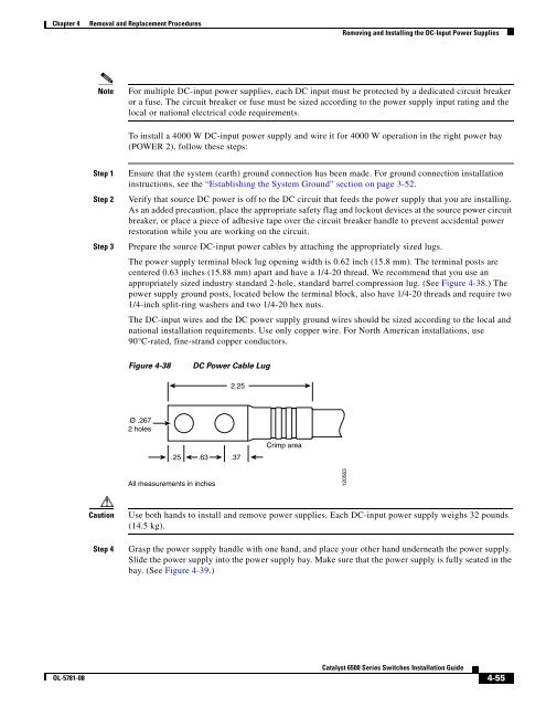
Prepare the source DC-input power cables by attaching the appropriately sized lugs.<br />
The power supply terminal block lug opening width is 0.62 inch (15.8 mm). The terminal posts are<br />
centered 0.63 inches (15.88 mm) apart and have a 1/4-20 thread. We recommend that you use an<br />
appropriately sized industry standard 2-hole, standard barrel compression lug. (See Figure 4-38.) The<br />
power supply ground posts, located below the terminal block, also have 1/4-20 threads and require two<br />
1/4-inch split-ring washers and two 1/4-20 hex nuts.<br />
The DC-input wires and the DC power supply ground wires should be sized according to the local and<br />
national installation requirements. Use only copper wire. For North American installations, use<br />
90°C-rated, fine-strand copper conductors.<br />
Figure 4-38<br />
DC Power Cable Lug<br />
2.25<br />
Ø .267<br />
2 holes<br />
.25 .63 .37<br />
Crimp area<br />
All measurements in inches<br />
120563<br />
Caution<br />
Step 4<br />
Use both hands to install and remove power supplies. Each DC-input power supply weighs 32 pounds<br />
(14.5 kg).<br />
Grasp the power supply handle with one hand, and place your other hand underneath the power supply.<br />
Slide the power supply into the power supply bay. Make sure that the power supply is fully seated in the<br />
bay. (See Figure 4-39.)<br />
OL-5781-08<br />
<strong>Catalyst</strong> <strong>6500</strong> <strong>Series</strong> <strong>Switches</strong> <strong>Installation</strong> <strong>Guide</strong><br />
4-55


