Catalyst 6500 Series Switches Installation Guide - Ipland
Catalyst 6500 Series Switches Installation Guide - Ipland Catalyst 6500 Series Switches Installation Guide - Ipland
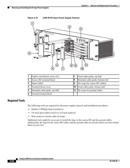
Removing and Installing the DC-Input Power Supplies Chapter 4 Removal and Replacement Procedures Figure 4-18 2700 W DC-Input Power Supply Features 1 2 3 PWR-2700-DC/4 -VE-1 -VE-1 INPUT1 INPUT2 FAN OUTPUT OK OK OK FAIL 48V-60V 48V-60V =40A =40A -VE-2 -VE-2 4 ALL FASTENERS MUST BE FULLY ENGAGED PRIOR TO OPERATING THE POWER SUPPLY 132219 6 5 7 8 9 10 11 1 Captive installation screw (4x) 7 Fixed cable guide, top half 2 Source DC terminal block 8 Detached cable guide, bottom half 3 Status LEDs 9 Tie wrap (for source DC cables) 4 Terminal block cover 10 Fixed cable guide, bottom half 5 Detached cable guide, top half 11 Tie wrap (for ground cable) 6 Ground terminal block Required Tools The following tools are required for the power supply removal and installation procedures: • Number 2 Phillips-head screwdriver • 1/4-inch open-ended wrench or 1/4-inch nutdriver • Wire cutters to cut the cable tie wraps Additional tools might be necessary to install the lugs on the source DC and the ground cables. Additionally, the lugs for the source DC cables and the ground cable are not provided; you must obtain them on your own. 4-28 Catalyst 6500 Series Switches Installation Guide OL-5781-08
Chapter 4 Removal and Replacement Procedures Removing and Installing the DC-Input Power Supplies Removing a 2700 W DC-Input Power Supply Warning Before performing any of the following procedures, ensure that power is removed from the DC circuits. To ensure that all power is removed, locate the circuit breakers or fuses on the DC power lines that service the DC circuits. Turn OFF the DC power line circuit breakers and remove the DC power line fuses. Statement 322 Warning Voltage is present on the backplane when the system is operating. To reduce risk of an electric shock, keep hands and fingers out of the power supply bays and backplane areas. Statement 166 To remove a DC-input power supply, follow these steps: Step 1 Step 2 Step 3 Step 4 Verify that source DC power is off to the DC circuit that feeds the power supply that you are removing. As an added precaution, place the appropriate safety flag and lockout devices at the source DC power circuit breaker, or place a piece of adhesive tape over the circuit breaker handle to prevent accidental power restoration while you are working on the circuit. Remove the four screws that secure the terminal block cover (clear plastic) and slide the cover off of the terminal block. Set the cover and the screws aside. (See Figure 4-19.) Remove the two screws securing the fixed cable guide top half and set the cable guide piece and the screws aside. (See Figure 4-19.) Remove the two screws securing the detached cable guide top half to the bottom half. Remove both cable guide pieces and the screws and set them aside. Note In addition to the two cable guides, there might be a tie wrap securing the source DC cables and two tie wraps securing the ground cable to the fixed cable guide. You will need to cut all of these tie wraps in order to free the source DC cables and the ground cable for removal. OL-5781-08 Catalyst 6500 Series Switches Installation Guide 4-29
- Page 184 and 185: Attaching the Interface Cables Chap
- Page 186 and 187: Attaching the Interface Cables Chap
- Page 188 and 189: Attaching the Interface Cables Chap
- Page 190 and 191: Attaching the Interface Cables Chap
- Page 192 and 193: LINK Attaching the Interface Cables
- Page 194 and 195: LINK Attaching the Interface Cables
- Page 196 and 197: Attaching the Interface Cables Chap
- Page 198 and 199: Attaching the Interface Cables Chap
- Page 200 and 201: Attaching the Interface Cables Chap
- Page 202 and 203: Attaching the Interface Cables Chap
- Page 204 and 205: Verifying Switch Chassis Installati
- Page 206 and 207: Verifying Switch Chassis Installati
- Page 208 and 209: Removing and Installing the AC-Inpu
- Page 210 and 211: OSM-4OC12 POS-SI 2 1 2 1 4 2 3 1 4
- Page 212 and 213: Removing and Installing the AC-Inpu
- Page 214 and 215: ALL FASTENERS MUST BE FULLY ENGAGED
- Page 216 and 217: Removing and Installing the AC-Inpu
- Page 218 and 219: WS-X6K-SUP2-2GE SUPERVISOR2 WS-X6K-
- Page 220 and 221: Removing and Installing the AC-Inpu
- Page 222 and 223: OSM-4OC12 POS-SI 1 2 1 2 1 1 2 2 3
- Page 224 and 225: Removing and Installing the DC-Inpu
- Page 226 and 227: Removing and Installing the DC-Inpu
- Page 228 and 229: Removing and Installing the DC-Inpu
- Page 230 and 231: Removing and Installing the DC-Inpu
- Page 232 and 233: Removing and Installing the DC-Inpu
- Page 236 and 237: Removing and Installing the DC-Inpu
- Page 238 and 239: Removing and Installing the DC-Inpu
- Page 240 and 241: Removing and Installing the DC-Inpu
- Page 242 and 243: Removing and Installing the DC-Inpu
- Page 244 and 245: Removing and Installing the DC-Inpu
- Page 246 and 247: Removing and Installing the DC-Inpu
- Page 248 and 249: Removing and Installing the DC-Inpu
- Page 250 and 251: Removing and Installing the DC-Inpu
- Page 252 and 253: Removing and Installing the DC-Inpu
- Page 254 and 255: Removing and Installing the DC-Inpu
- Page 256 and 257: Removing and Installing the DC-Inpu
- Page 258 and 259: Removing and Installing the DC-Inpu
- Page 260 and 261: Removing and Installing the DC-Inpu
- Page 262 and 263: Removing and Installing the DC-Inpu
- Page 264 and 265: Removing and Installing the DC-Inpu
- Page 266 and 267: CISCO SYSTEMS, INC Removing and Ins
- Page 268 and 269: CISCO SYSTEMS, INC 1 2 3 4 INPUT OK
- Page 270 and 271: Removing and Installing the DC-Inpu
- Page 272 and 273: CISCO SYSTEMS, INC Removing and Ins
- Page 274 and 275: Removing and Installing the DC-Inpu
- Page 276 and 277: Removing and Installing the DC-Inpu
- Page 278 and 279: Removing and Installing the DC-Inpu
- Page 280 and 281: CISCO SYSTEMS, INC 1 2 3 4 INPUT OK
- Page 282 and 283: Removing and Installing PEMs Chapte
Removing and Installing the DC-Input Power Supplies<br />
Chapter 4<br />
Removal and Replacement Procedures<br />
Figure 4-18<br />
2700 W DC-Input Power Supply Features<br />
1<br />
2<br />
3<br />
PWR-2700-DC/4<br />
-VE-1<br />
-VE-1<br />
INPUT1 INPUT2 FAN OUTPUT<br />
OK OK OK FAIL<br />
48V-60V 48V-60V<br />
=40A =40A<br />
-VE-2<br />
-VE-2<br />
4<br />
ALL FASTENERS MUST BE FULLY ENGAGED<br />
PRIOR TO OPERATING THE POWER SUPPLY<br />
132219<br />
6<br />
5 7<br />
8<br />
9<br />
10<br />
11<br />
1 Captive installation screw (4x) 7 Fixed cable guide, top half<br />
2 Source DC terminal block 8 Detached cable guide, bottom half<br />
3 Status LEDs 9 Tie wrap (for source DC cables)<br />
4 Terminal block cover 10 Fixed cable guide, bottom half<br />
5 Detached cable guide, top half 11 Tie wrap (for ground cable)<br />
6 Ground terminal block<br />
Required Tools<br />
The following tools are required for the power supply removal and installation procedures:<br />
• Number 2 Phillips-head screwdriver<br />
• 1/4-inch open-ended wrench or 1/4-inch nutdriver<br />
• Wire cutters to cut the cable tie wraps<br />
Additional tools might be necessary to install the lugs on the source DC and the ground cables.<br />
Additionally, the lugs for the source DC cables and the ground cable are not provided; you must obtain<br />
them on your own.<br />
4-28<br />
<strong>Catalyst</strong> <strong>6500</strong> <strong>Series</strong> <strong>Switches</strong> <strong>Installation</strong> <strong>Guide</strong><br />
OL-5781-08


